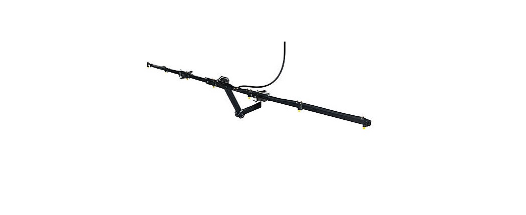
WORKHORSE BK007HM 5 or 7 Nozzle Hitch Mount Boom Instruction Manual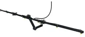
GENERAL INFORMATION
The purpose of this manual is to assist you in assembling, operating and maintaining your Hitch Mount Boom Kit Please read it carefully as it furnishes information which will help you achieve years of dependable trouble-free operation.
WARRANTY / PARTS / SERVICE
Workhorse products are warranted for one year from the date of purchase against manufacture or workmanship defects for personal or homeowner usage with proof of purchase. Workhorse products are warranted for 90 days for commercial users. Any unauthorized modification of a Workhorse brand sprayer will void warranty.
Your authorized dealer is the best source of replacement parts and service. To obtain prompt, efficient service, always remember to give the following information: 1) Correct part description and part number. 2) Model number and serial number of your sprayer.
Part description and part numbers can be obtained from the illustrated parts list section of this manual.
Whenever you need parts or repair service, contact your distributor / dealer first. For warranty work always take your original sales slip, or other evidence of purchase date, to your distributor / dealer.
ASSEMBLY INSTRUCTIONS
Tools required:
- Phillips Screwdriver
- 1/2” End Wrenches
- 9/16” End Wrenches
OPERATION
(Recommended to be used with a LG25DSS or similar 2.0 GPM or greater spot sprayer.)
Refer to your original spot sprayer operating instructions
Pressure may be regulated by opening or closing the valve located on the top of your tank. Refer to your original instructions, or see some common “Valve Operations” illustrated in this manual.
Regularly inspect the suction supply screen on the inside of the tank. Flush with water to clear any accumulated debris.
CALIBRATION
Chemical product labels may show application rates in gallons per acre, gallons per 1000 square feet, or gallons per 100 square feet. The tip chart for your sprayer shows all three rates for your convenience.
After determining how much mixed solution you are going to spray for your job, select the spraying pressure (PSI) and spraying speed (MPH) needed.
Current weather and terrain conditions must be considered when setting up the sprayer. Do not spray on windy days (over 11 MPH), and protective clothing must be worn with some products.
Be sure to read the chemical label carefully
To determine the ground speed of your sprayer, measure and mark driving distances of 100, 200, or 300 feet. Our speed chart indicates the number of seconds needed to travel these distances. Set your throttle, and with a rolling start, drive the measured distance of your choice. Adjust your throttle until you can match the number of driving seconds needed. Mark the throttle setting and note the gear range so you can use them while spraying
Add water and chemicals in the proper amounts in the spray tank and drive to your starting point. When you are ready to spray, turn your boom control valve to the “ON” position. Once the pump is turned on, the unit will begin spraying. The system pressure will decrease slightly when you see solution flowing from the spray nozzles. This is normal, the pressure will return as before when you turn the control valve to the “OFF” position.
You will find optimal spraying in the 20 to 30 PSI range.
AFTER SPRAYING
After use, fill the sprayer part way with water. Start the sprayer and allow clear water to be pumped through the plumbing system and out through the spray nozzles
Refill the tank about half full with plain water and use a chemical neutralizer such as Nutra-Sol® or equivalent and repeat cleaning instructions. Flush the entire sprayer with the neutralizing agent. Follow the chemical manufacturer’s disposal instructions of all wash or rinsing water.
Remove tips and screens from the boom. Wash tips thoroughly with water or cleaning solution (appropriate for chemical used). Blow out orifice, clean and dry. If orifice remains clogged clean it with a fine bristle (not wire) brush, or with a toothpick. Do not damage the orifice. Water rinse and dry tips before storing.
WINTER STORAGE
Drain all water and chemical out of sprayer, paying special attention to pump and valves. These items are especially prone to damage from chemicals and freezing weather
The sprayer should be winterized before storage by pumping a solution of RV antifreeze through the entire plumbing.Proper care and maintenance will prolong the life of the sprayer.
RATE CHART FOR 80/110-02 SPRAY TIP
| Pressure (PSI) | Capacity (GPM) | GALLONS PER ACRE BASED ON WATER – 20” SPACING | ||||||
| 1 MPH
88 FPM |
2 MPH
176 FPM |
3 MPH
264 FPM |
4 MPH
352 FPM |
5 MPH
440 FPM |
7.5 MPH 660 FPM | 10 MPH
880 FPM |
||
| 20.0 | 0.14 | 41.8 | 20.9 | 14.0 | 10.5 | 8.4 | 5.6 | 4.2 |
| 30.0 | 0.17 | 51.2 | 25.6 | 17.2 | 12.9 | 10.3 | 6.9 | 5.1 |
| 40.0 | 0.20 | 59.2 | 29.6 | 19.8 | 14.9 | 11.9 | 7.9 | 5.9 |
| 50.0 | 0.23 | 66.4 | 33.2 | 22.2 | 16.6 | 13.3 | 8.8 | 6.6 |
| Pressure (PSI) | Capacity (GPM) | GALLONS PER 1000 SQ. FT.BASED ON WATER – 20” SPACING | ||||||
| 20.0 | 0.14 | .96 | .48 | .32 | .24 | .19 | .13 | .10 |
| 30.0 | 0.17 | 1.18 | .59 | .39 | .30 | .24 | .16 | .12 |
| 40.0 | 0.20 | 1.36 | .68 | .45 | .34 | .27 | .18 | .14 |
| 50.0 | 0.23 | 1.52 | .76 | .51 | .38 | .31 | .20 | .15 |
| Pressure (PSI) | Capacity (GPM) | GALLONS PER 100 SQ. FT. BASED ON WATER – 20” SPACING | ||||||
| 20.0 | 0.14 | .096 | .048 | .032 | .024 | .019 | .012 | .009 |
| 30.0 | 0.17 | .117 | .059 | .039 | .029 | .024 | .015 | .011 |
| 40.0 | 0.20 | .135 | .066 | .045 | .034 | .027 | .018 | .013 |
| 50.0 | 0.23 | .152 | .076 | .050 | .038 | .030 | .020 | .015 |
Assembly Instructions
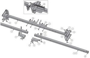
- Install Boom Arm Brackets to Boom End Sections using 5/16 x 2.75″ Hex Bolts, 5/16 x 2″ Pan Head Screws, and 5/16 HexNuts. Note the orientation and position of these parts as it is essential for proper assembly.
- Install (2) Boom Center Brackets to each end of the 45″ Center Boom Section using 5/16 x 2″ Pan Head Screws as shown.
- -Install the Boom Hinge Bolts ( 5/16 x 2″ Pan Head Screws) Throught the Boom Center Brackets and the Boom End Brackets as shown in the close up detailed view. Secure in place with the 5/16 Lock Nuts. Making sure not to overtighten bolts so boom can rotate freely.
- Install the Boom Springs over the (2) 5/16 x 2.75 Hex bolts as shown in the close up detailed view.
- Install the 5/16 Lock Nuts onto 2.75″ Hex Bolts to secure the Boom Springs in place. As shown in close up detailed view.
- Install (2) Boom Adapter Brackets to 45″ Center Boom Section as illustrated with 5/16 x 2″ hex bolts and nuts.
- Install now completed boom assembly to Hitch Mount brackets in desired location.
| PARTS LIST | |||
| ITEM | QTY | PART NUMBER | DESCRIPTION |
| 1 | 12 | 600172 | 5/16-18 Hex Flange Nut |
| 2 | 6 | 620106 | 5/16-18 UNC Lock Nut |
| 3 | 2 | 640412* | 5 Nozzle End Section (23″) |
| 4 | 2 | 640413* | 7 Nozzle End Section (38″) |
| 5 | 1 | 640414 | 45″ Center Boom Section Rev 1 |
| 6 | 4 | 640416 | Boom Center Bracket |
| 7 | 2 | 640417 | Boom Arm Bracket |
| 8 | 4 | 640423 | 5/16-18 x 2 3/4 Hex Bolt |
| 9 | 6 | 640426 | 5/16-18 x 2 UNC Pan Head Screw |
| 10 | 2 | 640428 | Boom Spring |
| 11 | 2 | 640459 | Round Sapcers 1 1/16″ Long |
| 12 | 2 | 640467 | Boom Adapter Bracket |
| 13 | 4 | 640473 | 5/16-18 x 2 Hex Cap Screw |
| 14 | 2 | 640486 | 1 1/4″ Square Cap |
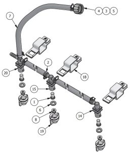
- Install Boom Clamps onto the Spray Boom Assembly. Note: Boom Clamps should be space ~20″ apart.
- Install Nozzle Body Fittings in Boom Clamps.
- Insert Check Valves into Nozzle Body Fittings.
- Insert Spray Tip into Bonnet Caps then install rubber washer and install onto Nozzle Body fittings.
- Install Hose Assembly onto valve on the Pump Manifold.

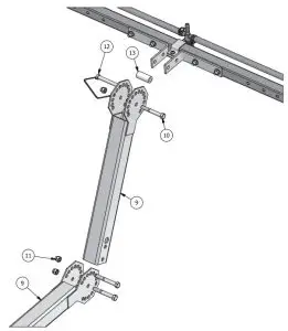
Assemble Hitch Mount Members to boom as illustrated. The Hitch Mounts can be assembled in any orientation to all various boom heights and angles. The hitch mount will fit in any standard 2″ vehicle hitch and is retained with a standard 5/8 hitch pin (not included)
| ITEM | QTY | PART # | DESCRIPTION |
| 1 | 5-7* | 600117 | Check Valve / Strainer |
| 2 | 10-14* | 600120 | 5/8″ Hose Clamp |
| 3 | 1 | 600124 | W 406 |
| 4 | 1 | 600139 | B 3400 P |
| 5 | 1 | 600140 | C3800 P Fitting |
| 6 | 7 | 600276 | Rubber Washer |
| 7 | 1 | 600302 | 3/8″ x 60″ Hose |
| 8 | 5-7* | 640432 | Spray Tip |
| 9 | 2 | 640466 | Hitch Mount |
| 10 | 3 | 640468 | 3/8-16 x 2 3/4″ UNC Hex Bolt |
| 11 | 3 | 640469 | 3/8-16 UNC Lock Nut |
| 12 | 1 | 640470 | 3/8″ Retainer Pin w/ Bail |
| 13 | 1 | 640471 | Round Spacer 1 5/8″ Long |
| 14 | 2 | 640491 | Nozzle Body Elbow Quick Outlet |
| 15 | 2-4* | 640492 | Nozzle Body TEE Quick Outlet |
| 16 | 1 | 640494* | Hose Assy. 7 Nozzle |
| 17 | 1 | 640495* | Hose Assy. 5 Nozzle |
| 18 | 5-7* | 640496 | Quick Clamp 1 1/4″ Square |
| 19 | 5-7* | 640497 | Bonnet Cap 10mm Across Flats |
| 20 | 1 | 640498 | Nozzle Body Cross 3/8 w/ Quick Outlet |
PRECISION SPRAY EQUIPMENT®, a divison of Green Leaf, Inc. 9490 N BALDWIN ST FONTANET, IN 47851 www.grnleafinc.com800-654-9808
References
[xyz-ips snippet=”download-snippet”]