WORKHORSE LG15ESS 15 & 25 GALLON SPOT
SPRAYER Instruction Manual
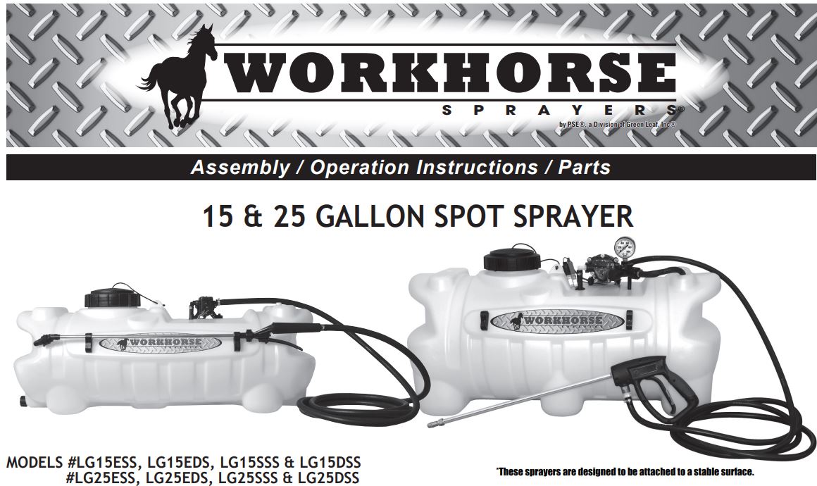
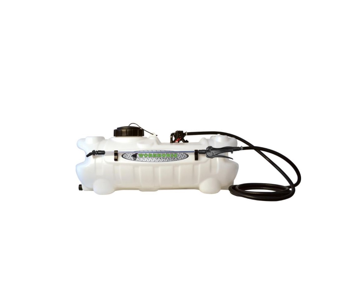
15 GALLON SPOT SPRAYER
- Polyethylene Tank
- 12 Volt Diaphragm Pump
- 1.0 GPM or 2.2 GPM
- Lever Handgun
- 15 Ft. of 3/8″ Hose (Handgun)
— GENERAL INFORMATION
The purpose of this manual is to assist you in assembling, operating and maintaining your lawn and garden sprayer. Please read it carefully as it furnishes information which will help you achieve years of dependable trouble-free operation.
— WARRANTY / PARTS / SERVICE
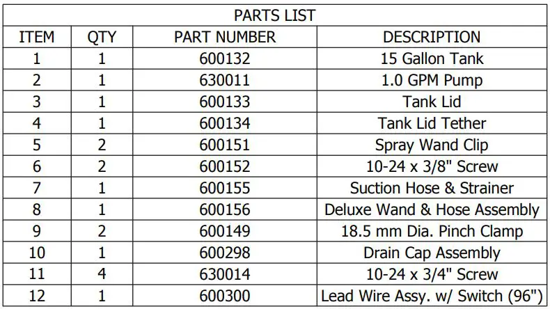
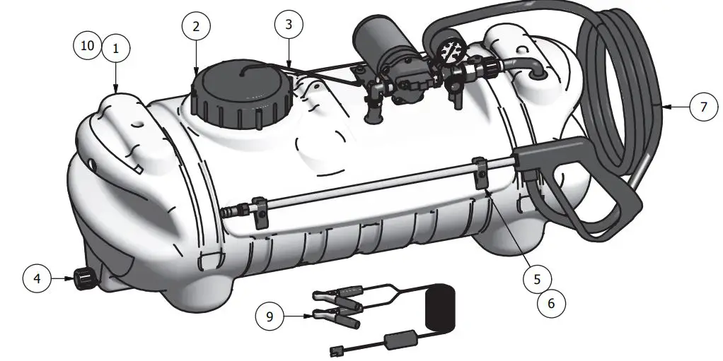
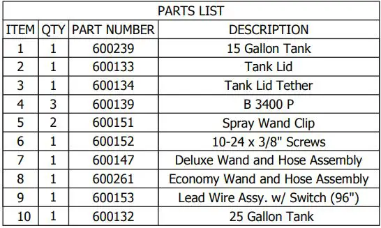
Workhorse products are warranted for one year from the date of purchase against manufacture or workmanship defects for personal or homeowner usage with proof of purchase. Workhorse products are warranted for 90 days for commercial users. Any unauthorized modification of a Workhorse brand sprayer will void warranty.Your authorized dealer is the best source of replacement parts and service. To obtain prompt, efficient service, always remember to give the following information:1) Correct part description and part number.2) Model number of your sprayer.Part description and part numbers can be obtained from the illustrated parts list section of this manual.Whenever you need parts or repair service, contact your distributor / dealer first. For warranty work always take your original sales slip, or other evidence of purchase date, to your distributor / dealer.
— OPERATION
The pumping system draws solution from the tank, through the strainer and to the pump. The pump forces the solution under pressure to the spray wand.The pump has a pressure switch which will shut the pump off when it reaches 40 PSI.Regularly inspect the suction supply screen on the inside of the tank. Flush with water to clear any accumulated debris.
— AFTER SPRAYING
After use, fill the sprayer part way with water. Start the sprayer and allow clear water to be pumped through the plumbing system and out through the spray wand.Refill the tank about half full with plain water and use a chemical neutralizer such as Nutra-Sol® or equivalent and repeat cleaning instructions. Flush the entire sprayer with the neutralizing agent. Follow the chemical manufacturer’s disposal instructions of all wash or rinsing water.
— WINTER STORAGE
Drain all water and chemical out of sprayer, paying special attention to pump and valves. These items are especially prone to damage from chemicals and freezing weather.The sprayer should be winterized before storage by pumping a solution of RV antifreeze through the entire plumbing. Proper care and maintenance will prolong the life of the sprayer.
WARNING: Some chemicals will damage the pump valves if allowed to soak untreated for a long period of time. Always flush the pump with water after use. Do not allow chemicals to sit in pump for extended times of idleness. Follow chemical manufacturers instructions on disposal of all waste water from the sprayer.WARNING:This product can expose you to chemicals including DEHP, known to the State of California to cause birth defects or other reproductive harm.
— LG15ESS & LG25ESS

Assembly Instructions1.0 — Insert Lead wire assembly into plug at rear of the pump2.0 — Join red wire of lead wire to a +12V source, the black wire should be connected to ground or the negative battery post.

— LG15EDS & LG25EDS

Assembly Instructions1.0 — Insert Lead wire assembly into plug at rear of the pump2.0 — Join red wire of lead wire to a +12V source, the black wire should be connected to ground or the negative battery post.
— LG15DSS & LG25DSS
Assembly Instructions1.0 — Install gauge in fitting as illustrated using a good thread sealant (do not over tighten)2.0 — Insert Lead wire assembly into plug at rear of the pump3.0 — Join red wire of lead wire to a +12V source, the black wire should be connected to ground or the negative battery post.
— LG15SSS & LG25SSS

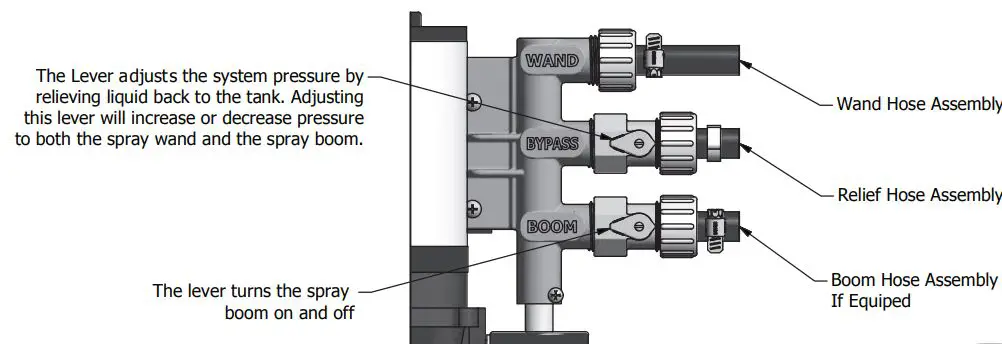
— LG15SSS, LG15DSS, LG25SSS & LG25DSS PUMP ASSEMBLY & CONFIGURATIO
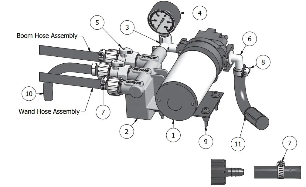
Install Wand Hose Assembly onto Swivel Barb Assembly, by placing a Hose Clamp over the open end of the hose on the Wand Hose Assembly. Then pressing the open end of the hose onto the Swivel Barb Assembly like shown. Secure in place by tightening the Hose Clamp as shown.
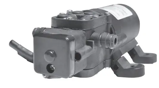
Power FLO™ 2200 Series
Specifications
MotorType: 12 VDC, permanent magnet, thermally protected, splash proof Leads: 2200-2 Model: 18 AWG, 4.5″ longDuty Cycle: Intermittent
PumpType: 2-chamber positive displacement, self priming,capable of being run dryLiquid Temperature: 110°F (43°C) Max.Priming Capabilities: 4 feet (1.2 m) suction liftMax Pressure: 40 PSI (2.8 bar)Pressure Demand Switch:Shut-Off: 40 ±5 PSI (2.8 ±0.3 bar) factory settingTurn-On: 25 ±5 PSI (1.7 ±0.3 bar) factory settingInlet/Outlet Ports: 3/8” hose barb
Dimensions Inches (mm)

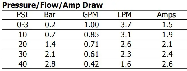
Performance
Materials of ConstructionMotor Housing: Nylon 6/6Pump Housing: PolypropyleneValves: VitonDiaphragm: SantoriniFasteners: Stainless steel and zinc plated
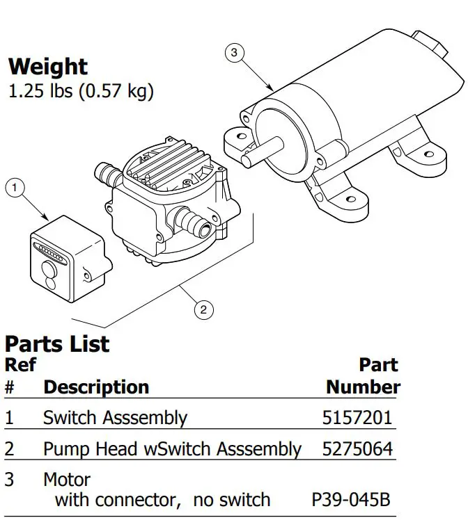
Weight1.25 lbs. (0.57 kg)
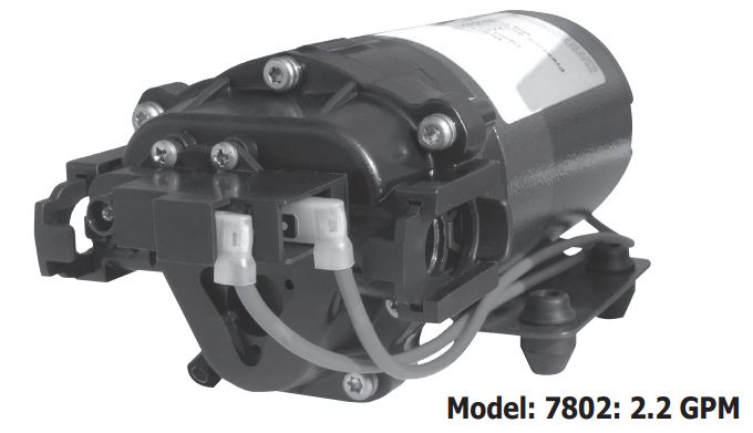
Power FLO™ 7800 Series
12 Volt DC Motor-Driven Diaphragm Pumps
Specifications
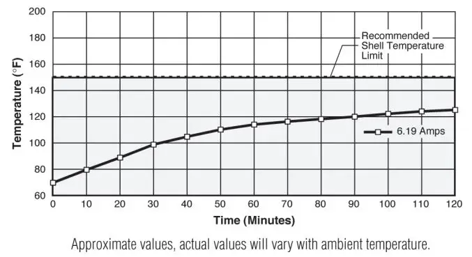
Motor:Type: 12 VDC, permanent magnet, totally enclosed, non-ventilatedLeads: 16 AWG, 12″ longDuty Cycle: See Heat Rise graphTemperature Limits: Motor is not equipped with thermal protection. For user safety, optimal performance, and maximum motor life, the motor surface temperature should not exceed 150°F (66°C) (see Heat Rise graph above right).
Pump:Type: 3 chamber positive displacement diaphragm pump, selfpriming, capable of being run dry, demand or bypass model.Certifications: NSF Standard 58Liquid Temperature: 140°F (60°C) Max.Priming Capabilities: 14 feet (4 m)Max Pressure: 60 PSIInlet/Outlet Ports: 7802: Quick Attach
Materials of Construction:Housing: Polypropylene Diaphragm: SantoriniValves: VitonFasteners: Stainless steelWeight: 6 lbs. (2.7 kg)
Installation and Operation Precautions
- The pump is equipped with a pressure sensing demand switch that controls the maximum operating pressure.
- In addition, never subject the pump to pressures above 125 PSI (8.5 bars).
- As long as there is inlet water pressure, the pump will not stop forward flow of water even if the motor is turned off. Be sure the system has positive means of shutting off water supply.
- Do not operate pump in an explosive environment. Arcing from the motor brushes, switch or excessive heat from an improperly cycled motor may cause an explosion.
- Do not locate the pump motor near low temperature plastics or combustible material. The surface temperature of the motor may exceed 250°F (120°C).
- Do not pump gasoline or other flammable liquids. Pump head materials are designed for use with water only. Do not use with petroleum products.
- Do not assume fluid compatibility. If the fluid is improperly matched to the pumps’ elastomers, a leak may occur.
- To prevent electrical shock, disconnect power before initiating any work. In the case of pump failure, the motor housing and/or pump fluid may carry high voltage to components normally considered safe. Therefore, always consider electrical shock hazard when working with and handling electrical equipment. If uncertain, consult an electrician. Electrical wiring should only be done by a qualified electrician per local and state electrical codes.
Heat Rise
Pressure Sensing Demand Switch
The Power FLO Series 7800 pump is controlled by a built-in pressure sensing demand switch. When a faucet or valve is opened down stream of the pump, line pressure drops thus starting the pump automatically. Conversely, when the valve shuts, the line pressure increases turning the pump off automatically. The pressure switch actuates in response to the pump outlet pressure at a predetermined and preset pressure. The pump label indicates the predetermined ON and OFF pressures. Typically, the OFF pressure is accurately set at the Factory and the ON pressure is within an allowable range below that value. In response to the characteristics of the system in which the pump is installed, the flexibility and length of the tubing, the faucet or valves and the duration that they are open; these pressure settings may vary. Therefore, variation in pressure setting is expected with use and over time.
Adjusting the Pressure Switch:Should the pressure switch OFF setting vary with use and time to an unsuitable value, it may be adjusted for optimum performance. Turn the setscrew clockwise to increase the OFF pressure setting and counter clockwise to decrease. The screw should not be adjusted more than one half turn without consulting the Factory. Excessive adjustment of the pressure switch could cause low system pressure, rapid cycling ON/OFF operation, and reduced pump and motor life. Damage may occur. The Warranty does not cover improper adjustment of the pressure switch.
Servicing
Every Year: Check system against operating standards.Every 2-3 Years: We recommend replacing the diaphragm and checking against operating standards.
* Important return safety instructions:When you return your pump for warranty or repair, you must always do the following:
- Flush chemical residue from the pump (best done in the field).
- Tag pump with type of chemicals having been sprayed.
- Include complete description of operation problem, such as how pump was used, symptoms of malfunction, etc. Since pumps can contain residues of toxic chemicals these steps are necessary to protect all the people who handle return shipments, and to help pinpoint the reason for the breakdown.
Troubleshooting Guide
Problem/Causes and Remedies:
Pump will not StartCheck:
- Correct voltage (±10%) and electrical connections
- Fuse or breaker
- Pressure switch operation and correct voltage at switch
- Rectifier or motor for open or grounded circuit
- Locked drive assembly
Pump will not Prime (No discharge with motor running)Check:
- Debris in strainer
- Restriction (kinks) in inlet/outlet tubes
- Debris or swelling in inlet/outlet valves
Pump will not Shut Off (Output line closed and no leaks)Check:
- Air trapped in outlet line or pump head
- Correct voltage to pump
- Debris in pump inlet/outlet valves
- Loose drive assembly or pump head screws
- Pressure switch operations/adjustments
Leaks from Pump Head or SwitchCheck:
- Loose screws at switch or pump head
- Switch diaphragm ruptured or pinched
- Punctured diaphragm if fluid is present
Spray & Pump FAQs
–Why does the pump not run all the time?This is a demand pump and only runs with flow; spray wand, by-pass, spray tips or leak in system–Why does the pump surge while using the spray wand?Low flow may cause the pump to surge (or cycle). This could happen when the spray wand is adjusted for a small or fine spray pattern. To overcome, slightly open the by-pass valve.–How do I adjust the pressure?Pressure should be adjusted by regulating the by-pass valve (slightly opening or closing).–What is the optimal operating pressure?40 PSI – This can be accomplished by turning on the pump and adjusting the bypass valve until the gauge reads 40 PSI (or slightly higher). The pump will run continuously. Ensure that the boom and/or handgun is not spraying while you set the pressure. The pressure will drop slightly when the boom and/or handgun is operated.–What pressure should the pressure gauge read?Please refer to the operation instructions for boom operating pressures, varying boom pressures can be achieved by regulating or adjusting the by-pass valve. Typically the spray wand will be operated between 20 and 40 PSI.–My pump quit and will not restart – what should I check?Check all electrical connections. Ensure switch is in the on position. Check in-line fuse and/or fuse in car adapter end. Ensure correct voltage +/- 10%. 12-13 volt–Low flow or no flow at all – what should I check?Check for a clogged suction hose and/or suction strainer. Often you will need to clean the suction strainer. Check for proper voltage.–Is there a fuse for the sprayer?Yes, either an in-line fuse, a fuse located in the car adapter housing or both.–What size fuse should I use as a replacement?7.5 amp–What is the range of the spray wand?35 feet max–How should I clean the tank after use?Tank should be cleaned with a tank cleaning agent, and then rinsed with water.–Is there an adjustment screw on the pump to adjust pressure?Yes, please refer to the operation instructions, “Adjusting the Pressure Switch”.–How do I remove / replace fuse?Unscrew in-line fuse connector, or unscrew the car adapter housing.–Can the spray tip on the wand be replaced with a different type of tip? Yes, however your wand comes with a #18 tip which is standard. Brass tips generally produce better spray patterns than plastic.–Each time I turn on the pump my fuse blows.1) Excessive voltage 2) Improper adjustment of the pressure switch 3) Damaged wiring harness.–What is the warranty (time duration) on pump, tank, and accessories?2 years as stated in operation instructions.–Pressure gauge reads 85 -90 psi before shutting off – should pump shut off at 60 psi?Pump 7802 2.2 GPM comes preset from the factory to shut off at 60 PSI. Should this vary please see, “Adjusting the Pressure Switch” in the operation manual. Turn on pump and hold spray wand open, slowing adjust until the pump shuts off at 60 PSI.–Pump continues to run and surge when not spraying.Ensure the by-pass is completely closed and your system has no leaks. Check by-pass hose to ensure no fluid is passing through the valve while in the closed position. If so replace valve.
WARNING – Ensure the wiring harness does not become pinched or damaged in any way. This may damage the pump or cause the wiring harness to overheat, resulting in a melt down or fire.
PRECISION SPRAY EQUIPMENT®, a division of Green Leaf, Inc. 9490 N BALDWIN ST FONTANET, IN 47851 www.workhorsesprayers.com888-433-663
![]()
References
[xyz-ips snippet=”download-snippet”]