![]() 4K AV over IP JPEG 2000 Encoder and DecoderNHD-400-E-TX | NHD-400-E-RXQuickstart Guide
4K AV over IP JPEG 2000 Encoder and DecoderNHD-400-E-TX | NHD-400-E-RXQuickstart Guide
![]() WyreStorm recommends reading through this document in its entirety to become familiar with the product’s features prior to starting the installation process.
WyreStorm recommends reading through this document in its entirety to become familiar with the product’s features prior to starting the installation process.
![]()
![]() IMPORTANT! Installation Requirements
IMPORTANT! Installation Requirements
- Visit the NetworkHD product pages download section at wyrestorm.com to check for the latest firmware, document versions, and WyreStorm Management Suite configuration tools.
- Install the latest firmware onto all encoders and decoders using the Maintenance Tool found in the Management Suite and via the NHD-000CTL web interface.Full firmware update instructions are included with the firmware download.
- NetworkHD requires a Layer 2+ or Layer 3 managed switch network with support for Multicast & IGMP snooping enabled.
- WyreStorm highly recommends using network switches listed in the NetworkHD Switch Recommendation Guide. These switches have been verified by WyreStorm to meet the requirements of a networked system.
- Configure all network switches to the exact specification of the guides at wyrestorm.com prior to connecting any NetworkHD devices.
- NetworkHD uses stateless address autoconfiguration (auto-IP) to assign link-local IP addresses in the range of 169.254.x.x to encoders and decoders out of the box. Your PC must be set to an address in this range in order to discover the encoders, decoders, and NHD-000-CTL.
- WyreStorm recommends the use of the NHD-000-RACK4 for installations containing multiple NetworkHD devices. Use this product provides an enclosure to mount and secure all NetworkHD devices in a standard 19inch rack frame (EIA-310).
In the Box
1x NHD-400-E-TX or NHD-400-E-RX1x 4-pin Terminal Block (RX only)2x Mounting Brackets for NHD-000-RACK42x Wall Mounting Brackets1x Quickstart Guide (This Document)
Additional Information
More information and required software can be found within the Download section of the product page on wyrestorm.com.
- Management Suite v1.6 or Higher
- NetworkHD Switch Recommendations
- NetworkHD Switch Mapping Worksheet
- NetworkHD Switch Configuration Guides
- NetworkHD Touch Installation Guide
- NetworkHD Touch User Guide
- Drivers for Popular Control Systems
Basic Wiring Diagram
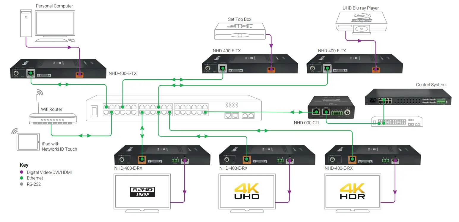
Wiring and ConnectionsWyreStorm recommends that all wiring for the installation is run and terminated prior to making connections to the switcher. Read through this section in its entirety before running or terminating the wires to ensure proper operation and to avoid damaging equipment.
![]() IMPORTANT! Wiring Guidelines
IMPORTANT! Wiring Guidelines
- The use of patch panels, wall plates, cable extenders, kinks in cables, and electrical or environmental interference will have an adverse effect on the signal transmission which may limit performance. Steps should be taken to minimize or remove these factors completely during installation for best results.
- WyreStorm recommends using pre-terminated HDMI and DP cables due to the complexity of these connector types. Using pre-terminated cables will ensure that these connections are accurate and will not interfere with the performance of the product.
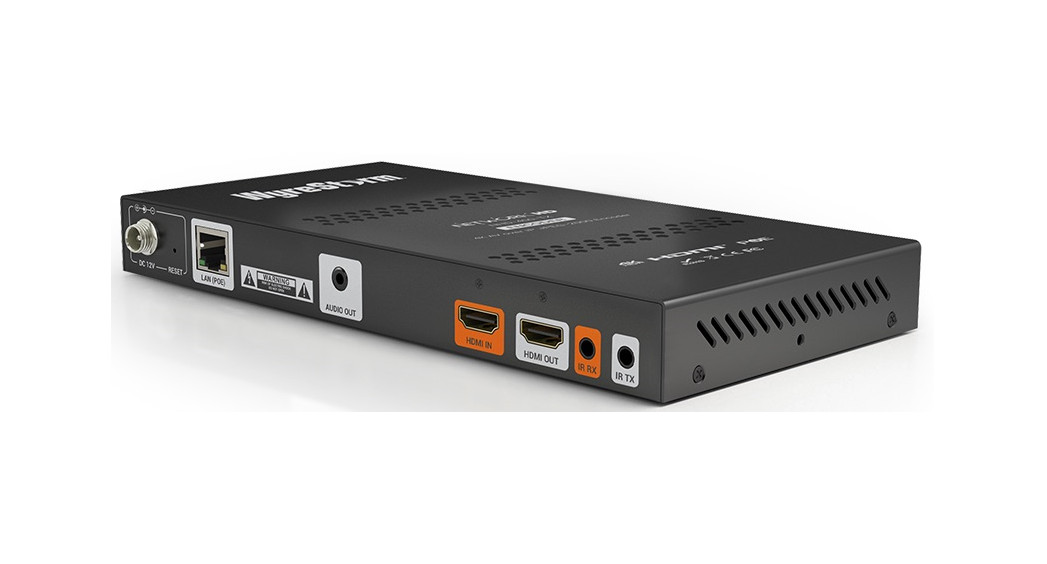
LAN Port WiringThe NetworkHD 400 Series LAN port is a 1GbE link for connection to a 1000BASE-T Ethernet device port. Refer to IEEE 802.3ab for official guidance on the Ethernet link. Cables must be tested to 100MHz across the entire link. 1000BASE-T uses the IEC 60603-7 8P8C modular connector.
RS-232 Wiring
The NetworkHD 400 Series uses 3 pins from a 4 pin phoenix connector. The RS-232 communication does not utilize hardware flow control. Please ensure that the data flow direction is observed (i.e. the NetworkHD RS-232 TX pin is connected to the attached device’s RX pin) – pinouts on 3rd-party equipment will vary – please check the relevant device documentation.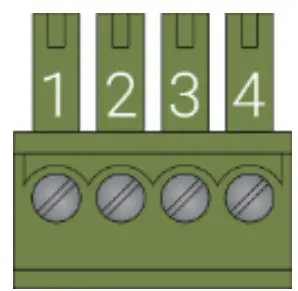
| WyreStorm Connector | 3rd Party Device | ||
| Pin 1 | 12V DC Out | No Connection | Reserved |
| Pin 2 | TX (Transmit) | —> To —> | RX (Receive) |
| Pin 3 | RX (Receive) | —> To —> | TX (Transmit) |
| Pin 4 | G (Ground) | —> To —> | G (Ground) |
Setup and Configuration
![]() IMPORTANT! Installation Guidelines
IMPORTANT! Installation Guidelines
- Do not connect the power supply until all NetworkHD devices are connected to the network switch.
- NetworkHD 400 Series uses either DHCP (where a DHCP server is reachable) or stateless address autoconfiguration (auto-IP) to assign link-local IP addresses in the range of 169.254.x.x to encoders and decoders out of the box. Your PC must be set to an address in this range in order to discover the encoders, decoders and NHD-000- CTL.
- In order to configure the NetworkHD encoders and decoders, the “AV” port on the NHD-000-CTL MUST be connected to the same LAN/VLAN and Subnet as the NHD encoders and decoders.
- In order for the devices in the system to be controlled via a 3rd party controller on a different VLAN, either the “CONTROL” port on the NHD-000-CTL can be connected to the other LAN/VLAN and Subnet containing the control system directly (isolated approach, recommended) or the use of a router must be employed to route the data between different subnets by using the NHD-000-CTL “AV” port only.
- The NHD-000-CTL’s two Ethernet interface ports are designed to reside in different Subnets and cannot have IP addresses/subnet masks that cause an “overlap” of the Subnets assigned to them. When using a single Network or VLAN, for example when using NetworkHD Touch – do not connect both ports only use the “AV” port of the NHD-000-CTL.
Installation and Connections
- Install NHD devices to allow airflow through the product – when rack mounting, WyreStorm recommends using the NHD-000-RACK4 kit. The install location should be dry, well ventilated, and guaranteed to maintain the mandatory operating temperature range of the product.
- Connect sources to the NetworkHD encoders using an HDMI cable from a quality brand such as WyreStorm Essentials ensuring a firm port connection.
- Connect the HDMI display to the NetworkHD decoders using an HDMI cable from a quality brand such as WyreStorm Essentials ensuring a firm port connection.
- Connect NetworkHD encoders, decoders, and CTL to the network switch using well terminated and tested category cable, whilst ensuring compliance with IEEE 802.3ab (for CTL, encoder, and decoder 1GbE ports).
- Optionally connect the decoder’s RS-232 port to equipment following the RS-232 pinout section in the appropriate Quickstart Guide.
![]() Download the NetworkHD Switch Mapping Worksheet from any NetworkHD product page to keep track of MAC addresses, device, and alias names for later reference. This will aid the setup process in NetworkHD Console and help with any reconfiguration or troubleshooting.
Download the NetworkHD Switch Mapping Worksheet from any NetworkHD product page to keep track of MAC addresses, device, and alias names for later reference. This will aid the setup process in NetworkHD Console and help with any reconfiguration or troubleshooting.
NetworkHD Console Configuration
In addition to the steps below, more information on configuration can be found in the NetworkHD Installation Guide.
- Ensure that a correctly configured network switch has been set up in Guides is available from the WyreStorm website.
- Connect a computer running WindowsTM to the same LAN/VLAN as the NetworkHD components and ensure its IP is within the same subnet as the NetworkHD default 169.254.x.x IP addresses. Ensure that no DHCP server will allocate addresses. The NHD-000-CTL “AV” port is set to a static address of 254.1.1 by default — do not choose this address for your PC.
- Power On the NHD-000-CTL by connecting to a PoE switch or by using the included DC power adapter.
- Power On the NHD devices by connecting the device to a PoE switch or by using the optional power adapter, PSU-12V-1A, available separately.
- Once all devices have booted, open the WyreStorm Management Suite (Available from the WyreStorm website) and launch the NetworkHD Console software, and press search.Note: If no devices are discovered, verify that encoders/decoders, CTL, and PC are within the same subnet scope and within the same range of the CTLs “AV” Port and disable or create an exception for the NetworkHD Console in Windows Firewall or any 3rd-party firewall/malware/antivirus software.
- Configure the system as per the instructions in the NetworkHD Installation Guide. Right, Click on the 400 Series device to see its available options, including setting the device’s IP address and setting an Alias name. You will also find other configuration options under the Batch SettingsNote: If a 3rd Party control system with a WyreStorm driver for NetworkHD is going to be used, the encoders must use the Alias prefix IN1, IN2, etc. This also applies to decoders, OUT1, OUT2, etc. For example, IN1-Satellite Receiver 1
- Upload the configuration to the NHD-000-CTL by right-clicking the CTL in the Other Devices section and selecting Upload.
- Configure the scaling and HDCP values of each decoder based on the requirements of the content and display using the settings found in the Video tab in the Batch Settings
Troubleshooting
![]() Verify that all NHD devices contain the latest version of the firmware. This will ensure that all devices are up to date and working at their highest performance level.
Verify that all NHD devices contain the latest version of the firmware. This will ensure that all devices are up to date and working at their highest performance level.
NetworkHD Software fails to locate TX/RX/CTL Devices
- Verify that all NHD and Network devices are powered On.
- Adjust Windows Firewall Settings – Create an exception for NetworkHD Console.
- Verify that the PC, CTL “AV” Port, and NHD encoders and decoders are on the same LAN/VLAN/Subnet.
- Verify that all network switches share the same VLAN configuration.
- Reboot all system components including the NHD-000-CTL and the PC.
- Ensure that only one CTL port is connected per LAN/VLAN. If only one LAN/VLAN exists only use the “AV” port.
- Ensure the network switch is fully configured per the appropriate switch configuration guide.
Failure to Connect to CTL Controller
- Follow the previous steps for failing to connect to devices. If these are unsuccessful, press and hold the reset button on the front of the CTL for 5 seconds.
- After a reboot, the CTL will be returned to the default IP address of 192.168.11.243 for the control port and 169.254.1.1 for the AV port.
No Image Appearing on Displays
- Verify that all NHD, Network, Source, and Display devices are powered On.
- Verify that the configuration in NetworkHD Console is correct based on the system layout and components used.
- Ensure the network switch is fully configured per the appropriate switch configuration guide.
- Test sources and displays by connecting them directly together.
- Swap out the HDMI cable.
Warranty Information
WyreStorm Technologies LLC warrants that its products to be free from defects in material and workmanship under normal use for a period of five (5) years from the date of purchase. Refer to the Product Warranty page on wyrestorm.com for more details on our limited product warranty.
![]()
Specifications
| Connectivity | ||
| 1 Encoder (TX) | Decoder (RX) | |
| Inputs | lx HDMI IN: 19-pin HDMI TypeA | lx LAN (POE): 8P8C`RJ45″ Socket ANSI/TIA-568 |
| Outputs | lx LAN(PoE): 8P8C “RJ45” Socket ANSI/TIA-568 | lx HDMI OUT: 19-pin HDMI Type A lx RS-232: 4-Pin Phoenix |
| Transmission | ||
| Transmission Encoding | Proprietary stream encoding. Video compression based on JPEG 2000 | |
| End to End Latency | With RX, 1 video frame (Passthrough mode) 2 video frames (scaling/video wall) e.g. 16ms @ 60Hz | |
| Max Transmission Bit Rate | 850Mb/s | |
| Video | ||
| HDMI | 300MHz Max.TMDS Clock | |
| Maximum Data Rate | 8.91Gb/s HDMI | |
| Video Resolutions (Max) | 1280x720p @50/59.94/60Hz 12bit 4:4:4/RGB1920x1080i @29.97/30Hz 12bit 4:4:4/RGB1920x1080p @23.98/24/25/29.97/30/50/59.94/60Hz 12bit 4:4:4/RGB3840x2160p @23.98/24/25/29.97/30Hz 10/12bit4:2:2/4:2:0 HDR103840x2160p @23.98/24/25/29.97/30Hz 8bit 4A:4/R013 3840x2160p @50/59.94/60Hz 8bit 4:2:0720x480p @59.94/60Hz 12bit 4:4:4/RGB720x576p @50Hz 12bit 4:4:4/RGB60fps Progressive 4:4:4/RGB: 640×480 1800×600 I 1024x76811280x8001 1280×960 I 1280×1024 I 1360x/68 i 1366x76811400x105011440x9001 1600×12001 1680×1050 I1920x1200 | Passthrough mode:Output at RX matches input at TX except for:1)YUV 4:2:0 converted to 8bit RGB2)For resolutions above 1920×1200 at 50/60Hz frarnera:’ is halvedScaler mode:User-selectable scaled output1)All formats converted to 8bit RGB2)Up to 3840x2160p @30Hz |
| Supported Standards | HDR10 I BT.2020 I BT.709 I 3D Video | |
| Audio | ||
| Audio Formats | PCM up to 8ch I Bitstream audio formats including Dolby Atmos & DTS:X | |
| Communication and Control | ||
| Ethernet | IEEE 802.1ab 1000BASE-T | |
| HDCP | HDCP 2.211.x | |
| EDID | Programmable EDID I EDID Copy/Import I Custom EDID | |
| CEC | Programmable CEC Commands I Custom Command Generation (RX Only) | |
| RS-232 | Programmable RS-232 CommandslCustom Command Generation (RX Only) | |
| Installation & Mounting | ||
| Compatible Rack Mount Kit | NHD-000-RACK4 | |
| Included Accessories | Wall Mount Brackets I Brackets for NHD-000-RACK4 | |
| Orientation | Observe product chassis text | |
| Power | ||
| Power Over Ethernet | IEEE 802.3af (15.4W at PSE) | |
| External Power Supply | Optional part: PSU-12V-1A | |
| Nominal Power Consumption | 8W | |
| Environmental | ||
| Operating Temperature | 0 to + 45°C (32 to + 113 °F), 10% to 90%, non-condensing | |
| Storage Temperature | -20 to +70°C (-4 to + 158 °F), 10% to 90%, non-condensing | |
| Maximum BTU | 51.18 BTU/hr | |
| Dimensions and Weight | ||
| Rack Units/Wall Box | <1 U flat on shelf 16U in NHD-000-RACK4 | |
| Height | 25mmflin | |
| Width | 220mm/8.67in | |
| Depth | 130mm/5.12in | |
| Weight | 0.75kg/1.65Ibs | |
| Regulatory | ||
| Safety and Emission | CE I FCC I RCM ICE LVD I RoHS |
 report this ad
Note: WyreStorm reserves the right to change product specification, appearance or dimensions of this product at any time without prior notice.
Copyright © 2020 WyreStorm Technologies | wyrestorm.comNHD-400-E-TX | NHD-400-E-RX Quickstart Guide | 200107UK: +44 (0) 1793 230 343 | ROW: 844.280.WYRE (9973)[email protected]
References
[xyz-ips snippet=”download-snippet”]