![]()
4010-PRO-X 75 Watt Soldering Iron StationInstructions
PLEASE READ THESE INSTRUCTIONS BEFORE USING YOUR NEW X-TRONIC MODEL #4010-PRO-X SOLDERING STATION
PRODUCT SPECIFICATIONS
| Model | XTR-4010-PRO-X |
| Dimensions | 6.75 x 6.5 x 4.75 in / 17.1 x 16.5 x 12 cm |
| Weight | 4.0 lbs / 1.8 kg |
| Working Environment | 32°F – 104°F / 0°C – 40°C |
| Storing Environment | -4°F – 176°F / -20°C – 80°C |
| Storage Humidity | 35% – 45% |
| Temperature Range | 392°F – 932°F / 200°C – 500°C |
| Temperature Stability | ± 3.6°F / 2.0°C (Static) |
| Grounded Tip Voltage | < 1 mV |
| Tip Impedance | < 10 |
| Display Type | LED – Bright White |
| Cable Length (Material) | a 54 in 1137 cm (Silicone) |
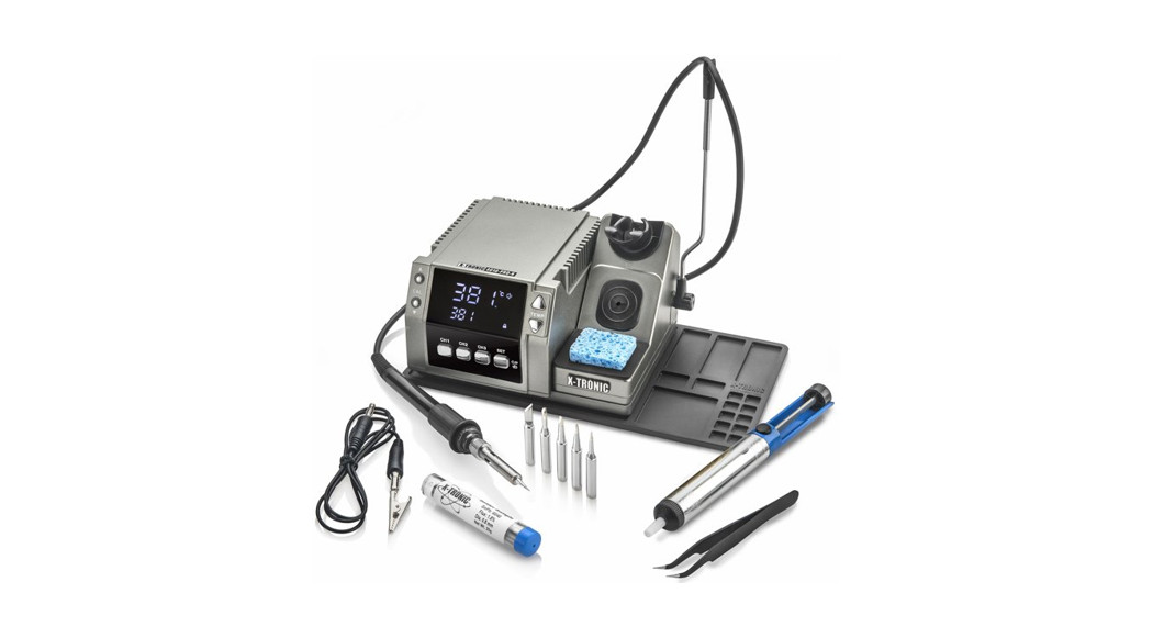
PACKAGE CONTENTS
- Main Power Unit
- 60 Watt Soldering Iron with Ergonomic Grip
- 54” Silicone Cord on Soldering Iron (Virtually NO Memory)
- Soldering Iron Holder – Attached to Main Unit
- Soldering Cord Extension Holder
- Anti-Static Grounding Wire
- Fuse Replacement (1) – (In the Fuse Holder in the Back of the Unit)
- Silicone Base Mat for Soldering Station & Holding Tools/Parts
- Brass Sponge Tip Cleaner – Inside Soldering Iron Holder
- Wet Sponge Tip Cleaner
- Power Cord
SAFETY PRECAUTIONS
- Always use a grounded outlet for the unit.
- Always turn the power off and unplug the unit when not in use.
- Never use the soldering iron near any flammable substance, material, or gas.
- Never touch the metallic components of the soldering iron while the unit is on. They are extremely hot and will cause serious burns instantly.
- Always turn the power off, unplug the unit, and let it fully cool down before attempting to replace any parts (tips, heating element, etc.)
- Use only genuine replacement parts for this unit.
- Do not use the unit for any application other than soldering.
- Do not tap the soldering iron against the workbench to remove residual solder.
- Do not modify the unit in any way.
- When replacing consumable parts, only use approved manufacturer parts.
- Do not get the unit wet or use when your hands are wet.
- The soldering process will produce smoke – ensure the area is well ventilated.
UNIT PARTS
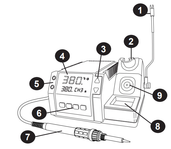
| 1. Soldering Cord Extension Holder2. Soldering Iron Holder3. Temperature Control Buttons4. Bright White LED Display5. Calibration Control Buttons | 6. Function Buttons7. Soldering Iron8. Wet Sponge Holder9. Brass Sponge Holder |
INITIAL SET-UP
- Open the package and check that all parts are present and are not damaged. If anything is missing or damaged, please contact X-Tronic immediately for assistance (see back cover for contact information).
- Remove everything from the packaging.
- Place the soldering cord extension holder in the bracket on the right-hand side (see #1 in the drawing above).
- Plug the soldering iron into the back of the unit and place the soldering iron in the soldering iron holder (see #2 in the drawing above). Secure the core in the extension holder (optional).
- The brass sponge is in the silicone opening right below the soldering iron (see #9 in the drawing above).
- Wet the blue sponge and place in the space at the base of the soldering iron holder (see #8 in the drawing above).
- Plug the 3-prong AC cord into the back of the unit and then into a grounded outlet to prevent electric shock or injury.
USER INTERFACE
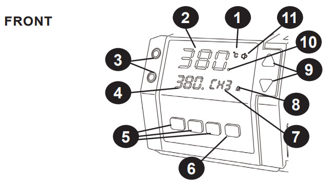
| 1. Celsius / Fahrenheit Indicator2. Actual Temperature of the Soldering Iron Heating Element3. Calibration Buttons4. Set Temperature5. 3 Preset Memory Channels6. Function Setting Button | 7. Currently Selected Preset Channel8. Lock / Unlock Indicator9. Temperature Setting Buttons10. PID (Proportional-Integral-Derivative) Self Correcting Indicator Light11. Mute Indicator |
BACK
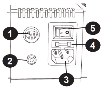
| 1. Soldering Iron Socket2. Ground Wire Socket3. Power Cord Socket | 4. Fuse5. Power Switch |
OPERATING INSTRUCTIONS
- Place the soldering iron in the holder.
- Turn the unit on with the power switch on the back of the unit.
- Set the desired temperature using the TEMP UP and DOWN buttons on the right side of the unit or by pressing one of the Preset Memory Channels. This temperature will show in the lower-left corner of the display.
- Wait for the unit to stabilize at the desired temperature. The actual temperature of the heating element/soldering tip is displayed on the top of the display. See page 6 for a detailed diagram of the display screen.
- Remove the iron from the holder and flood the tip with a good quality rosin core solder-preferably 63/37 or 60/40 grade solder.
- Wipe the tip across the moist sponge or dip the iron into the brass sponge to remove excess solder. The tip should then be shiny.
- The soldering iron is now ready to solder. Proceed according to your standard working practice.
FEATURES
CELSIUS / FAHRENHEIT CONVERSIONTo switch between displaying the temperature in Celsius or Fahrenheit, press the SET once quickly. The display will toggle between °C / °F.MUTE / UNMUTE FUNCTIONThe unit beeps when buttons are pushed or when it goes into sleep mode. To toggle between Mute and Unmute Mode, press and hold the SET button for 3 seconds. When the unit is Muted a Red speaker with a line through it will appear, when the unit is Unmuted a White speaker will appear.SET MEMORY PRESET CHANNELSTurn the unit on, set the desired temperature by pressing the TEMP UP or DOWN arrows on the right side of the unit. Wait for the unit to stabilize at the desired temperature. Then to set a Channel Preset, press and hold the channel button to be programmed for 5 seconds. The unit will beep and the channel has been set.LOCK / UNLOCK MODEThe unit can be locked once it is set so that none of the buttons on the front of the unit will engage. If the unit is turned off while in Locked Mode, it will still be locked when the unit is turned back on. The unit WILL still go into and out of Sleep Mode while it is locked.To toggle between Locked and Unlocked Modes, press and hold the CH2 & CH3 buttons simultaneously for 2 seconds. The indicator on the display will show a Red closed lock when the unit is locked and a White open lock when the unit is unlocked.CALIBRATION FUNCTIONWhen is it time to Calibrate your Soldering Station?All X-Tronic Soldering Stations come with a high-quality ceramic heating element in the soldering iron that is calibrated to within ±3.6°F/2.0°C of the temperature that is shown on the LED Display. While calibrating to the exact temperature is the ultimate goal, this heating element, and tip design is as close as can be achieved with this technology.The age of the heating element, the hours of use, and the temperature at which the soldering iron is regularly used will affect the life of the heating element and can cause fatigue. When a heating element begins to fatigue, the heat that is transferred to the soldering tip from the heating element will begin to drop. If the typical temperature used to solder is not working as well as when it was new, then it might be time to calibrate the unit.Note: Heating elements are consumable parts for soldering stations. There will come a time when the heating element stops working due to age and/or too much deterioration. At this point, it will need to be replaced and cannot be calibrated. Heating elements for this unit can be found on our website (XTronicUSA.com).Calibration InstructionsOnce the desired temperature has been set and the temperature of the unit stabilizes, measure the heat at the soldering tip using a high-quality and well-calibrated soldering tip tester. If the temperature shown on the unit’s display does not reflect the temperature shown on the tester, the unit can be calibrated by simply pushing the CAL UP or DOWN buttons on the left side of the unit to compensate for the degrees of variance.Note: This unit can be calibrated VERY EASILY, if this feature is used please be aware that without proper testing equipment and methods, the outcome could be less than desirable.
IMPORTANT – PLEASE READ
Infrared (IR) Thermometers should NOT be used to measure the temperature of the soldering tip as they often provide inaccurate readings. All IR Thermometers are different and the capability depends on the Distance to Spot (D:S) ratio of the model being used. Many IR thermometers have a D:S ratio of 8:1 or 12:1 which means that the thermometer needs to be a distance of 8” or 12” in order to read a 1” spot size. The tip of a soldering iron is approximately 2 to 3 mm (.07-.11”), requiring the thermometer tobe 0.8” or 1.2” away from the tip. However, the IR thermometer also has a minimum distance it needs to be away from the object. Most IR thermometers will not be capable of measuring such a small spot size and will provide disappointing calibration results.
SLEEP FUNCTION
If the soldering iron sits idle in the soldering iron holder for 10 minutes (default time), Sleep Mode will be activated. The screen will switch to “—” and the soldering iron will cool down to 200°C (392°F). The unit will beep (if not muted) to indicate when Sleep Mode is activated. To bring the unit out of Sleep Mode, simply pick up the soldering iron from the holder.Note: The unit will NOT go into sleep mode unless the soldering iron is in the holder.To change the default time before sleep mode is activated, turn the unit off with the switch on the back of the unit. Press and hold the CH1 button while switching the unit on. Continue holding the CH1 button for 3 seconds, the Set Temperature display (lower left corner) will change to show the number of minutes before sleep mode activates. Once this changes, release the CH1 button and use the TEMP up and down buttons to set the sleep time. The sleep timer can be set between 00-30 minutes, in 1-minute increments. Once the desired time has been set, press the CH1 button again and the setting will be saved.Note: Setting the sleep timer at “00” will turn the sleep function off and the unit will NOT go to sleep regardless of how long the unit sits idle in the soldering station holder. It is not recommended to turn the sleep timer off for normal use. The use of the sleep timer will help extend the life of the heating element and tip if the unit is left on for long periods of time.
MAINTENANCE
SOLDERING TIP CARE
- For first use, allow the tip to rise to a stable temperature. Clean the tip on the damp sponge and tin the tip (apply a small amount of fresh solder to the tip).
- The soldering iron should be run in the 330°C ~ 360°C range for regular use, which is the normal temperature range for most soldering applications. The heating element should last for 6 to 12 months depending on hours of use when the unit is regularly used within this range.
- Never hit the soldering iron or tip on anything when trying to remove excess solder.
- Do not use extreme temperatures with the soldering iron tips, doing so will shorten the life span of the tip.
- Clean the tip before each use, using the brass cleaning sponge for better temperature stability during use.
- Always clean and tin the tip after each use. This will aid in the prevention of oxidation on the tip and help extend its life span.
- Do not allow the soldering iron or the tips to sit idle at high temperatures for extended periods of time.
- Never use a file or other abrasive materials to remove oxidation from the tips.
- To remove oxidation, simply flood the tip with fresh solder and wipe it clean on the damp sponge or copper cleaning pad. This may need to be repeated several times for badly oxidized tips.
- To remove the yellowing on the tip shaft (which is perfectly normal, especially after first use) clean with 90% Isopropyl alcohol.
WARNING: Do NOT use anti-seize or any other lubricant on the tip retainer or heater of the soldering iron
INSTALL/REMOVE SOLDERING IRON TIP
- Turn off the power to the unit and unplug from the power source.
- Allow the soldering iron and tip to fully cool down and reach room temperature.
- Loosen the metal nut at the base of the metallic shaft of the soldering iron.
- Slide the metallic tube off of the soldering iron and tip.
- Slide the tip-off of the heating element.
- Repeat in the reverse order for installation. Do not over-tighten the nut on the soldering iron.
REPLACING THE HEATING ELEMENT
- Turn off the unit and unplug it from the power source.
- Allow the soldering iron to cool down to room temperature. Never attempt to remove the tip while the iron is hot.
- Unscrew the Black Bakelite Polymer Retaining Cap and slide off the full tip assembly.
- Push the Power Cord through the bottom of the soldering iron while simultaneously pulling gently on the heating element to expose the heating element.
- De-solder the 2 Thin (red or white) wires and the 2 Thick (blue) wires that have heat shielding on them from the circuit board and pull the heating element away from the board. Please take note of the location of the wire thickness/color for the installation of the new heating element (see diagram below).
- On one side of the circuit board solder a thin wire and a thick wire to 1 2 (see diagram below).
- Flip the circuit board over and solder a thin wire to 3 and a thick 4 wire to (see diagram below).
- Pull the cord back gently and align the circuit board to the slots on the iron so the cord can be pulled back to its original position.
- Replace Bakelite Polymer Retaining Cap and screw back on andhand tightens – Do NOT over-tighten.
- Install the soldering tip, slide the metal soldering tip retaining collar and hand tighten it. Plug the AC cord back into a grounded outlet.
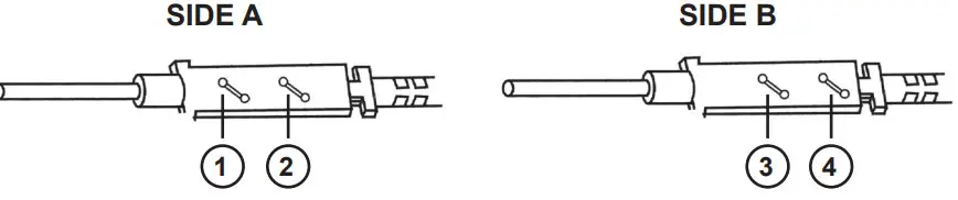
NOTE: The wires on the heating element can be soldered back onto either side of the circuit board, as there is no polarity for the element.
REPLACING THE FUSE
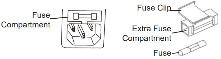
- Unplug the power cord from the outlet.
- Remove the fuse compartment by pressing a flat head screwdriver into the divot just inside the power socket under the fuse compartment.
- The fuse that is in use will be in the fuse clip, the extra fuse is below it. If the fuse is damaged, replace it with a new fuse.
- Insert the fuse compartment back into the unit.
TROUBLESHOOTING
| ISSUE | POSSIBLE SOLUTIONS |
| The unit does not have power | •Ensure the power cord is securely attached to both the unit and the outlet and that the unit is powered on at the back of the unit.•Ensure that the outlet is functional.•Ched< the fuse in the back of the unit to see if it is in good working condition. If not, replace the fuse. |
| S-E Error | •Ensure the soldering iron is securely plugged into the back of the unit.•The heating element may need to be replaced |
| The tip is not heating up as expected | •Ensure the soldering iron is securely plugged into the back of the unit.•The soldering tip could be oxidized, it is important to always tin your tip and keep it clean. See lip Maintenance section of manual.•The heating element may need to be replaced•Unit may need to be calibrated – see Calibration section of manual |
3-YEAR LIMITED WARRANTY
THIS LIMITED WARRANTY GIVES YOU SPECIFIC LEGAL RIGHTS. YOU MAY ALSO HAVE OTHER RIGHTS, AS THEY VARY FROM STATE TO STATE. THIS LIMITED WARRANTY CAN ALSO BE FOUND ON OUR WEBSITE AT WWW.XTRONICUSA.COM/SUPPORT/WARRANTY. WE WARRANT THAT DURING THE WARRANTY PERIOD, THE PRODUCT WILL BE FREE FROM DEFECTS IN MATERIALS AND WORKMANSHIP.WE LIMIT THE DURATION AND REMEDIES OF ALL IMPLIED WARRANTIES, INCLUDING WITHOUT LIMITATION THE WARRANTIES OF MERCHANTABILITY AND FITNESS FOR A PARTICULAR PURPOSE TO THE DURATION OF THIS EXPRESS LIMITED WARRANTY.SOME STATES HAVE DIFFERENT LIMITATIONS ON HOW LONG AN IMPLIED WARRANTY LASTS, SO THE ABOVE LIMITATION MAY NOT APPLY TO YOU.OUR RESPONSIBILITY FOR DEFECTIVE GOODS IS LIMITED TO REPAIR, REPLACEMENT OR REFUND AS DESCRIBED BELOW IN THIS WARRANTYSTATEMENT.WHO MAY USE THIS WARRANTY?X-Tronic International Inc. located at 2159 Magnum Circle, Lincoln, Nebraska 8522 (“we”) extend this limited warranty only to the consumer who originally purchased the product in the United States, the District of Columbia, or Canada (“you”). It does not extend to (a) any subsequent owner or another transferee of the product, (b) any product shipped outside of the United States, the District of Columbia, or Canada, or (c) anyone who may have purchased it from someone other than X-Tronic International Inc.. Proof of purchase is required for warranty service. We recommend you promptly register this product on our website (www.XTronicUSA.com) to facilitate verification of the date of the original purchase. Keep the product manual and your sales receipt together for future reference.WHAT DOES THIS WARRANTY COVER?This limited warranty covers defects in materials and workmanship of the product for the Warranty Period as defined below. In addition, during the Initial Warranty Period, this limited warranty also covers defects occurring in the initial shipment of the product to you.WHAT DOES THIS WARRANTY NOT COVER?This limited warranty during the Warranty Period does not cover any damage due to: (a) improper use; (b) failure to follow the product instructions or to perform any preventive maintenance; (c) modifications; (d) unauthorized repair; (e) normal wear and tear that comes with household use; or (f) external causes such as accidents, abuse, or other actions or events beyond our reasonable control. It also does not cover consumable parts.WHAT IS THE PERIOD OF COVERAGE?This limited warranty starts on the date of your purchase and lasts for 3 years (“The Warranty Period”), which shall be divided into two periods: (1) the first 30 days from the date of your purchase (“Initial Warranty Period”); and (2) the remainder of the 3 year period after the Initial Warranty Period has expired (the “Remainder Warranty Period”). The Warranty Period is not extended if we repair or replace the product. We may change the availability of this limited warranty at our discretion, but any changes will not be retroactive.WHAT ARE YOUR REMEDIES UNDER THIS WARRANTY?With respect to any defective product during the Initial Warranty Period, we will, in our sole discretion either (a) replace such product (or the defective part) free of charge, or (b) refund the purchase price of such product. With respect to any defective product during the Remaining Warranty Period, we will repair such product free of charge and provide a full-service inspection of your product. You will be responsible for all shipping and handling fees to and from our facility.HOW DO YOU OBTAIN WARRANTY SERVICE?To obtain warranty service, you must call 844-861-4762 or email us at [email protected] during the Warranty Period to open a service request. Proof ofthe purchase will be required to open a service request.LIMITATION OF LIABILITYTHE REMEDIES DESCRIBED ABOVE ARE YOUR SOLE AND EXCLUSIVE REMEDIES AND OUR ENTIRE LIABILITY FOR ANY BREACH OF THIS LIMITED WARRANTY. OUR LIABILITY SHALL UNDER NO CIRCUMSTANCES EXCEED THE ACTUAL AMOUNT PAID BY YOU FOR THE DEFECTIVE PRODUCT, NOR SHALL WE UNDER ANY CIRCUMSTANCES BE LIABLE FOR ANY CONSEQUENTIAL, INCIDENTAL, SPECIAL, OR PUNITIVE DAMAGES OR LOSSES, WHETHER DIRECT OR INDIRECT.SOME STATES HAVE DIFFERENT LIMITATIONS OF LIABILITY AND EXCLUSIONS, SO THE ABOVE LIMITATION OR EXCLUSION MAY NOT APPLY TO YOU.QUESTIONS, PROBLEMS, OR COMPLIMENTS?Thank You for purchasing this X-Tronic International Product! We are grateful for your business!All of our X-Tronic International Products are inspected then sealed with our NEW Product Seal prior to shipment. Our goal is to ensure Quality, Completeness, and satisfaction for your order.For Any Questions, Problems, or Compliments please call or email us.
 Toll-Free: 844-861-4762
![]() [email protected]Our Business Hours are:Monday – Thursday: 8am – 4pm CSTFriday: 8 am-Noon CSTIf you would like to shop for other X-Tronic International ProductsPlease visit our websitewww.XTronicUSA.com
[email protected]Our Business Hours are:Monday – Thursday: 8am – 4pm CSTFriday: 8 am-Noon CSTIf you would like to shop for other X-Tronic International ProductsPlease visit our websitewww.XTronicUSA.com
 report this ad
![]()
References
[xyz-ips snippet=”download-snippet”]