Yale YRD256/ YRD456 Assure Lock SL Key Free Touchscreen Deadbolt Installation and Programming
Before you begin
DOWNLOAD THE BILT APPfor step-by-step installation instructions & to register your product


FAILURE TO FOLLOW THESE INSTRUCTIONS COULD RESULT IN DAMAGE TO THE PRODUCT AND VOID THE FACTORY WARRANTY
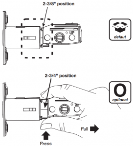
Preparing Door

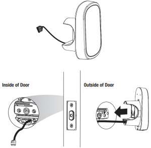
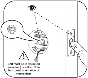
Installing Latch & Strike Plate

Installing Touchscreen Escutcheon
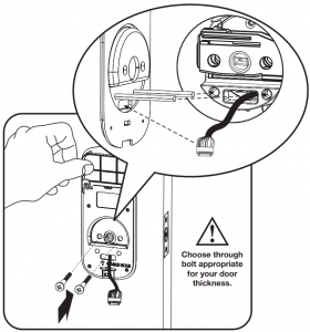
Installing Interior Mounting Plate

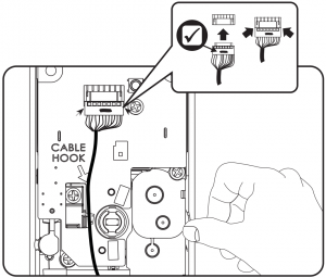
Attaching the Cable Assembly

Installing Interior Escutcheon

Testing Operation

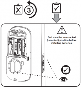
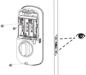
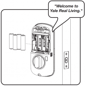
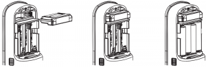
Installing Batteries/Handing the Lock
 Lock automatically adjusts for proper handing.
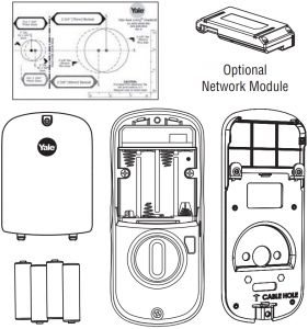
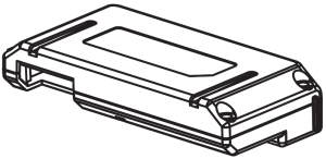
Installing Optional Network Module
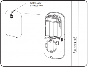
Installing Cover
Congratulations, you’ve installed the Yale Assure Lock ® ® SL Key Free Touchscreen Deadbolt ( )! YRD YRD 256/ 456Continue to Programming Instructions to customize your product.
Programming Instructions

Lock Activation
Master Code must be created before any further programming. PINMax User Codes = 250 with Z-Wave Plus or ZigBee network moduleMax User Codes = 25 without network module or with iM1 network moduleMax User Codes – 12 with Bluetooth
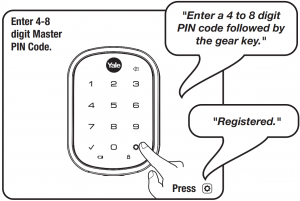
Creating Master PIN Code

Creating User Codes
Master code must be created first. PIN*Max user codes = 250 with Z-Wave Plus or ZigBee network moduleMax user codes = 25 without network module or with iM1 network moduleMax user codes = 12 with Bluetooth


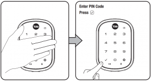
Unlocking Door with PIN Code
Code Chart (Duplicate if necessary)
|
PIN Code Management (With Network Module – Up to 250 Users) |
|||
| User Type |
User Name |
User # |
PIN Code |
| Master | |||
| User | |||
| User | |||
| User | |||
| User | |||
| User | |||
| User | |||
| User | |||
| User | |||
| User | |||
| User | |||
| User | |||
| User | |||
| User | |||
| User | |||
| User |
Resetting Lock to Factory Default
When lock is reset to factory defaults all user codes (including the Master code*) are deleted and all PIN programming features are reset to original default settings (see below).
- Remove the battery cover and batteries.
- Remove the interior escutcheon to access the reset button.
- The reset button (see image at right) is located beside the cable connector. PCB
- While pressing the reset button (minimum of 3 seconds) reinstall batteries. Release reset button.
- Replace battery cover.
Upon reset, Master Code creation is the only option PIN available and must be performed prior to any other programming of the lock.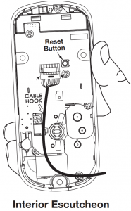
Factory Settings
|
Settings |
Factory Setting |
|
Master PIN Code |
Registration required* |
|
Automatic Re-lock |
Disabled |
|
Inside Indicator Light |
Disabled (Off) |
|
One Touch Locking |
Enabled |
|
Privacy Button Setting |
Disabled |
|
Volume Setting |
Enabled (Low) |
|
Language Setting |
English |
|
Lockout Mode |
Disabled |
|
Automatic Re-lock Time |
30 Seconds |
|
Wrong Code Entry Limit |
5 Times |
|
Shutdown Time |
60 Seconds |
*The Master code must be registered prior to any other programming of the lock.
Definitions
All Code Lockout Mode: This feature is enabled by the Master code. When enabled, it restricts all user (except Master) PIN code access. When attempting to enter a code while the unit is in Lockout, the locked padlock will appear on the RED screen.
Automatic Re-lock Time: After a successful code entry and the unit unlocks, it will automatically re-lock after thirty (30) seconds.
Inside Indicator Light: Located on the interior escutcheon. Shows active status (Locked) of lock and can be enabled or disabled in the (Main Menu selection #3). Advanced Lock Settings Language Setting Mode: Choosing English (1), Spanish (2) or French (3) becomes the (default) setting for the lock’s voice prompts
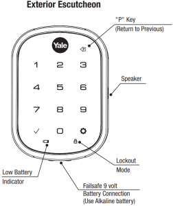
Low Battery: When battery power is low, the Low Battery Warning indicator flashes . If battery power is completely RED lost, use the 9Volt battery override. To use the 9V battery override apply 9V battery, in either direction, to terminals below the touchscreen for backup power option. Wake up the lock and enter your pin code to unlock the door.
Master PIN Code: The Master code is used for programming and for feature settings. It must be created prior to programming the lock. The Master code will also operate (unlock/lock) the lock
Network Module Setting: With the optional Network Module installed, this setting becomes available thru the Main Menu (7) and allows the lock to connect with a network controller.
One Touch Locking: When the latch is retracted, activating the keypad will extend the latch (during Automatic Re-lock duration or when Automatic Re-lock is disabled). When One-Touch Re-lock is in use any valid code will not (disabled), PIN re-lock the lock.
Previous: While in Menu Mode, pressing this icon cancels the current operation and returns the user to the previous step.
Privacy Mode: Privacy mode is disabled by default. Enable Privacy mode by pressing the privacy button for 4 seconds to put the lock in do-not-disturb mode (all pin codes are disabled).
Shutdown Time: The unit will shutdown (flashing ) for sixty (60) seconds and not allow operation after the wrong code RED entry limit (5 attempts) has been met.
Tamper Alert: Audible alarm sounds if attempting to forcibly remove outside lock from door.
User Code: PIN The user code operates the lock. The maximum number of user codes with Z-Wave Plus or ZigBee network module is 250; without network module or with iM1 network module, maximum is 25; with Bluetooth, maximum is 12.Note: When deleting user pin code(s), screen will display user pin code being deleted.
Volume Setting Mode: The volume setting for code verification is set to Low (2) by default; otherwise it can be set to High (1) Silent (3) for quiet areas.
Wrong Code Entry Limit: After five (5) unsuccessful attempts at entering a valid code, the unit will shut down and not PIN allow operation.
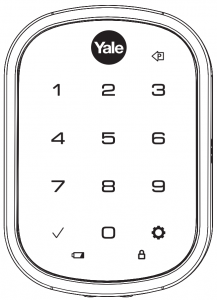
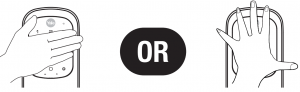
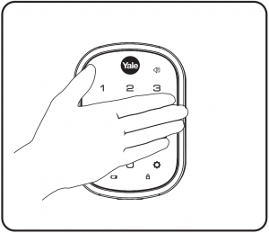
- Touch screen with back of hand or palm to activate.

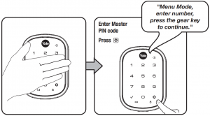
- Enter 4-8 digit master code* followed by key.Lock Response: “Menu mode, enter number, press key to continue.”
- Enter digit corresponding to the function to be performed followed by the key.Follow the voice commands.
*The Master code must be registered prior to any other programming PIN of the lock.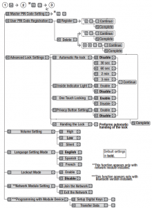
Programming Troubleshooting
| Symptom | Suggested Action |
|
Lock does not respond – door is open and accessible. |
|
| Lock does not respond – door is locked and inaccessible. |
|
| Unit is on for a while then shows no reaction. Lights dim. |
|
| Unit chimes to indicate code acceptance, but the door will not open. |
|
| Unit operates to allow access, but will not automatically re-lock. |
|
|
PIN codes will not register. |
|
| Upon entering a PIN code and pressing |
|
| Upon entering a PIN code and pressing the |
|
| The unit operates, but it makes no sound. |
|
| The unit responds ” Low Battery” |
|
| Upon entering a PIN code and pressing the |
|
* When batteries are replaced, Network Module locks have a real time clock that will be set through the User Interface (UI ); it is recommended to verify correct date and time UI particularly those locks operating under Daylight Saving Time (DST).** Network Module locks only
Hardware Troubleshooting
Cycle lock in both the locked and unlocked positions. If problems are found:
| Door is binding
a. Check that door and frame are properly aligned and door is free swinging.b. Check hinges: They should not be loose or have excessive wear on knuckles. |
| Bolt will not deadlock
a. Check for sufficient clearance of the bolt within the strike-side jamb. Correct this by increasing the depth of the pocket for the bolt.b. Check for misalignment of bolt and/or strike which may be preventing bolt from properly entering the strike. With the door open, extend and retract the bolt; if it is smooth, check the strike alignment. |
| Bolt does not extend or retract smoothly
a. Bolt and strike are misaligned, see above.b. Check the backset of door relative to adjustments already made to bolt.c. Verify proper door preparation and re-bore holes that are too small or misaligned.d. Verify keypad wire harness is routed under the bolt (see Fig. A).e. Verify bolt is installed with correct side up (Fig. A). |
| Keypad numerics are scrolling
Remove interior escutcheon and check to ensure that the wire harness lies flat against the back recessed area and is properly routed along the side of the escutcheon and tucked under the plastic cable guide. |

| NOTE TO INSTALLER AND CONSUMERWhile Yale has included several features to prevent lockout ® (9-Volt battery jumper, low battery warnings), it is still possible for a lockout situation to occur. Because this product does not have a mechanical override (a key), Yale recommends to use ® this product in an environment where there are additional entry points into the dwelling. |
FCC:Class B EquipmentThis equipment has been tested and found to comply with the limits for a Class B digital device, pursuant to Part 15 of the Rules. These limits are designed to provide reasonable protection against harmful interference FCC e in a residential installation. This equipment generates, uses, and can radiate radio frequency energy and, if not installed and used in accordance with the instructions, may cause harmful interference to radio communications. However, there is no guarantee that interference will not occur in a particular installation. If this equipment does cause harmful Interference to radio or television reception, which can be determined by turning the equipment off and on, the user is encouraged to try to correct the interference by one or more of the following measures:
- Reorient or relocate the receiving antenna.
- Increase the separation between the equipment and receiver.
- Connect the equipment into an outlet on a circuit different from that to which the receiver is connected.
- Consult the dealer or an experienced radio/ technician for help.
Warning: Changes or modifications to this device, not expressly approved by Yale Security Inc. could void the user’s authority to operate the equipment.
Industry Canada:This Class A digital apparatus meets all requirements of the Canadian Interference Causing Equipment Regulations.
Installing the Z Plus Module
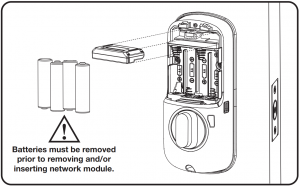
IMPORTANT: the batteries be removed prior must to removing and/or inserting the network module:
- Remove battery cover and batteries.
- Remove and/or insert Network Module.
- Reinstall batteries and battery cover.

Enrolling/Unenrolling the Network Module:
This device is a security enabled Z-Wave Plus product that is able to use encrypted Z-Wave Plus messages to communicate to other security enabled Z-Wave Plus products. This device must be used in conjunction with a Security Enabled Z-Wave Controller in order to fully utilize all implemented functions. This product can be operated in any Z-Wave network with other Z-Wave certified devices from other manufacturers. All non-battery operated nodes within the network will act as repeaters regardless of vendor to increase reliability of the network.
To Enroll/Add the Module (Inclusion Mode):
- Enter the 4-8 digit Master code followed by the key.
- Press the key followed by the key.
- Press the key followed by the key.
To Unenroll/Remove the Module (Exclusion Mode)
- Enter the 4-8 digit Master code followed by the key.
- Press the key followed by the key.
- Press the key followed by the key
Factory Reset – If No Controller:
- See the Lock Installation Manual
- Please use this procedure only when the network primary controller is missing or otherwise inoperable.
For System Integrators: Specific Z-Wave Plus association and parameter information for your lock is available at YaleHome.com/ZwavePlus.
![]() Warning: Changes or modifications to this device, not expressly approved by Yale Security Inc. could void the user’s authority to operate the equipment.
Warning: Changes or modifications to this device, not expressly approved by Yale Security Inc. could void the user’s authority to operate the equipment.
FCC:Contain : U4A- 0 FCC ID YRHCPZW FMModel: 2- YRMZW USThis equipment has been tested and found to comply with the limits for a Class B digital device, pursuant to Part 15 of the Rules. These limits are designed to provide FCC reasonable protection against harmful interference in a residential installation. This equipment generates, uses, and can radiate radio frequency energy and, if not installed and used in accordance with the instructions, may cause harmful interference to radio communications. However, there is no guarantee that interference will not occur in a particular installation. If this equipment does cause harmful Interference to radio or television reception, which can be determined by turning the equipment off and on, the user is encouraged to try to correct the interference by one or more of the following measures:
- Reorient or relocate the receiving antenna.
- Increase the separation between the equipment and receiver.
- Connect the equipment into an outlet on a circuitdifferent from that to which the receiver is connected.
- Consult the dealer or an experienced radio/TV technician for help.
THIS DEVICE COMPLIES WITH PART OF THE FCC RULES 15 . OPERATION IS SUBJECT TO THE FOLLOWING TWO CONDITIONS.(1) THIS DEVICE MAY NOT CAUSE HARMFUL INTERFERENCE AND THIS DEVICE MUST ACCEPT ANY , (2) INTERFERENCE RECEIVED INCLUDING INTERFERENCE , THAT MAY CAUSE UNDESIRED OPERATION.
Industry Canada:Contain: 6982A- 0 IC YRHCPZW FMModel: 2- YRMZW US
Section 7.1.2 of – RSS GENUnder Industry Canada regulations, this radio transmitter may only operate using an antenna of a type and maximum (or lesser) gain approved for the transmitter by Industry Canada. To reduce potential radio interference to other users, the antenna type and its gain should be so chosen that the equivalent isotopically radiated power (e.i.r.p.) is not more than that necessary for successful communication.
Section 7.1.3 of – RSS GENThis Device complies with Industry Canada License-exempt standard(s). RSS Operation is subject to the following two conditions: 1) this device may not cause interference, and 2) this device must accept any interference, including interference that may cause undesired operation of the device.This radio transmitter 6982A- 0 has been YRHCPZW FM approved by Industry Canada to operate with the antenna types listed below with the maximum permissible gain indicated. Antenna types not included in this list, having a gain greater than the maximum gain indicated for that type, are strictly prohibited for use with this device.
Installing the ZigBee Module

IMPORTANT: the batteries be removed prior must to removing and/or inserting the network module:
- Remove battery cover.
- Remove batteries.
- Remove and/or insert network module.
- Reinstall batteries.
- Replace cover.
Enrolling/Unenrolling the Network Module:
This device is a security enabled ZigBee product that is able to use encrypted ZigBee messages to communicate to other security enabled ZigBee products. This device must be used in conjunction with a Security Enabled ZigBee Controller in order to fully utilize all implemented functions. This product can be operated in any ZigBee network with other ZigBee certified devices from other manufacturers. All non-battery operated nodes within the network will act as repeaters regardless of vendor to increase reliability of the network.
To Enroll/Add the Module (Inclusion Mode):
- Enter the 4-8 digit Master code followed by the key.
- Press the key followed by the key.
- Press the key followed by the key.
To Unenroll/Remove the Module (Exclusion Mode)
- Enter the 4-8 digit Master code followed by the key.
- Press the key followed by the key.
- Press the key followed by the key
FCC:Contain : U4A- 0 FCC ID YRHCPZW FMModel: 2- YRMZW USThis equipment has been tested and found to comply with the limits for a Class B digital device, pursuant to Part 15 of the Rules. These limits are designed to provide FCC reasonable protection against harmful interference in a residential installation. This equipment generates, uses, and can radiate radio frequency energy and, if not installed and used in accordance with the instructions, may cause harmful interference to radio communications. However, there is no guarantee that interference will not occur in a particular installation. If this equipment does cause harmful Interference to radio or television reception, which can be determined by turning the equipment off and on, the user is encouraged to try to correct the interference by one or more of the following measures:
- Reorient or relocate the receiving antenna.
- Increase the separation between the equipment and receiver.
- Connect the equipment into an outlet on a circuitdifferent from that to which the receiver is connected.
- Consult the dealer or an experienced radio/TV technician for help.
This equipment complies with radiation exposure FCC limits set forth for an uncontrolled environment. This equipment should be installed and operated with minimum distance 20cm between the radiator and your body. This transmitter must not be co-located or operating in conjunction with any other antenna or transmitter.
This device complies with Part 15 of the rules. FCC Operation is subject to the following two conditions: (1) This device may not cause harmful interference, and (2) this device must accept any interference received, including interference that may cause undesired operation. Any changes or modifications not expressly approved by manufacturer could void the user’s authority to operate the equipment.IMPORTANT! Any changes or modifications not expressly approved by the party responsible for compliance could void the user’s authority to operate this equipment.
Industry Canada:IC YRHCPZB FM : 6982A- 0Model: 2 YRMZBThis Device complies with Industry Canada License-exempt RSS standard(s). Operation is subject to the following two conditions: 1) this device may not cause interference, and2) this device must accept any interference, including interference that may cause undesired operation of the device.
Important Note:Radiation Exposure Statement:This equipment complies with radiation exposure limits IC set forth for an uncontrolled environment. This equipment should be installed and operated with minimum distance 20cm between the radiator and your body.IMPORTANT! Any changes or modifications not expressly approved by the party responsible for compliance could void the user’s authority to operate this equipment.
Installing the Yale iM1 Network Module
IMPORTANT: the batteries be removed prior must to removing and/or inserting the network module:
- Remove battery cover and batteries.
- Remove and/or insert Network Module.
- Reinstall batteries and battery cover.
Enrolling the iM1 Network Module:
The Yale iM1 Network Module must be used with a Yale Assure Lock or Yale nexTouch Lock and cannot be used in conjunction with any other Yale Network Module.
To Enroll the Module:
- Enter the 4-8 digit Master code followed by the key.
- Press the key followed by the key.
- Press the key followed by the key.
Connecting the Yale Secure App with the Yale iM1 Network Module
- After following the steps listed on other side of page for enrolling the module, download the Yale Secure app from the App Store . ®
- Ensure Bluetooth is enabled on your iPhone , iPad or iPod touch , and that you’re within a ® ®® ® foot of your Yale lock.
- Open the Yale Secure app and agree to allow the app to access your Home Data.
- If you do not have a home already created, create a new home when prompted. Tap + to add a new Yale Lock.
- The app will search for your Yale Lock. Be sure that you are within close proximity (less than two feet or so). When “Yale Lock” appears, tap to add.*If the lock does not appear, enter your Master Pin Code on the lock keypad, tap the gear, tap 7, tap gear, tap 1 and then tap gear.
- Scan your Accessory Setup Code; shown below, or manually enter within the app.
Accessory Setup Code
Yale Locks & HardwareProduct Support Tel 1-855-213-5841 • www.yalehome.comYale Locks & Hardware is a division of Yale Security Inc., an ASSA ABLOY Group company
Yale YRD256/ YRD456 Assure Lock SL Key Free Touchscreen Deadbolt Installation and Programming Instructions Manual – Yale YRD256/ YRD456 Assure Lock SL Key Free Touchscreen Deadbolt Installation and Programming Instructions Manual –
[xyz-ips snippet=”download-snippet”]