AES67 Shure Wireless System with Yamaha CL/QL Consoles
WelcomeSince the release of firmware version 4 for Yamaha CL & QL consoles, Shure’s ULXD range of Dante equipped digital wireless mic receivers could be controlled and monitored from the console’s screen. With version 4.1 for CL/QL, the possibilities have increased, with Shure QLXD and Axient wireless mic systems being added to the list of supported devices. Even though these products do not include Dante audio networking, the control data shares the same network, and very little additional setup is required. This document outlines the simple procedure, and provides tips for deploying a successful system. It is assumed that the reader already has some working knowledge and experience with the equipment.
System Requirements
- Yamaha digital mixing console: CL5 / CL3 / CL1 / QL5 / QL1
- Firmware version 4.10 or newer
- Shure digital wireless mic receiver:
- ULXD4D / ULXD4Q / ULXD4 (Firmware version 1.7.34 or newer)
- QLXD4 (Firmware version 1.1.15 or newer)
- Axient AXT400 (Firmware version 1.16.11 or newer), ShowLink access point (when using the ShowLink function with AXT400)
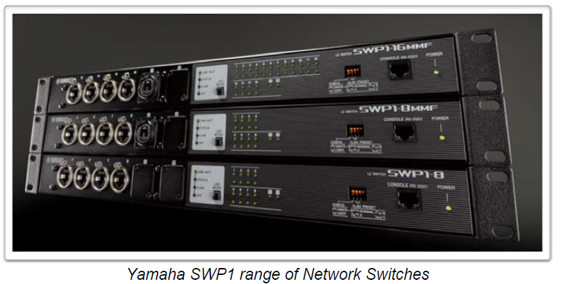
- Network switch, such as the Yamaha SWP1 range
- CAT5e / CAT6 cables
- Computer with Dante Controller software installed (download free of charge from www.audinate.com )
Network Design
In systems with more than 4 items of equipment using Dante, it is best to use at least one network switch. This will allow the lowest network latency to be used, and will be more flexible for organising cable connections. In systems where musicians need to monitor their own performance in real time, this is extra important. Try to use just one switch for interfacing all the audio equipment in the monitor signal chain. The network switch must be suitable for use in Dante networks, with any “Energy Efficient Ethernet” facility disabled. The Yamaha SWP1 range of switches are tried and tested to work well in such systems, and are easier to setup than mostalternatives. All the Dante and Shure wireless devices must be connected in the same VLAN, because even the non-Dante Shure wireless receivers are controlled via the CL/QL console’s Dante connection.
Starting from version 4.10, Yamaha CL/QL consoles support the use of DHCP servers for network device control. Without a DHCP server, all the devices will automatically obtain an IP address in the 169.254.*.* range. This is the default setting for the equipment, so it is the solution that requires the minimum setup time. (Alternatively, the devices can be setup with static IP addresses, though this takes more time to configure). Many Dante devices, including Yamaha CL/QL consoles and Shure ULXD receivers, can support the use of redundant networks: Primary and Secondary. However, this remote control & monitoring function only works in the Primary network. If a Secondary network is constructed, it will provide redundancy for the audio, but not for the control & monitoring.
Non-Dante wireless mic receivers such as Shure ULXD4 and QLXD4 will need an analog connection for audio. For example, connect to the mixer via Yamaha R Series devices such as RSio64-D equipped with MY8-AD96 cards. Shure AXT400 has the additional option of AES/EBU digital audio. This could connect to the Dante network via RSio64-D equipped with an MY16-AE card.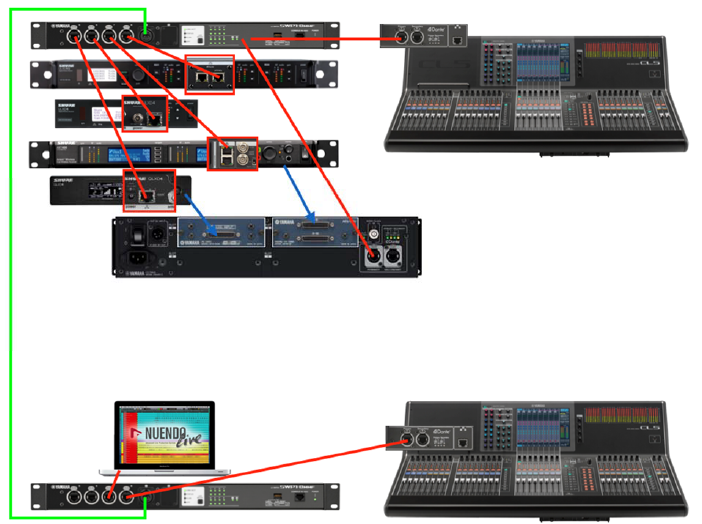
Connect non-Dante Shure ULXD, QLXD and AXT devices to the Dante Primary network. Yamaha RSio64-D can be used to interface with non-Dante audio.
Shure Wireless Mic Receiver Setup
Check the ULXD/QLXD/AXT firmware is up to date. Find the latest versions here: http://www.shure.com/americas/support/downloadsAll these compatible Shure devices have similar front-panel user interfaces. However, the Dante equipped ULXD devices require a little extra configuration before they can be controlled and monitored by a Yamaha CL/QL console:
Shure ULXD Dante Setup
- The device’s Dante name needs to be edited so it begins with the format “Y0**”, where ** is a hexadecimal number between 01 and FF.
- Push the Control encoder on the front panel to enter the menu, and select DEVICE UTILITIES.
- Then scroll to NETWORK, and enter.
- Scroll and select DANTE.
- Select “Dev.ID”
- Set the ID MODE to “Yamaha”.
- Set a unique ID number for each Shure ULXD device, starting from “Y001”.
Check the Network Port configuration:
- In the DEVICE UTILITIES->NETWORK menu, select CONFIGURATION.
- Select SWITCHED (default) if using a Daisy-chain connection with the Dante devices, or if using a simple Primary network without redundancy.
- Select REDUNDANT AUDIO if a Dante system with redundancy is required. (this needs 2 separate networks, requiring additional switches and cables).
- Do not use SPLIT mode. This is not compatible with control from the Yamaha consoles.
Check the IP address used for Dante
- In the DEVICE UTILITIES->NETWORK menu, select DANTE.
- Select AUDIO & CNTRL.
- Make sure “Automatic” mode is selected rather than “Manual”. (Unless your Dante networking strategy specifically requires manual IP address setting. However, this would be unusual).
When exiting the menu, the device will reboot if any of the above settings have been changed.
Shure IP Setup
The non-Dante Shure devices don’t have the above settings, so they can be skipped. However, for each Shure device (either with or without Dante), set the preferred IP addressing strategy for their control (Auto / Manual). Note that the Dante equipped ULXD4Q and ULXD4D have two separate IP address settings: one for DANTE, and one for SHURE CONTROL. That is two different IP addresses sharing the same physical network port on the rear of the device.
- “Automatic” IP Address. This is the method used most frequently, due to convenience of setup and easy management:
- For ULXD: in the DEVICE UTILITIES->NETWORK menu, select SHURE CONTROL, and then NETWORK. For QLXD: hold down the ENTER button and press MENU to enter the advanced menu. Press MENU again to access the IP menu. For AXT: press the UTILITY menu button, followed by NETWORK.
- The Mode is set to “Automatic” by default (“Au” for QLXD), and this is the easiest setting to use.
- If there is no DHCP server in the network, the IP address will be in the range 169.254.*.* (where * is any number between 0 and 254).
- If a DHCP server is in use (some Wi-Fi routers act as DHCP servers), then the IP address will be in a different range, such as “10.0.1.*” or perhaps “192.168.1.*”. There are many possibilities, but the IP address will be provided automatically, depending on the setting of the DHCP server.
- The SUB number will be set automatically. If there is no DHCP server, it will be 255.255.0.0.
- The GW number stands for “Gateway address”. It may show “0.0.0.0” without a DHCP server. If it shows a different number, it will have been set by a DHCP server.
- “Manual” IP address. This is a rarely used method, though offers the potential for tighter security policies in a carefully managed network:
- For ULXD: in the DEVICE UTILITIES->NETWORK menu, select SHURE CONTROL, and then NETWORK. For QLXD: hold down the ENTER button and press MENU to enter the advanced menu. Press MENU again to access the IP menu. For AXT: press the UTILITY menu button, followed by NETWORK.
- Set the Mode to “Manual” (ULXD, AXT) or “Static” (“St” is displayed by QLXD).
- Set the IP address of each Shure device, and the Yamaha CL/QL mixer, to a number within the same subnet (same range of numbers). For example, 192.168.0.*, where each device has a different last number (* is between 2 and 253).
- Set the SUB number to define the size of the subnet. For example, 255.255.255.0 is often used, allowing up to 255 devices in the subnet.
- Set the GW (Gateway Address). In most networks, this is the IP address of the router. If there is no router, then use an appropriate value such as 192.168.0.1 (which is a unique number in the same subnet as the device’s IP address).
Yamaha CL / QL Setup
Firstly, check the firmware of the mixer is v4.10 or newer. The latest firmware can be found at http://www.yamahaproaudio.com/global/en/downloads/firmware_software/
NETWORK
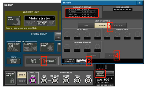
As with the Shure devices, NETWORK settings need to be checked for compatibility before continuing. Use the same IP addressing strategy for CL/QL as with the Shure devices: either “Automatic” or “Manual”. Though CL/QL consoles divide the “Automatic” strategy into two further options: “DHCP” or “AUTO IP”. These enhanced NETWORK settings were introduced with firmware version v4.10. Previously, “AUTO IP” was the only possibility.
- Open the SETUP menu, and the NETWORK window.
- Select the “FOR DEVICE CONTROL” tab. Here the IP address is set for controlling external devices within the Dante network, including the compatible Shure non-Dante devices.
- Choose the required strategy for assigning IP addresses. Select either “DHCP” or “AUTO IP” if the Shure devices have been set to “Automatic” mode:
- “DHCP” if a DHCP server is used in the network. Then the IP settings will be assigned automatically within a range specified by the DHCP server.
- “AUTO IP” for easy setup when a DHCP server is not used. Then the IP address will be set within the 169.254.*.* range, with subnet mask 255.255.0.0.
- “STATIC IP” for manual setup. Choose this when all the Shure devices are set to “Manual” mode. Set an appropriate IP address, subnet mask and gateway address which is compatible with all the other devices in the network.
- Press “APPLY” to confirm the setting. The console must be restarted to complete any change.Note: Before continuing, make sure the IP address set in the FOR MIXER CONTROL tab of the NETWORK SETUP window is in a different subnet (number range) to the IP address used for DEVICE CONTROL.Otherwise the device control will not work. For example, if FOR DEVICE CONTROL is set to 169.254.*.*, then it is safe to use the default setting of 192.168.0.128 for MIXER CONTROL. 169.254.*.* should not be used for both.
 DANTE SETUPThe next task with the digital mixer is to check the Dante setup and Word Clock selection:
 - Open the SETUP menu, and the WORD CLOCK window.
- Check that the master clock is running at 48kHz. The default Clock selection is “DANTE 48k”, which is usually ideal.
- Open the DANTE SETUP window in the SETUP menu.
- In the SETUP tab, check that the console has an ID number (ID #1 is the default). If there is only one CL/QL console in the system, then it must have ID #1. If there is more than one console, then they must each have a different number, though one of them must have #1.
- DANTE PATCH BY: THIS CONSOLE should be enabled. This is the default setting when ID #1 is set.
- If the console is used with live musicians using in-ear monitors, then it is best to set the latency to 0.25ms.
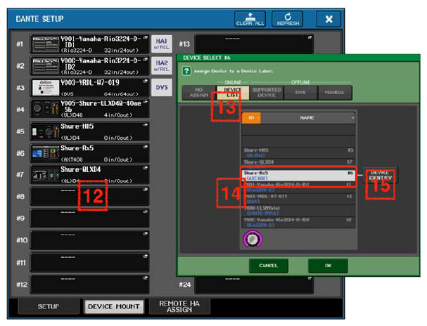
- Now move to the DEVICE MOUNT tab in the DANTE SETUP window.
- In the DEVICE MOUNT window, there is space for 24 devices to be mounted. Once mounted, Dante patching and control can be accessed. Even the non- Dante Shure devices should be mounted here, because they will be controlled via the console’s Dante port. Touch a blank space to open the DEVICE SELECT pop-up.
- Select to view the ONLINE DEVICE LIST.
- Select a Shure device: a ULXD4D/Q should have a name beginning with “Y0**”, where ** is a hexadecimal number. Each compatible device type should be listed with its model name in blue.
- Use the “DEVICE IDENTIFY” button to make the front panel lights flash on the selected device. Touch “OK” at the bottom of the pop-up.
- Do the same for the other compatible Shure devices. Up to 24 devices can be mounted. Then close the DANTE SETUP window.I/O DEVICENext, the Dante devices (including Shure ULXD4D, ULXD4Q) should be patched to the Dante inputs of the CL/QL mixer.
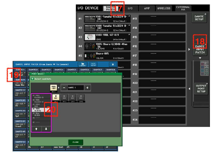
- Open the I/O DEVICE menu, and select the DANTE PATCH tab at the top-left of the screen. All the mounted devices are shown.
- Open the DANTE INPUT PATCH window, to patch audio from the Dante equipped input devices to the CL/QL mixer’s 64 Dante inputs. (32 Dante inputs for QL1).
- Choose which Dante input should be used by the first wireless mic channel. Touch to open the PORT SELECT pop-up.
- Select the ULXD4D/Q device in the left column, then choose which channel is going to be assigned to that Dante input.
- Touch “CLOSE” and then assign the other inputs in turn.
 DANTE SETUPThe next task with the digital mixer is to check the Dante setup and Word Clock selection:
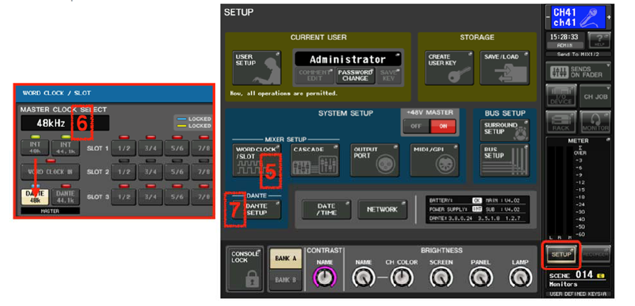

If the non-Dante Shure devices (including AXT400, QLXD4, ULXD4) have audio connections to Dante devices such as Rio3224-D or RSio64-D, then make the relevant Dante patch in this window. At a later stage, this patch will need to be associated with the remote control function.
Using Dante Controller
Dante Controller software is free to download for Windows and Mac OS, from www.audinate.com. It can be used to monitor and edit the settings of Dante devices, and to change audio patching. It may be quicker to use this software to make a lot of patch changes, than to use the CL/QL console. Connect the computer to the Dante network, either via a network switch, or at one end of the daisy-chain. The computer should have its network configuration set to automatic mode. Then, when Dante Controller is launched, it should detect all the Dante devices and display their status. Routing can be made between devices in the Routing tab. Latency status can be seen in the Network Status tab.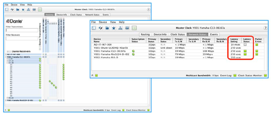 However, to change the latency setting, the Device View window must be opened: either use the Device menu, or double-click on the device’s name. The Latency canbe changed in the Device Config tab. 1ms is the default setting which can be used with many types of network. 250usec is the best choice when the microphones are used by musicians with in-ear monitor systems.
Tip: Both ULXD4D/Q and CL/QL devices have switches built in, so only one additional network switch should be used in between these devices with 250usec latency selected.
Wireless Control from CL/QL
Now the whole system is ready for control and monitoring. Follow these steps on the CL/QL console:
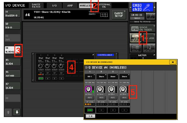
- Open the I/O DEVICE menu
- Take a look at the WIRELESS tab
- Select the required ULXD/QLXD/AXT device from the left column. Press and hold to make the front panel LEDs flash (for easy identification of the device).
- The device details will be shown on the console screen, with a blue “CONTROLLABLE” indicator. Touch the area of the controls to open the I/O DEVICE pop-up window.
- Edit the receiver channel’s name, the RX.GAIN (receiver gain), and the MUTE status. Monitor the transmitter frequency, RF LEVEL and battery level.
- Note: AXT includes additional TX.GAIN and TX NAME functions. QLXD doesn’t include the MUTE function.Tip: Note that the Shure device control parameters correspond only to real-time operation and monitoring, and are not stored or recalled in the scene. If you want to synchronize the scene recall with the gain change, you need to use DIGITAL GAIN in the console. Furthermore, the wireless mic settings can be accessed directly from the console’s input channels. But first the input port must be assigned to the input channel. With Dante devices, this is simple: patch the Dante input port to the Input Channel.Input Channel Control of ULXD4D/Q In the example below, the ULXD4Q is patched to the console’s Dante input ports 41- 44, and these Dante ports are patched to input channels 41-44. So when viewing input channels 41-48 on the HOME OVERVIEW screen, the ULXD information is displayed in the input area at the top. And when taking a look at the SELECTED CH VIEW for input 41, the receiver information is displayed. Touch the RX.GAIN parameter on the screen twice to open the GAIN / PATCH popup window.Whenever the console patch is changed, the ULXD settings will follow the Dante patch to appear on the assigned channel. If there are additional CL/QL consoles in the Dante network, the UXLD4D/Q devices can be mounted to as many as four consoles, and monitored from multiple locations. The DIGITAL GAIN in the receiver can be controlled for the ULX-D and QLX-D. TX. GAIN, which is the ANALOG GAIN before A/D in the transmitter, can be controlled for AXT.Input Channel Control of ULXD4 / QLXD4 / AXT400Because these devices don’t use Dante, an additional step is needed to provide control functions from the input channel.
- Back in the I/O DEVICE menu, WIRELESS tab, select the device from the left-side of the screen.
- Open the I/O DEVICE pop-up by touching the control area in the centre of the screen.
- Touch the PORT ASSIGN tab at the bottom of the window.
- Select which input port is being used to bring the wireless microphone’s audio into the console. It could be a Dante port (if using Rio3224-D or RSio64-D as an audio interface for example), a SLOT port, or an OMNI input on the rear of the console.Now, when the chosen input port is patched to an input channel, the wireless receiver settings will be shown on that channel. In the example below, a QLXD4 is assigned to Dante port 3, which is patched to input channel 3. And an AXT400 receiver is assigned to Dante port 5, which is patched to input channel 5.Notice that both the input’s A.GAIN and the wireless receiver’s gain/level are shown in the GAIN / PATCH pop-up window, if the assigned port has a Head-Amp. So the A.GAIN function would be missing if an AES/EBU connection was used from AXT400. The QLXD4 and ULXD4 devices have the RX.GAIN function, while AXT400 has TX.GAIN and RX.LEVEL. TX.GAIN is the “transmitter gain”, and can only becontrolled if the Shure ShowLink® function is active (which is available only when the ShowLink® access point is connected in the AXT system). Up to 4 CL/QL consoles can be used in the same network to control these Shure wireless devices. Give each CL/QL console a different ID number in the DANTE SETUP menu.
 Tip: Note that the Shure device control parameters correspond only to real-time operation and monitoring, and are not stored or recalled in the scene. If you want to synchronize the scene recall with the gain change, you need to use DIGITAL GAIN in the console. Furthermore, the wireless mic settings can be accessed directly from the console’s input channels. But first the input port must be assigned to the input channel. With Dante devices, this is simple: patch the Dante input port to the Input Channel.Input Channel Control of ULXD4D/Q In the example below, the ULXD4Q is patched to the console’s Dante input ports 41- 44, and these Dante ports are patched to input channels 41-44. So when viewing input channels 41-48 on the HOME OVERVIEW screen, the ULXD information is displayed in the input area at the top. And when taking a look at the SELECTED CH VIEW for input 41, the receiver information is displayed. Touch the RX.GAIN parameter on the screen twice to open the GAIN / PATCH popup window.
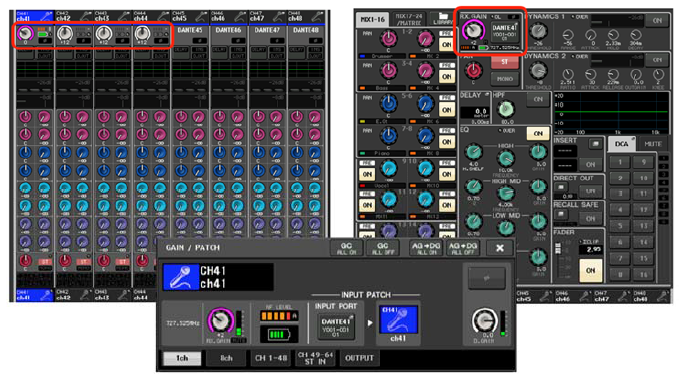 Whenever the console patch is changed, the ULXD settings will follow the Dante patch to appear on the assigned channel. If there are additional CL/QL consoles in the Dante network, the UXLD4D/Q devices can be mounted to as many as four consoles, and monitored from multiple locations. The DIGITAL GAIN in the receiver can be controlled for the ULX-D and QLX-D. TX. GAIN, which is the ANALOG GAIN before A/D in the transmitter, can be controlled for AXT.Input Channel Control of ULXD4 / QLXD4 / AXT400Because these devices don’t use Dante, an additional step is needed to provide control functions from the input channel.
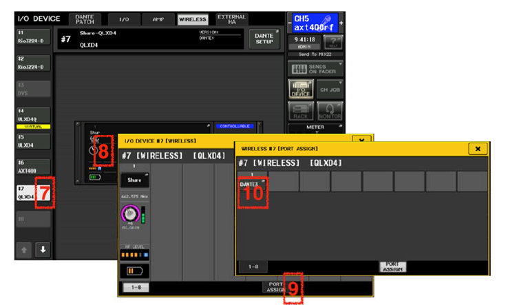 Now, when the chosen input port is patched to an input channel, the wireless receiver settings will be shown on that channel. In the example below, a QLXD4 is assigned to Dante port 3, which is patched to input channel 3. And an AXT400 receiver is assigned to Dante port 5, which is patched to input channel 5.
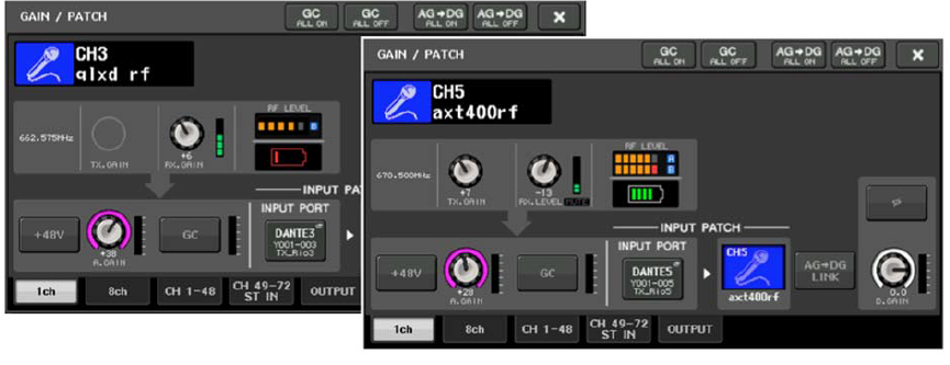 Notice that both the input’s A.GAIN and the wireless receiver’s gain/level are shown in the GAIN / PATCH pop-up window, if the assigned port has a Head-Amp. So the A.GAIN function would be missing if an AES/EBU connection was used from AXT400. The QLXD4 and ULXD4 devices have the RX.GAIN function, while AXT400 has TX.GAIN and RX.LEVEL. TX.GAIN is the “transmitter gain”, and can only becontrolled if the Shure ShowLink® function is active (which is available only when the ShowLink® access point is connected in the AXT system). Up to 4 CL/QL consoles can be used in the same network to control these Shure wireless devices. Give each CL/QL console a different ID number in the DANTE SETUP menu.
Troubleshooting
Dante Controller software is a very helpful trouble-shooting tool for Dante networks. And it is free of charge! Download it at https://www.audinate.com/products/software.If Dante Controller isn’t able to discover all the devices and their settings:
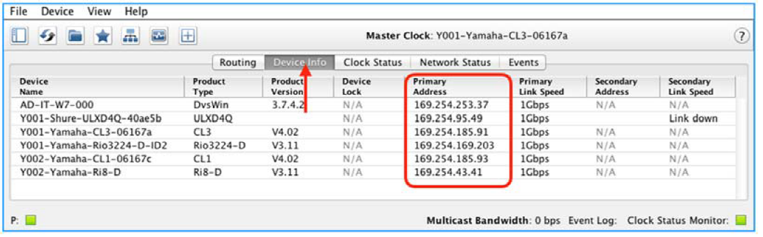
- begin by checking all the device IP addresses, including the computer’s. They can be monitored in the “Device Info” tab of Dante Controller.
- If they are all in automatic mode, they will be using an address starting with 169.254…
- If the addresses begin with different numbers, they are probably set by a DHCP server or Wi-Fi router. Check that all the numbers are compatible: same first sets of numbers, unique last number.
- If some devices have completely different IP addresses, then they probably have been set to “Static” or “Manual” mode. Try resetting them to “Auto” or “DHCP”.
If Dante Controller discovers all the devices and their status, but audio is not able to reach the console from the ULXD4D/Q device:
- Check the Word Clock settings. Set the console to DANTE 48k, and set it as Dante Preferred Master (its default setting).
- Check the console (or another console in the same network) has Device ID#1 in its DANTE SETUP, and the ULXD4D/Q is mounted in the Dante Setup.
- Check the Dante Patch has the ULXD4D/Q outputs routed to the CL/QL inputs.
If audio is working well but the console is unable to control the ULXD4D/Q:
- Check the IP address used by ULXD4D/Q: DEVICE UTILITIES->NETWORK- >SHURE CONTROL->NETWORK. Mode should usually be “Automatic”.
- Check the device firmware is up to date (v4.1 or newer for CL/QL, v1.7.34 or newer for ULXD4D/Q).
- Check the ULXD4D/Q Dante Device ID begins with “Y0**”, where ** is a hexadecimal number between 01 and FF.
- Check the CL/QL SETUP->NETWORK menu. The IP address for MIXER CONTROL must be in a different subnet (number range) to the IP address for DEVICE CONTROL.
- Check if the network switch is using a feature called “IGMP Snooping”. In some rare cases (depending on switch type and device firmware versions) this can block the control data while allowing audio. Test with a different switch, or disable IGMP Snooping if you know how. However, note that disabling “IGMP Snooping” has the potential to restrict other aspects of the network’s performance. Consult with a network specialist before proceeding.
- Yamaha SWP1 switches are known to work correctly with their “DANTE CONFIG” enabled. Use these for a more stable and reliable experience. They include the “IGMP Snooping” function which is automatically setup by default, as well as providing some additional useful network monitoring tools.If the Shure wireless receiver is discovered by CL/QL, but is not controllable:
- Check if some other consoles or software are already controlling the devices. Control is limited to 4 CL/QL consoles.
- Check if all the IP addresses are in a compatible range.
- Check the CL/QL SETUP->NETWORK menu. The IP address for MIXER CONTROL must be in a different subnet (number range) to the IP address for DEVICE CONTROL.
- Check if the PORT ASSIGN has been made correctly (see page 12 above).
- Check all the device firmware is up to date: CL/QL consoles, R series devices, Shure wireless devices.
 If the Shure wireless receiver is discovered by CL/QL, but is not controllable:
Reference Websites
www.yamahaproaudio.comwww.shure.comwww.audinate.comVideo about controlling Shure receivers from Yamaha CL/QL consoles:https://www.youtube.com/watch?v=6Cj2jhbkPSEhttps://www.youtube.com/watch?v=N0bTpP5nrCA![]()
[xyz-ips snippet=”download-snippet”]