
YAMAHA Ceiling Microphone RM-CG Installation Guide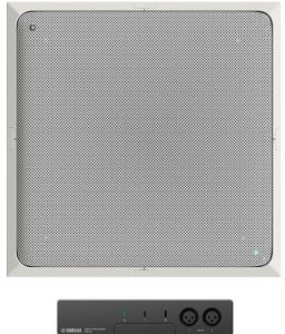
PRECAUTIONSPLEASE READ CAREFULLY BEFORE PROCEEDING
Please keep this manual in a safe place for future reference.
Yamaha cannot be held responsible for damage caused by improper use or modifications to the product, or data that is lost or destroyed.
![]() WARNING
WARNING
Always follow the basic precautions listed below to avoid the possibility of serious injury or even death from electrical shock, short-circuiting, damages, fire or other hazards. These precautions include, but are not limited to, the following:
Fire warning
- Do not place any burning items or open flames near the product, since they may cause a fire.
Hearing loss
- Before turning the power of all devices on or off, make sure that all volume levels are set to the minimum. Failing to do so may result in hearing loss, electric shock, or device damage.
- When turning on the AC power in your audio system, always turn on the power amplifier LAST, to avoid hearing loss and speaker damage. When turning the power off, the power amplifier should be turned off FIRST for the same reason.
Location and connection
- Always consult a professional installer if the product installation requires construction work, and make sure to observe the following precautions.
- Choose mounting hardware and an installation location that can support the weight of the product.
- Avoid locations that are exposed to constant vibration.
- Use the required tools to install the product.
- Inspect the product periodically
![]() CAUTIONAlways follow the basic precautions listed below to avoid the possibility of physical injury to you or others, or damage to the device or other property. These precautions include, but are not limited to, the following:
CAUTIONAlways follow the basic precautions listed below to avoid the possibility of physical injury to you or others, or damage to the device or other property. These precautions include, but are not limited to, the following:
If you notice any abnormality
- If any of the following problems occur, immediately turn off the PoE injector or the PoE network switch and disconnect the cable.
- The LAN cable damaged.
- Unusual smells or smoke are emitted.
- Some object, or water has been dropped into the product.
- There is a sudden loss of sound during use of the product.
- Cracks or other visible damage appear on the product.Then have the product inspected or repaired by qualified Yamaha service personnel.
Location and connection
- When connecting this product with a PoE injector or the PoE network switch, use a CAT5e or higher LAN cable, which supports the maximum power supply voltage (57 V) of the IEEE 802.3at standard. If you connect a cable that does not comply with specifications, or connect a flat type or slim type cable, fire or malfunctions might occur.
- Do not damage the LAN cable. Failure to observe this precaution could result in fire, electric shock, or damage to the product.
- Do not place heavy objects on the cable.
- Do not process the cable in any way.
- Do not use staples to fix the cable in place.
- Do not apply excessive force to the cable.
- Be sure to keep the cable away from anything hot.
- Do not place the product in an unstable position or a location with excessive vibration, where it might accidental fall and cause injury.
- Keep this product out of reach of children. This product is not suitable for use in locations where children are likely to be present.
- When installing the product:
- Do not cover it with any cloth.
- Make sure the top surface faces up; do not install on its sides or upside down.
- Do not use the product in a confined, poorly ventilated location. Inadequate ventilation can result in overheating, possibly causing damage to the product(s), or even fire.
- Do not place the product in a location where it may come into contact with corrosive gases or salt air. Doing so may result in malfunction.
- Before moving the product, remove all connected cables.
- Do not route cables where someone might trip over them, such as in a location where people pass. Tripping on a cable may cause a person or this product to fall down, resulting in personal injury or damage to the product.
Do not open
- This product contains no user-serviceable parts. Do not attempt to disassemble the internal parts or modify them in any way.
Water warning
- • Do not expose the product to rain, use it near water or in damp or wet conditions, or place on it any containers (such as vases, bottles or glasses) containing liquids which might spill into any openings.
- Never insert or remove a cable with wet hands.
Installation
For recessing into the ceiling, refer to the procedure on the back page.
![]() WARNING:
WARNING:
- Before installing, confirm that the locations where the unit and the safety wire are to be installed are strong enough.
- For the following work, use a safety wire, and be careful not to fall or cause the unit or surrounding structures to be dropped or damaged.
NOTICE
- To supply power, confirm that the unit is securely installed, and then connect the LAN cable to a PoE injector or PoE network switch that complies with IEEE802.3af.
- Cables up to a maximum length of 100 m can be used.
- In order to prevent electromagnetic interference, use STP (shielded twisted pair) cables.
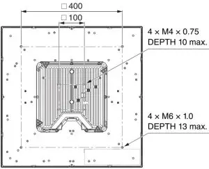
When using a VESA mounting bracket for ceiling mounting
Prepare a VESA100-compatible mounting bracket and mounting screws.For details on attaching the VESA mounting bracket, refer to its manual. The following is an example.If the terminal cover will not be used, skip steps 1 and 2–1, 8 and 10 on the back side. However, the dustproofness and plenum ratings will not be met.
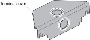
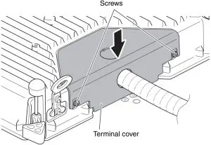
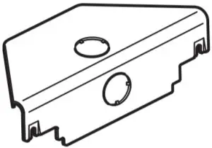
- Make a hole in the terminal cover to pass the conduit through.Make a cable hole in the terminal cover according to the orientation of the conduit. The cable hole can be made in the terminal cover horizontally or vertically.We recommend using nippers. The terminal cover may become deformed if you try to make the hole by hitting or prying the cover with a flathead screwdriver, etc.
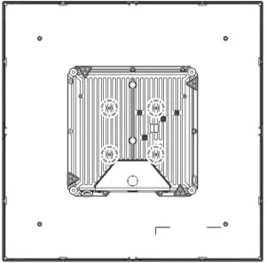
- Attach the VESA mounting bracket to the unit by using the screw holes shown below.

- Attach the VESA mounting bracket to the ceiling.For the remainder of the procedure, continue with steps 2–6 to 2–10 and step 4 on the back side.
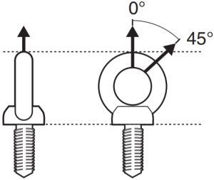
When hanging with wiresPrepare wires and eyebolts (M6 × 13 mm or less) with sufficient load capacity for hanging.NOTE:Use eyebolts that meet local regulations and safety standards.NOTICE:The strength of an eyebolt depends on its installation angle. Install an eyebolt within a range of 0° to 45° from vertical.
If the terminal cover will not be used, skip steps 1 and 2 -1, 8 and 10 on the back side. However, the dust proofness and plenum ratings will not be met.
- Make a hole in the terminal cover to pass the conduit through.Make a cable hole in the terminal cover according to the orientation of the conduit. The cable hole can be made in the terminal cover horizontally or vertically.We recommend using nippers. The terminal cover may become deformed if you try to make the hole by hitting or prying the cover with a flathead screwdriver, etc.
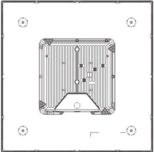
- Install the eyebolts into the unit by using the screw holes shown below.
- Install the unit by attaching it to the wires hanging from the ceiling, making sure that the unit is horizontal.For the remainder of the procedure, continue with steps 2–6 to 2–10 and step 4 on the back side.
When recessing into the ceiling![]() WARNING:
WARNING:
- Before installing, confirm that the locations where the unit and the safety wire are to be installed are strong enough.
- Attach the unit to the ceiling by using the included brackets. Before installing, confirm that the mounting location is strong enough. In addition, make sure that the ceiling panel will not be subjected to a load higher than the withstand load, such as by using the included U-shaped bracket to transfer the load onto structural material. If a load will be applied to the panel, reinforce the panel as necessary in order to prevent parts from being damaged and the unit or parts from falling.
NOTICE:
- To supply power, confirm that the unit is securely installed, and then connect the LAN cable to a PoE injector or PoE network switch that complies with IEEE802.3af.
- Cables up to a maximum length of 100 m can be used.
- In order to prevent electromagnetic interference, use STP (shielded twisted pair) cables.
- The weight, including the grille and mounting brackets, is approximately 6.8 kg.
- Making a hole in the ceiling
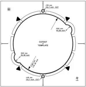
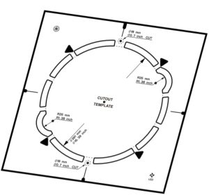
- Position the cutout template on the ceiling, and then mark the cutout locations.Determine the location and orientation based on the position of the logo.The thick lines indicate parts that are to be cut out.NOTE:When using a hole cutter, mark the center points of the five holes to be cut according to the cutout template. First cut the R35 mm holes.Make sure that there will be ceiling rails on the top and bottom sides of the cutout template when it is oriented as shown below.
- Cut holes in the ceiling along the markings. CAUTION:Be careful not to get debris or dust in your eyes when cutting holes.
- Position the cutout template on the ceiling, and then mark the cutout locations.Determine the location and orientation based on the position of the logo.The thick lines indicate parts that are to be cut out.NOTE:When using a hole cutter, mark the center points of the five holes to be cut according to the cutout template. First cut the R35 mm holes.Make sure that there will be ceiling rails on the top and bottom sides of the cutout template when it is oriented as shown below.
- Attaching the bracketsIf the terminal cover will not be used, skip steps 1, 8 and 10. However, the dustproofness and plenum ratings will not be met.
- Make a hole in the terminal cover to pass the conduit through.Make a cable hole in the terminal cover according to the orientation of the conduit. The cable hole can be made in the terminal cover horizontally or vertically.We recommend using nippers. The terminal cover may become deformed if you try to make the hole by hitting or prying the cover with a flathead screwdriver, etc.
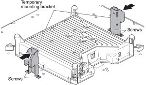
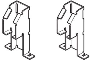
- After loosening the temporary mounting brackets screws on the unit, attach the temporary mounting brackets to the unit by using those screws.
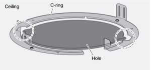
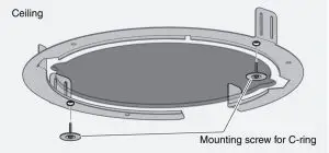
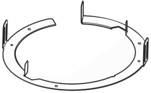
- Insert the C-ring into the hole in the ceiling, and align the notches.
- Secure the C-ring to the ceiling by using themounting screws for the C-ring.
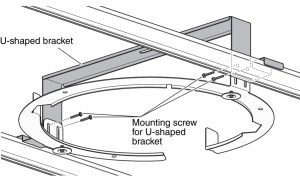
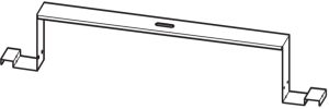
- Insert the U-shaped bracket into the hole in the ceiling, and then secure it to the C-ring by using the mounting screws for the U-shaped bracket.To spread the weight of the unit, make sure that both ends of the U-shaped bracket rest on a ceiling rail.
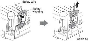
- Attach the safety wire to a structure above the ceiling.
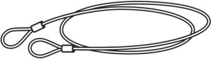
- Attach the safety wire to the safety wire ring, and secure the safety wire and safety wire ring with a cable tie.Perform the following steps up to step 3 with the unit hanging from the safety wire. WARNING:Be sure to take measures to prevent the unit from falling.If the attached safety wire is not long enough, consider the weight of the unit and the installation location when preparing a wire of appropriate length and strength. If the wire is too long, kinetic energy will be applied to the wire when the unit falls, possibly causing the wire to break and the unit to fall.
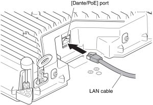
- Pass the LAN cable through the terminal cover.
- Plug the LAN cable into the [Dante/PoE] port.
- After loosening the terminal cover screws on the unit, attach the terminal cover to the unit by using those screws.
- Make a hole in the terminal cover to pass the conduit through.Make a cable hole in the terminal cover according to the orientation of the conduit. The cable hole can be made in the terminal cover horizontally or vertically.We recommend using nippers. The terminal cover may become deformed if you try to make the hole by hitting or prying the cover with a flathead screwdriver, etc.
- Attaching to the ceiling
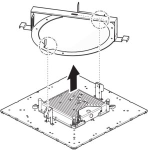
- Align the temporary mounting brackets with the notches of the hole in the ceiling, and then slowly insert the unit through the ceiling.Be careful not to pinch the cable or safety wire between the ceiling and the unit.
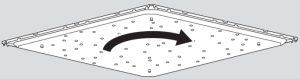
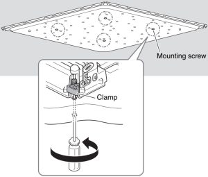
- Turn the unit clockwise to adjust its orientation.Placing the temporary mounting brackets on the C-ring allows you to take your hands off the unit to work.
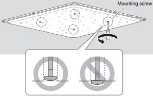
- While holding the unit up, turn the four mounting screws clockwise with a Phillips screwdriver to tighten them.The first turn opens the clamp. Each turn of the screw lowers the clamp and holds the C-ring against the ceiling.If it is difficult to open the clamp, turn the screw counterclockwise half a turn to make it easier for the clamp to open.The orientation of the unit may shift when the mounting screws are turned. If the unit becomes misaligned, correct its position before fully tightening the screws.WARNING:
- Do not overtighten the mounting screws, otherwise they or the clamp may break.
- Do not turn any screws other than the mounting screws. Otherwise, the unit may fall or malfunction.
- Attaching the grille
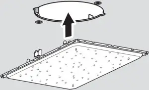
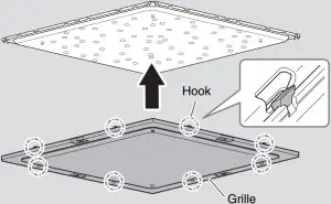
- Attach the grille to the unit.Attach while lightly opening the 8 hooks on the grille outward.
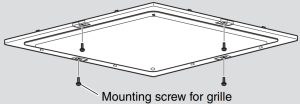
- Secure the grille at four locations by using its mounting screws.
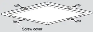
- Slide the four screw covers from the side so they fit in their positions.For removal, reverse the procedure. In that case, note the following.
- When removing the grille, lightly open the hooks outward.
- Loosen the four mounting screws by turning them counterclockwise. When the screw is loosened, the clamp that holds the unit against the ceiling will rise and close in. Make sure that the screw head does not protrude from the surface. If the screw is loosened too much, the clamp will come off, possibly falling and causing injuries when the unit is being removed from the hole.
- Attach the grille to the unit.Attach while lightly opening the 8 hooks on the grille outward.
- Align the temporary mounting brackets with the notches of the hole in the ceiling, and then slowly insert the unit through the ceiling.Be careful not to pinch the cable or safety wire between the ceiling and the unit.
 For removal, reverse the procedure. In that case, note the following.
Bundled items
- Ceiling Microphone (1)
- Grille (1)
- Mounting screw for grille (M3×8 mm) (5)
- Screw cover (4)
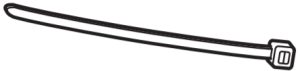
- Cable tie (1)
- Terminal cover (1)
- Safety wire (1)
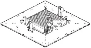
- U-shaped bracket (1)
- Mounting screw for U-shaped bracket (M4×20 mm) (5)
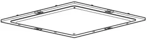
- C-ring (1)
- Cutout template (1)
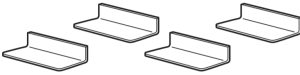
- Temporary mounting bracket (2)

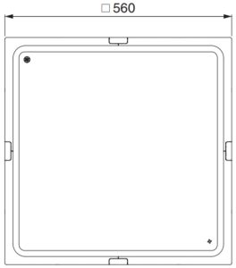
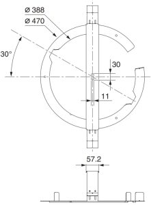
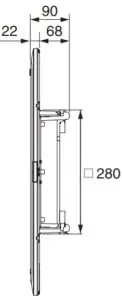
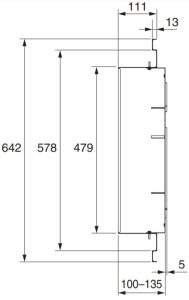
Dimensions
NOTICETo avoid the possibility of malfunction/damage to the product or damage to other property, follow the notices below. Handling and maintenance
- Do not connect this product to public Wi-Fi and/or Internet directly.Only connect this product to the Internet through a router with strong password-protections. Consult your router manufacturer for information on security best practices.
- Do not use the product in the vicinity of a TV, radio, or other electric products. Otherwise, the product, TV, or radio may generate noise.
- Do not expose the product to excessive dust or vibration, or extreme cold or heat, in order to prevent the possibility of disfiguration, unstable operation, or damage to the internal components.
- Do not install in locations where temperature changes are severe. Otherwise, condensation may form on the inside or the surface of the product, causing it to break.
- If there is reason to believe that condensation might have occurred, leave the product for several hours without turning on the power until the condensation has completely dried out, in order to prevent possible damage.
- Do not place vinyl, plastic or rubber objects on the product, since this might cause alteration or discoloration.
- When cleaning the product, use a dry and soft cloth. Do not use paint thinners, solvents, cleaning fluids, or chemical impregnated wiping cloths, since this might cause alteration or discoloration.
- Do not place the face down with the grille attached, as deformation of the grille may result.
ACCESSORIES
(For details on the shapes, refer to the back page.)
- Installation Manual (this manual) (1)
- Grille (1)
- Mounting screw for grille (M3 × 8 mm) (5*)
- Screw cover (4)
- Cable tie (1)
- Terminal cover (1)
- Safety wire (1)
- U-shaped bracket (1)
- Mounting screw for U-shaped bracket (M4 × 20 mm) (5*)
- C-ring (1)
- Mounting screw for C-ring (2)
- Cutout template (1)
- Temporary mounting bracket (2)* Includes one spare.
SPECIFICATION
General
|
Description |
Ceiling Microphone | |
| Color |
Black, White |
|
|
Dimensions (W × D × H) |
W560 mm × D560 mm × H90 mm (including protrusions/microphone panel: H22 mm) | |
| Weight |
5.6 kg (including grille) |
|
|
Power requirements |
PoE (IEEE802.3af), DC 48 V | |
| Maximum Power Consumption |
7.2 W |
|
|
In Operation |
Temperature | 0 °C – 40 °C |
| Humidity |
30% – 90% (No condensation) |
|
|
Storage |
Temperature | −20 °C – 60 °C |
| Humidity |
20% – 90% (No condensation) |
|
|
Indicator |
|
|
|
Mount |
|
|
|
Maximum device number with RM-CR |
2 |
|
|
Dust Protection |
IP5X for dust protection (with Terminal cover) | |
| Plenum Rating |
UL2043 (with Terminal cover) |
Network
|
[Dante/PoE] port |
Dante, Remote Control, WebUI, PoE Cable Requirements: CAT5e or higher, STP |
Audio
|
Frequency response |
160 Hz – 16 kHz (−10 dB) |
|
|
Sampling Rate |
48 kHz | |
| Bit depth |
24 bit |
|
|
Latency |
58 [ms] (including signal processing) | |
| Audio I/O | Dante |
1in × 2out In1=AEC reference signal/ Out1=output of beam mix, Out2= output of beam mix (simple processed) |
|
Maximum input level of SPL (0 dBFS) |
117.8 dB SPL | |
| Self Noise |
−0.8 dBA SPL |
|
|
SNR (Ref. 94 dB SPL at 1 kHz) |
94.8 dBA | |
| Sensitivity |
−23.8 dBFS/Pa |
|
|
Dynamic Range |
118.6 dBA | |
| Signal Processing |
Multi beam tracking, Adaptive Echo Canceler, Noise Reduction, Dereverberation, Auto Mixer, Auto Gain Control, Parametric EQ, Output Gain |
INFORMATION
About functions/data bundled with the product
- This is a class A product. Operation of this product in a residential environment could cause radio interference.
- Refer to the website below for the licensing terms of the open source software used in this product.U.S.A. and Canadahttps://uc.yamaha.com/support/Other Countrieshttps://download.yamaha.com/
- This product uses Dante Ultimo.Refer to the Audinate website (English) for details on the open source licenses for the particular software.https://www.audinate.com/software-licensing
About this manual
- The illustrations as shown in this manual are for instructional purposes only.
- The company names and product names in this manual are the trademarks or registered trademarks of their respective companies.
- Software may be revised and updated without prior notice.
- The contents of this manual apply to the latest specifications as of the publishing date. To obtain the latest manual, access the Yamaha website then download the manual file.
About disposal
- This product contains recyclable components. When disposing of this product, please contact the appropriate local authorities.
FCC INFORMATION (U.S.A.)
- IMPORTANT NOTICE: DO NOT MODIFY THIS UNIT!This product, when installed as indicated in the instructions contained in this manual, meets FCC requirements. Modifications not expressly approved by Yamaha may void your authority granted by the FCC, to use the product.
- IMPORTANT: When connecting this product to accessories and/or another product use only high quality shielded cables. Cable/s supplied with this product MUST be used. Follow all installation instructions. Failure to follow instructions cold void your FCC authorization to use this product in the USA.
- NOTE: This equipment has been tested and found to comply with the limits for a Class A digital device, pursuant to Part 15 of the FCC rules. These limits are designed to provide reasonable protection against harmful interference when the equipment is operated in a commercial environment.This equipment generates, uses and can radiate radio frequency energy and, if not installed and used in accordance with the instruction manual, may cause harmful interference to radio communications. Operation of this equipment in a residential area is likely to cause harmful interference in which case the user will be required to correct the interference at his own expense.
COMPLIANCE INFORMATION STATEMENT
(Supplierʼs declaration of conformity procedure)
Responsible Party: Yamaha Unified Communications, Inc.Address: 144 North Rd, Suite 3250 Sudbury, MA 01776Telephone: 800-326-1088Type of Equipment: Ceiling MicrophoneModel Name: RM-CG
This device complies with Part 15 of the FCC Rules.Operation is subject to the following conditions:
- this device may not cause harmful interference, and
- this device must accept any interference received including interference that may cause undesired operation.
![]() Information for users on collection and disposal of old equipment:This symbol on the products, packaging, and/or accompanying documents means that used electrical and electronic products should not be mixed with general household waste.For proper treatment, recovery and recycling of old products, please take them to applicable collection points, in accordance with your national legislation.By disposing of these products correctly, you will help to save valuable resources and prevent any potential negative effects on human health and the environment which could otherwise arise from inappropriate waste handling.For more information about collection and recycling of old products, please contact your local municipality, your waste disposal service or the point of sale where you purchased the items.
Information for users on collection and disposal of old equipment:This symbol on the products, packaging, and/or accompanying documents means that used electrical and electronic products should not be mixed with general household waste.For proper treatment, recovery and recycling of old products, please take them to applicable collection points, in accordance with your national legislation.By disposing of these products correctly, you will help to save valuable resources and prevent any potential negative effects on human health and the environment which could otherwise arise from inappropriate waste handling.For more information about collection and recycling of old products, please contact your local municipality, your waste disposal service or the point of sale where you purchased the items.
For business users in the European Union:If you wish to discard electrical and electronic equipment, please contact your dealer or supplier for further information.Information on Disposal in other Countries outside the European Union:This symbol is only valid in the European Union. If you wish to discard these items, please contact your local authorities or dealer and ask for the correct method of disposal.
The model number, serial number, power requirements, etc., may be found on or near the name plate, which is at the bottom of the unit. You should note this serial number in the space provided below and retain this manual as a permanent record of your purchase to aid identification in the event of theft.
Model No._____________Serial No. _____________
Manual Development Group © 2020 Yamaha Corporation Published 12/2020 IPES-C0
[xyz-ips snippet=”download-snippet”]