![]()
![]() CHR SeriesSPEAKER SYSTEMOwner’s Manual
CHR SeriesSPEAKER SYSTEMOwner’s Manual
PRECAUTIONS
PLEASE READ CAREFULLY BEFORE PROCEEDING
Please keep this manual in a safe place for future reference.
 WARNING
Always follow the basic precautions listed below to avoid the possibility of serious injury or even death from electrical shock, short-circuiting, damages, fire or other hazards. These precautions include, but are not limited to, the following:
If you notice any abnormality
- If any of the following problems occur, immediately turn off the power of the amplifier.– Unusual smells or smoke is emitted.– Some object, or water has been dropped into the product.– There is a sudden loss of sound during the use of the product.– Cracks or other visible damage appear on the product.Then have the product inspected or repaired by qualified Yamaha service personnel.Do not open
- This product contains no user-serviceable parts. Do not attempt to disassemble the internal parts or modify them in any way.Water warning
- Do not expose the product to rain, use it near water or in damp or wet conditions, or place on it any containers (such as vases, bottles or glasses) containing liquids that might spill into any openings.Fire warning
- Do not place any burning items or open flames near the product, since they may cause a fire.Hearing loss
- Before turning the power of all devices on or off, make sure that all volume levels are set to the minimum. Failing to do so may result in hearing loss, electric shock, or device damage.
- When turning on the AC power in your audio system, always turn on the power amplifier LAST, to avoid hearing loss and speaker damage. When turning the power off, the power amplifier should be turned off FIRST for the same reason.
CAUTION
Always follow the basic precautions listed below to avoid the possibility of physical injury to you or others. These precautions include, but are not limited to, the following:Location and connection
- Do not place the product in an unstable position or a location with excessive vibration, where it might accidentally fall over and cause injury.
- Keep this product out of reach of children. This product is not suitable for use in locations where children are likely to be present.
- Do not place the product in a location where it may come into contact with corrosive gases or salt air. Doing so may result in malfunction.
- Before moving the product, remove all connected cables.
- When transporting or moving the CHR15, always use two or more people. Attempting to lift the product by yourself may result in injuries, such as back injuries, or cause the product to be dropped and broken, which could lead to other injuries.
- Do not use the speaker’s handles for suspended installation. Doing so can result in damage or injury.
- Do not hold the bottom of the product when transporting or moving it. In doing so, you may pinch your hands under the product, and result in injury.
- Do not press the rear panel of the product against the wall. Doing so may cause the plug to come in contact with the wall and detach the cable from the connector, resulting in short-circuiting, malfunction, or even fire.
- Always consult qualified Yamaha service personnel if the product installation requires construction work. Improper installation might cause accidents, injuries, damage, or malfunction of this product.
- Use only speaker cables for connecting speakers to the speaker jacks. The use of other types of cables may result in fire.
Handling caution
- Do not insert your fingers or hands in any gaps or openings on the product (ports).
- Do not rest your weight on the product or place heavy objects on it.
- Make sure that the output power of the amplifier is lower than the power capacity of this product (see page 108). If the output power is not appropriate, a malfunction or fire may occur.
- Do not input excessively loud signals that may result in clipping in the amplifier or cause the following:– Feedback, when using a microphone– Continuous and extremely loud sound from a musical instrument, etc.– Continuous and excessively loud distorted sound– Noise caused by plugging/unplugging the cable while the amplifier is turned on Even if the output power of the amplifier is lower than the power capacity of this product (program), damage to the product, malfunction or fire may occur.
NOTICE
To avoid the possibility of malfunction(damage to the product or damage to other property, follow the notices below.
Handling and maintenance
- Do not expose the product to excessive dust or vibration, or extreme cold or heat, in order to prevent the possibility of panel disfiguration, unstable operation. or damage to the internal components.
- Do not touch the speaker driver unit. since it might cause
- Be sure to observe the amplifier’s rated load impedance (see page 108). particularly when connecting speakers in Connecting an impedance load outside the amplifier’s rated range can damage the amplifier.
- When cleaning the product, use a dry and soft cloth. Do not use paint thinners. cleaning fluids. or chemical-impregnated wiping cloths. since this might cause alteration or discoloration.
- Air blowing out of the bass reflex ports (holes or holes at the front) is normal and often occurs when the speaker is handling program material with heavy bass content.
- Do not place the speaker lace
Protective Circuit
- All full-range loudspeakers are fitted with a self-resetting poly switch that protects the high-frequency driver from damage caused by excessive power. If a loudspeaker cabinet loses high-frequency output. immediately remove power from the power amplifier and wait for two to three This should be long enough to allow the poly switch to reset. Reapply power and check the performance of the high-frequency driver before continuing, with the power reduced to a level that does not cause the poly switch to interrupt the signal.
Information
About this manual
- The illustrations as shown in this manual are for instructional purposes only
- The company names and product names in this manual are the trademarks or registered trademarks of their respective companies.
About disposal
- This product contains recyclable components.
When disposing of this product. please contact the appropriate local authorities.Yamaha cannot be held responsible for damage caused by improper use or modifications to the product.
Information for users on collection and disposal of old equipment:
 This symbol on the products, packaging, and/or accompanying documents means that used electrical and electronic products should not be mixed with general household waste.For proper treatment, recovery, and recycling of old products, please take them to applicable collection points, in accordance with your national legislation.By disposing of these products correctly, you will help to save valuable resources and prevent any potential negative effects on human health and the environment which could otherwise arise from inappropriate waste handling.For more information about the collection and recycling of old products, please contact your local municipality, your waste disposal service or the point of sale where you purchased the items.For business users in the European Union:If you wish to discard electrical and electronic equipment, please contact your dealer or supplier for further information.Information on Disposal in other Countries outside the European Union:
This symbol is only valid in the European Union. If you wish to discard these items, please contact your local authorities or dealer and ask for the correct method of disposal.
Introduction
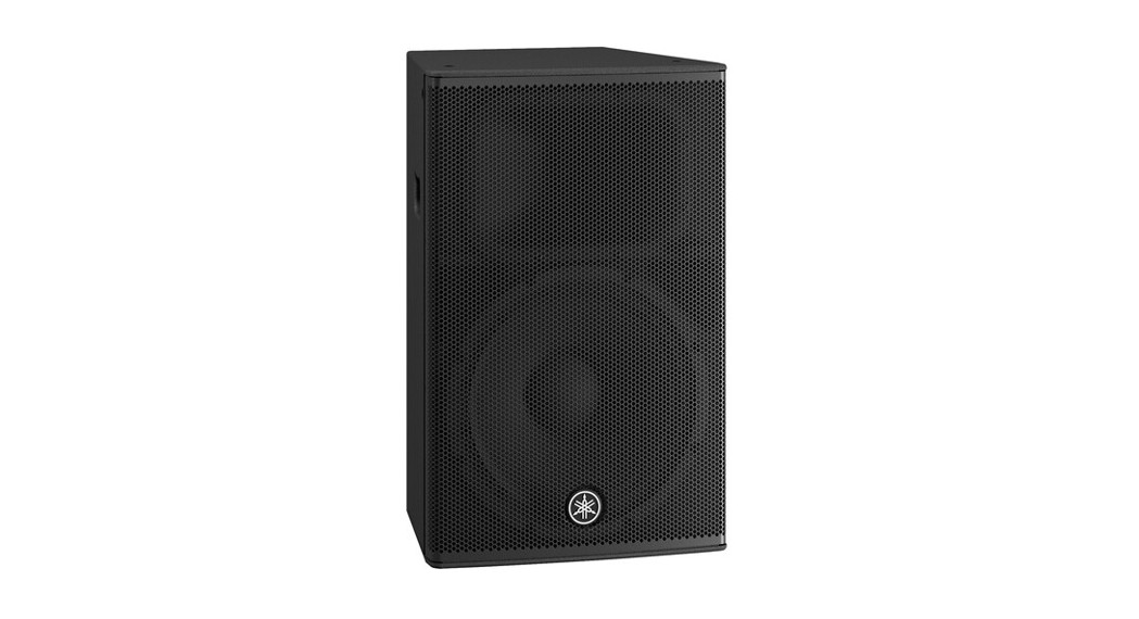
Thank you for purchasing the Yamaha CHR series Loudspeaker. These products are designed for live performance, sound reinforcement, and fixed installation sound system applications. This manual explains how to install and configure the connections for installers, constructors, or general users familiar with speakers. Please read this manual thoroughly before you begin using this product in order to get the most out of its various functions. After reading this manual, please keep it available for future reference.
NOTEThe example illustrations used in this manual are taken from the CHR15, if not otherwise specified.
Main Features
- This is a high-quality speaker unit, with smooth directional characteristics, and has built-in ports that reduce wind roar in order to achieve high-resolution sound
- Delivers high sound pressure thanks to the unit’s high input tolerance and exceptional reliability from protection circuitry.
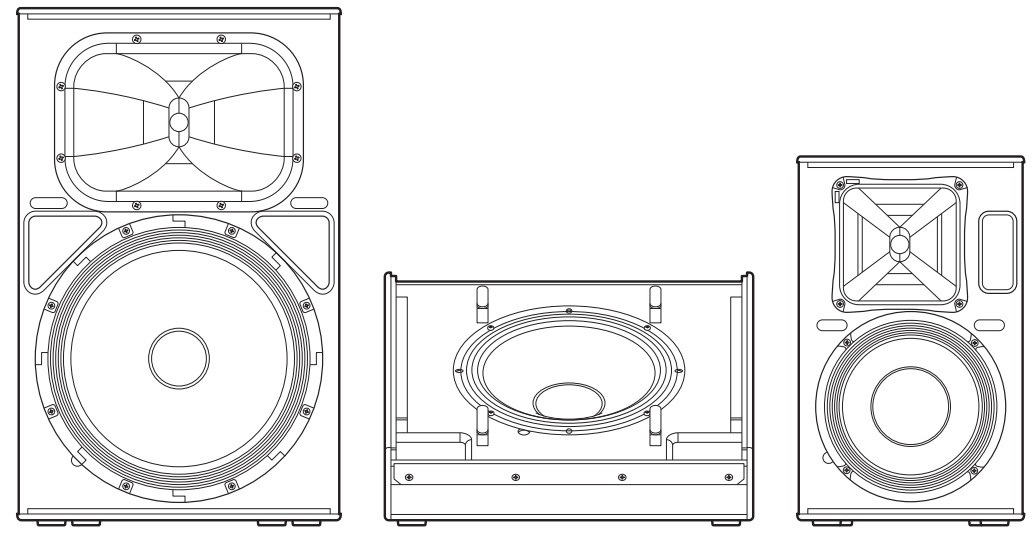
- Features a comprehensive lineup optimized for a variety of applications. The CHR15 is ideal for use as a main speaker delivering powerful sound, while the CHR12M has a sound character optimized for monitoring and is ideal for use as a compact floor The rotatable horn equipped CHR10 is ideal for use as a fixed installation, and can be installed vertically or horizontally with optional brackets.
- The naturally textured wood cabinet of the CHR features a durable coating with high damage resistance to protect the cabinet from scratches and bumps during transport, installations, and removal.
- Equipped with SpeakON Input/output connectors (parallel connection is possible).
- Installable with eyebolt rigging and brackets (CHR15/CHR10).
Included Accessories
- Owner’s manual (this book)
Controls and Connectors
Rear
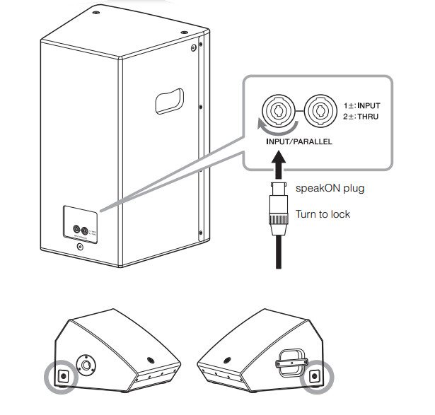
[INPUT/PARALLEL] connectorsThese are speakON connectors (Neutrik NL4) for connection to a power amplifier or a powered mixer using a speaker cable. Use only Neutrik NL4 plugs for connecting speakON connectors.
![]() CAUTIONUse only speaker cables for connecting speakers to the speaker jacks. The use of other types of cables may result in fire.
CAUTIONUse only speaker cables for connecting speakers to the speaker jacks. The use of other types of cables may result in fire.
NOTEFor the CHR12M, [INPUT/PARALLEL] connectors are included on both sides.
Bottom/side
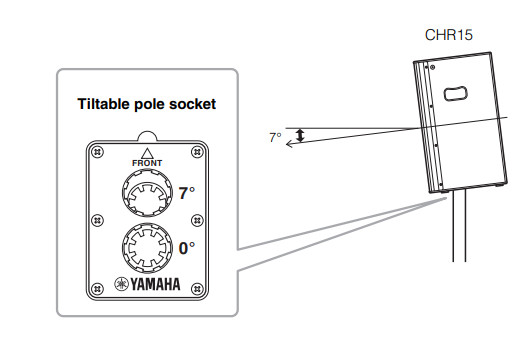
Tiltable pole socket (CHR15)CHR15 has two pole sockets on the bottom. You can choose the angle of the speaker so that it is positioned horizontal to the floor or tilting down toward the floor by 7 degrees. These sockets adapt to commercially available speaker stands and speaker poles of 35 mm diameter.
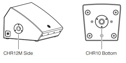
Pole socket (CHR12M, CHR10)CHR12M has a pole socket on the side and CHR10 has one on the bottom.
Connection
Wiring
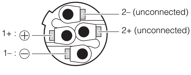
Make sure to wire the plugs as shown below.Neutrik Speakon plug (NL4)
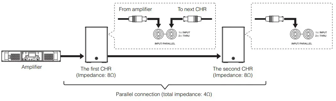
Parallel connection of speakers[INPUT/PARALLEL] connectors are connected inside in parallel. The first CHR receives the signal from an amplifier (such as a power amplifier, a powered mixer, etc.) by one of the [INPUT/PARALLEL] connectors, and routes the signal to the second CHR from the rest of the [INPUT/PARALLEL] connectors.When connecting CHRs in parallel, be sure to check the load impedance the amplifier can drive. The nominal impedance of one CHR is eight ohms and the total impedance of two parallel-connected CHRs is four ohms. In this case, the amplifier must be able to drive less than four-ohm load impedance.
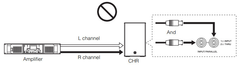
Invalid connectionDo not connect the input from the amplifier to both the [INPUT/PARALLEL] connectors simultaneously. This creates a dangerous short circuit.
Installation Examples
CAUTION
• Before doing any installation or construction work, consult with your Yamaha dealer.• The installation should be checked thoroughly at regular intervals. Some fittings may deteriorate over extended periods of time due to wear and/or corrosion.• When choosing the installation location, suspension wire, and mounting hardware, make sure all are strong enough to support the weight of the speaker.• Make sure to take precautionary measures using wires to prevent the speaker from falling down in the event of an installation failure.• When installing the wire to the wall, install it higher than the wire’s attachment point on the speaker, with as little slack as possible. If the wire is too long, and the speaker happens to fall, the wire may snap as a result of too much strain.• Make sure to use eye bolts according to the standards and safety regulations in your area.
Yamaha cannot be held responsible for damage or injury caused by insufficient strength of the support structure or improper installation.
NOTEWires can be attached to the screw holes for eye bolts and to the screw holes for the U-bracket (CHR10 only) located at the center of the handle. The illustration below is an example of using the U- bracket.

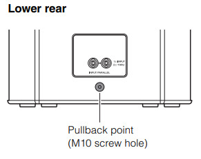
Suspended Installation Using Eye Bolts (CHR15 and CHR10 only)Attach commercially available long eye bolts (30–50 mm in length) to the screw holes located at the top (two locations) and on the lower rear (one location). The screw diameter is M10. Keep in mind that you will need two points at the top to suspend the unit.
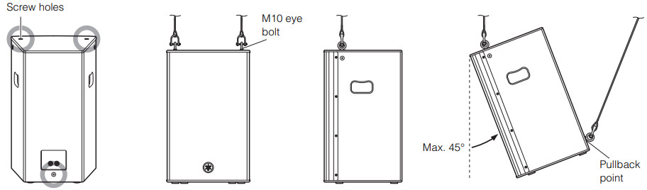
Pullback point
Securing the eye bolts
Remove the flat-head screws tightened at the time of factory shipment, and then insert the eye bolts through the washers when attaching them.

NOTEThe screw holes for eyebolts go through the cabinet wall. When not using eye bolts, tighten the flat-head screws in order to prevent air leaks.
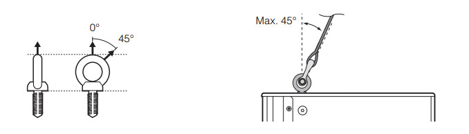
Suspension angle
The strength of an eye bolt differs depending on the suspension angle. Make sure to use eye bolts within a range of 0 to 45 degrees from a right angle (as shown).Correct: Within 45° from a right angle
 Incorrect: Do not suspend the eye bolts as shown in the illustrations below.
 Installation Using a Dedicated U-bracket (CHR10 only)

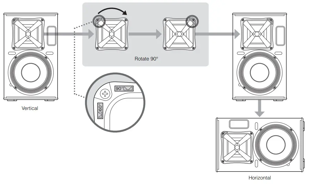
CHR10 can be neatly installed on a ceiling or a wall, either horizontally or vertically, with the separately sold Yamaha UBDXRDHR10 U-bracket. For instructions on installing the U-bracket, refer to the corresponding manual for the UB-DXRDHR10.NOTEThe UB-DXRDHR10 can be used together with separately sold optional brackets, such as the Yamaha BBS251 Baton Bracket.Also, the CHR10 features a rotatable horn (90 degrees). When shipped from the factory, the directivity of CHR10 in a vertical orientation is the setting that makes the sound expand in a horizontal direction, and inhibits or narrows the sound in a vertical direction. We recommend changing the directivity by rotating the horn when you want to install the CHR10 horizontally and broaden the directivity.
Rotatable Horn (CHR10 only)
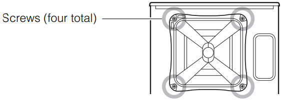
- Using a No. 2 Phillips head screwdriver, remove all fixing screws on the grill, and remove the grille from the speaker.

- Using a No. 2 Phillips head screwdriver, remove all screws installed on the horn and pull the horn out from the speaker.NOTEMake sure not to push the screws too strongly with the Phillips head screwdriver. This may cause the nuts inside the cabinet to fall off.
- Rotate the horn 90 degrees, and re-install the horn to the speaker, reversing the steps above.
Troubleshooting
| Symptom | Possible causes | Possible solution |
| No sound. | The cable is not connected properly. | •Connect the cable all the way in so that it is firmly in place.•Connect to “1+” and “1-” and turn the plug to be locked. |
| Howling sound is produced (feedback). | A microphone is directed toward the speaker. | Aim the speaker away from the area where the microphone picks up sound. |
| The sound is amplified too much. | Lower the volume of input device and locate the microphone more closely to the sound source. | |
| The amplifier shuts down. | The total impedance of the speakers is less than the minimum load impedance of the amplifier.Example:More than two speakers (eight ohms) are connected to a power amplifier, the load impedance of which is six ohms. | Check the minimum load impedance of the power amplifier, and lower the number of speakers connected in parallel not to be less than the impedance. |
| The high-frequency range is attenuated. | The protection circuit is operating in the HF unit. | Refer to “Protective Circuit” in the NOTICE (page 3). |
If any specific problem should persist, however, please contact your Yamaha dealer.
General Specifications
| General | CHR 15 | CHR12M | CHR10 | |
| System Type | 2-way Speaker, Bass-reflex Type | |||
| Frequency Range (-10 dB) | 49 Hz-20 kHz | 61 Hz-20 kHz | 55 Hz-20 kHz | |
| Coverage Angle | H90° x V60° | H90° x V90° | H90° x V60° (Rotatable) | |
| Maximum SPL (Calculated, 1 m) | 125 dB SPL | 123 dB SPL | 122 dB SPL | |
| Crossover Frequency | 2.0 kHz | 1.5 kHz | 2.5 kHz | |
| Nominal Impedance | 80 | 80 | 80 | |
| Power Rating NOISE | 250 W | 250 W | 175 W | |
| (IEC noise) PGM | 500 W | 500 W | 350 W | |
| MAX | 1000 W | 1000 W | 700 W | |
| Sensitivity (1 W, 1 m) | 95 dB SPL | 93 dB SPL | 93 dB SPL | |
| Transducer LF | Diameter | 15″ Cone, 2.5′ Voice Coil | 12′ Cone, 2.5′ Voice Coil | 10′ Cone, 2′ Voice Coil |
| Magnet | Ferrite | |||
| HF | Diameter | 1.4′ Voice Coil,Compression Driver | 1.75″ Voice Coil,Compression Driver, coaxial | 1.4″ Voice Coil,Compression Driver |
| Magnet | Ferrite |
| Enclosure | CHR 15 | CHR12M | CHR10 |
| Material, Color | Plywood, Black, Polyurea coating | ||
| Floor Monitor Angle | – | 57° | – |
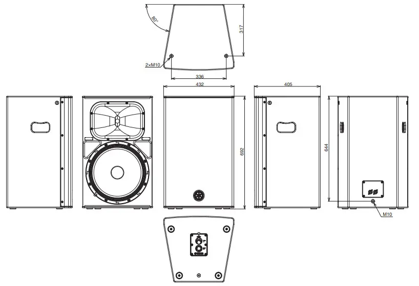
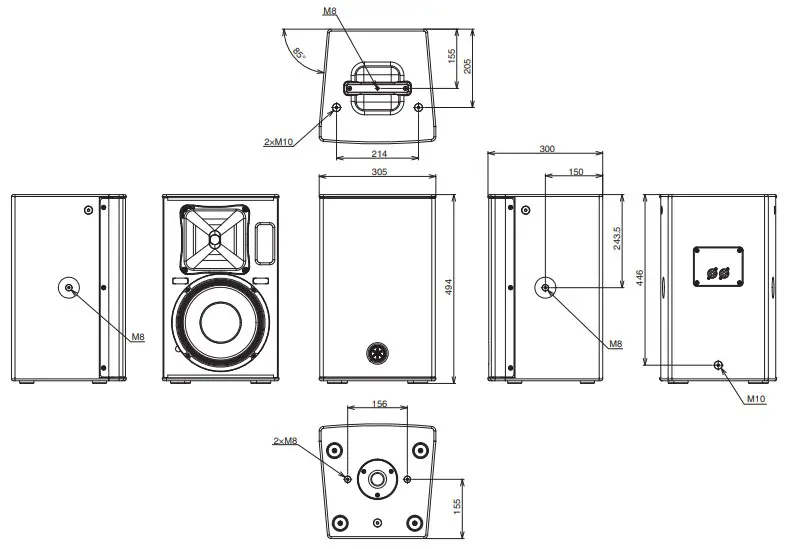
| Dimensions (WxHxD, with rubber feet) | 432 x 692 x 405 mm | 500 x 343 x 454 mm | 305 x 494 x 300 mm |
| Net Weight | 22.0 kg | 15.6 kg | 13.7 kg |
| Handles | Side x 2 | Side x 1 | Top x 1 |
| Pole Socket | 35 mm x 2 (0 and 7 degree) | 35 mm | 35 mm |
| Rigging Points | Top x 2, Rear x 1(Fit for M10 Eyebolts) | Top x 2, Rear x 1(Fit for M10 Eyebolts) | |
| Optional Speaker Bracket | – | – | UB-DXRDHR10 |
| Connectors | SpeakON NL4MP × 2 (parallel connected) |
* The contents of this manual apply to the latest specifications as of the publishing date. To obtain the latest manual, access the Yamaha website then download the manual file.
Dimensions
CHR12M

CHR10
Important Notice: Guarantee Information for customers in European Economic Area (EEA) and SwitzerlandImportant Notice: Guarantee Information for customers in EEA* and SwitzerlandFor detailed guarantee information about this Yamaha product, and Pan-EEA and Switzerland warranty service, please either visit the website address below (The printable file is available on our website) or contact the Yamaha representative office for your country. An EEA: European Economic Area
https://europe.yamaha.com/warranty/
ADDRESS LIST
NORTH AMERICACANADAYamaha Canada Music Ltd.135 Milner Avenue, Toronto, Ontario, M IS 3R1, CanadaTel: +1-416-298-1311The U.S.A.Yamaha Corporation of America6600 Orangethorpe Avenue, Buena Park, CA 90620, U.S.A.Tel: +1-714-522-9011
PA57
Head Office/Manufacturer: Yamaha Corporation 10-1, Nakazawa-Cho, Naka-Ku, Hamamatsu, 430-8650, Japan(For European Union) Importer: Yamaha Music Europe GmbH Siemensstrasse 22-34, 25462 Rellingen, Germany(For United Kingdom) Importer: Yamaha Music Europe GmbH (UK) Sherbourne Drive, Tilbrook, Milton Keynes, MK7 8BL, United Kingdom
Yamaha Pro Audio global website http://www.yamahaproaudio.com/Yamaha Downloads https://download.yamaha.com/Manual Development Group© 2021 Yamaha Corporation Published 03/2021POINT – AOVDK0350
[xyz-ips snippet=”download-snippet”]