

ELECTRONIC DRUM PADPCY100PCY135PCY155
The model number, serial number, power requirements, etc., may be found on or near the nameplate, which is at the bottom of the unit. You should note this serial number in the space provided below and retain this manual as a permanent record of your purchase to aid identification in the event of theft.Model No.Serial No.
 Information for users on collection and disposal of old equipment:
This symbol on the products, packaging, and/or accompanying documents means that used electrical and electronic products should not be mixed with general household waste. For proper treatment, recovery, and recycling of old products, please take them to applicable collection points, in accordance with your national legislation. By disposing of these products correctly, you will help to save valuable resources and prevent any potential negative effects on human health and the environment which could otherwise arise from inappropriate waste handling.For more information about the collection and recycling of old products, please contact your local municipality, your waste disposal service, or the point of sale where you purchased the items.For business users in the European Union: If you wish to discard electrical and electronic equipment, please contact your dealer or supplier for further information. Information on Disposal in other Countries outside the European Union: This symbol is only valid in the European Union. If you wish to discard these items, please contact your local authorities or dealer and ask for the correct method of disposal.
PRECAUTIONS Please read carefully before proceeding.
The purpose of the precautions detailed below is to ensure that this product is used safely without fear either of accidental injury to you or other people or of damage to property. As a means, furthermore, of indicating the severity and immediacy of any risk of injury or damage associated with incorrect operation, these precautions are classified as either WARNING or CAUTION. The instructions presented together with precautions are extremely important in terms of ensuring safety, and therefore, they should be fully observed.After reading this Owner’s Manual, ensure that it is kept in a safe, convenient location for future reference.
 CAUTION: Always follow the basic precautions listed below to avoid the possibility of physical injury to you or others or damage to the instrument or other property. These precautions include, but are not limited to, the following:
- If this product is used with a Rack System or Cymbal Stand, do not place the rack or stand on a sloping, unstable surface, or on steps. The rack or stand may overturn or be damaged, resulting in injury.If this product is used with a Rack System or Cymbal Stand, make sure all bolts are tightened firmly. Also, when adjusting the height or angle, do not suddenly loosen the bolts. Loose bolts may result in the rack overturning or parts dropping, causing injury.
- Please be careful when children are close to or touching the product. Careless movement around the product may result in injury.
- When setting the pads, please pay close attention to the handling and set of cables. Carelessly placed cables may cause the user and others to trip and fall.
- Do not alter the product. Doing so may result in injury or damage/deterioration to the product.
NOTICE
- Do not step on or place heavy objects on the product. It may result in damage.
- Do not use or keep the product in places with extremely high temperatures (places in direct sunlight, close to a heater, in a closed car, etc.) or high humidity (bathroom, outside on a rainy day, etc.). Doing so may result in deformation, discoloration, damage, or deterioration.
- Never leave any materials which are easily color-transferable, such s rubber items, on the drum pad surface. Otherwise, the color of the material may be transferred to the drum pad surface. Be especially careful of this when you store the drum pads.
- When cleaning the product, do not use benzene, thinner, or alcohol as it may result in discoloration or deformation. Please wipe with a soft cloth or a damp cloth that has been wrung out thoroughly. If the product is soiled or sticky, use a neutral detergent on a loth then wipe with a damp cloth that has been wrung out thoroughly to remove any remaining detergent. Also, pay close attention so as not to let the water and detergent come into contact with the cushions used in the product; doing so may result in deterioration.
- Make sure you hold onto the plug, not the cable when connecting or disconnecting the cable. Also, never place any heavy or sharp objects on the cable. Applying excessive force to the cable may result in damage to the cable, such as the wires being severed, etc.
Package Contents
If you have purchased a pad set, please refer to the Assembly Instructions booklet that came with it.
- PCY100: 1. PCY100 pad unit × 1, 2. Stopper × 1, 3. Felt pad × 1, 4. Stereo phone cable × 1, 5. Owner’s Manual (this booklet) × 1
- PCY135: 1. PCY135 pad unit × 1, 2. Stopper × 1, 3. Stereo phone cable × 1, 4. Owner’s Manual (this booklet) × 1
- PCY155: 1. PCY155 pad unit × 1, 2. Stopper × 1, 3. Stereo phone cable × 1, 4. Owner’s Manual (this booklet) × 1
* The edge and cup sections of the PCY100, PCY135, and PCY155 feature independent trigger switches. As a result, it is possible to output different sounds from your tone generator module depending on where you hit the pad unit.
Setting Up
As shown in the diagram, set up your pad unit on an electronic drum rack or a standard cymbal stand (such as a Yamaha CS Series product).
CAUTIONIf the clamp bolt and other fasteners are not sufficiently tightened, your pad unit may fall, possibly causing injury. It is important, therefore, that you mount your pad unit securely on the drum rack or stand. In addition, you should avoid placing your rack or stand on an uneven surface as this may cause it to fall over while being played, again increasing the risk of injury.
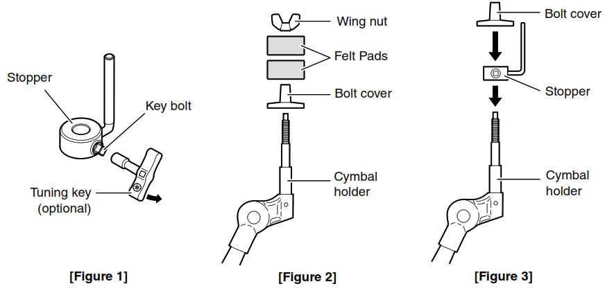
- Using a tuning key (optional), loosen the stopper’s key bolt. (See Figure 1.)
- Remove the wing nut, the two felt pads, and the bolt cover from the cymbal holder. (See Figure 2.)
- Place the stopper on the cymbal holder. (See Figure 3.)NOTE: • If the key bolt was not sufficiently loosened in Step 1 above, it may not be possible to pass the stopper over the cymbal holder’s shaft. In such a case, loosen the key bolt as much as possible without removing it.
- Replace the bolt cover. (See Figure 3.)NOTE: • When assembling the bolt cover, turn until it no longer rotates.

- Secure the stopper in place. With the stopper making full contact with the bottom surface of the Bolsover, tighten the stopper’s key bolt using a tuning key. (See Figure 4.)
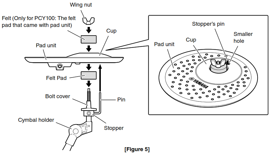
- Place one of the felt pads removed in Step 2 on the cymbal holder. (See Figure 5.)
- Mount the pad unit on the cymbal stand. Lower the pad unit into place with the cymbal holder’s shaft passing through the central hole of the Cup section. When mounted, the stopper’s pin should rest inside the pad unit’s smaller hole. (See Figure 5.)NOTE: If you were to play your pad unit without the stopper’s pin positioned fully inside the smaller hole, it could slip out of the hole as you play.
- For PCY155 and PCY135: Place one of the felt pads removed in Step 2 on the cymbal holder. (See Figure 5.)For PCY100: Place the felt pad that came with your pad unit. The second felt pad removed from the cymbal holder in Step 2 above is not required for assembly of your pad unit. (See Figure 5.)
- Tighten the wing nut to secure the pad unit to the cymbal holder. (See Figure 5.)

Pads & Trigger Input Jacks
The function of the PCY series pads varies according to which trigger input jack on the DTX Series Drum Trigger Module the pad is connected. Refer to the following website for its function in relation to trigger input jacks.
Connecting
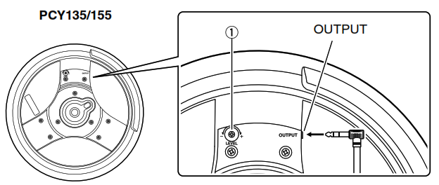
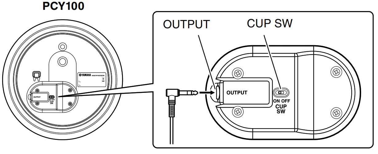
Using the stereo audio cable provided, connect the pad unit’s output to a suitable input jack on a DTX Series Drum Trigger Module. At this time, ensure that the L-shaped end of the cable is plugged into the pad unit’s OUTPUT connector.Adjusting Output Level (PCY135 and PCY155)Using a small screwdriver or a similar tool, you can turn the LEVEL adjustor q on your pad unit to adjust the level of trigger signals that it outputs. Turn clockwise to increase the level and vice-versa. Adjust the trigger signal to best suit the strength of your playing, your desired dynamic range, and the type of DTX Series Drum Trigger Module you are using.
NOTE:
If playing fortissimo (ff) passages with your pad unit connected to a DTX Series Drum Trigger Module, you should set the gain level on the module’s Trigger Setup page such that the input level is indicated as being between 90% and 95%. For more details, refer to the Owner’s Manual for your drum trigger module. Note that an excessively large output level can be the cause of problems such as restricted dynamic range (i.e., very little sensitivity to different playing strengths) and double triggering, where two distinct sounds are produced each time you hit the pad.
NOTICE:
- Applying excessive force to the LEVEL adjustor can result in breakage and should be avoided.
Setting the Cup Switch (PCY100)
Located on the rear of the PCY100, the cup switch (CUP SW) determines whether the pad unit is to be used as a hi-hat or a cymbal. Set to the OFF position for a two-zone hi- hat or to the ON position for a different drum.
Troubleshooting
If you encounter any of the following difficulties when playing your PCY Series pad unit, please take the steps indicated to resolve them before ordering repairs.
No Sound, Volume is Low
- Is the pad connected to the correct input number of the DTX Series Drum Trigger Module using the supplied stereo phone cable? When a pad is connected with a mono phone cable, the voices assigned to the edge and cup sections are not produced.
- If using a PCY135 or PCY155 pad unit, try increasing the LEVEL adjustor setting. (See “Adjusting Output Level (PCY135 and PCY155) ” on page 12 for more details.) Multiple sounds are produced each time the pad is hit (i.e., double triggering).
- If using a PCY135 or PCY155 pad unit, try decreasing the LEVEL adjustor setting. When the level setting is too high, large trigger signals take longer to fade away, and the drum trigger module may interpret them as multiple signals in quick succession. (See “Adjusting Output Level (PCY135 and PCY155) ” on page 12 for more details.)
Also, please refer to the Owner’s Manual that came with your DTX Series Drum Trigger Module for more information regarding the problems described above and any other problems that you may be experiencing. If a solution cannot be found to the problem after consulting the manuals, please contact the dealer from whom you purchased the product.
SpecificationsPCY100 Cymbal Pad (10”)
- Size: 254 (dia.) x 44 mm
- Weight: 0.6 kg
- Sensor System: Trigger sensor (piezo) x 1, two switches (edge, cup)
- Output jack: Standard stereo phone jack
- PCY135 Cymbal Pad (13”)
- Size: 329 (dia.) x 51 mm
- Weight: 1.0 kg
- Sensor System: Trigger sensor (piezo) x 1, two switches (edge, cup)
- Output jack: Standard stereo phone jack
- PCY155 Cymbal Pad (15”)
- Size: 380 (dia.) x 51 mm
- Weight: 1.3 kg
- Sensor System: Trigger sensor (piezo) x 1, two switches (edge, cup)
- Output jack: Standard stereo phone jackSpecifications and descriptions in this Owner’s Manual are for information purposes only. Yamaha Corp. reservesthe right to change or modify products or specifications at any time without prior notice. As specifications, hardware, and optional extras may not be the same in every region, please check with your Yamaha dealer.
Important Notice: Guarantee Information for customers in European Economic Area (EEA) and SwitzerlandImportant Notice: Guarantee Information for customers in EEA* and Switzerland For detailed guarantee information about this Yamaha product, and Pan-EEA’ and Switzerland warranty service, please either visit the website address below (Printable file is available at our website) or contact the Yamaha representative office for your country. • EEA: European Economic Area
Drums Limited Warranty
LIMITED WARRANTY ON YAMAHA DRUMS, HARDWARE, AND ACCESSORY PRODUCTS
Thank you for selecting a YAMAHA product. YAMAHA products are designed and manufactured to provide a high level of defect-free performance. Yamaha Corporation of America (“YAMAHA”) is proud of the experience and craftsmanship that goes into each and every YAMAHA product. YAMAHA sells its products through a network of reputable, specially authorized dealers and is pleased to offer you, the Original Owner, the following Limited Warranty, which applies only to products that have been (1) directly purchased from YAMAHA’s authorized dealers in the fifty states of the USA and District of Columbia (the “Warranted Area”) and (2) used exclusively in the Warranted Area. YAMAHA suggests that you read the Limited Warranty thoroughly, and invites you to contact your authorized YAMAHA dealer or YAMAHA Customer Service if you have any questions. THIS WARRANTY COVERS THE LISTED PRODUCTS AGAINST DEFECTS IN MATERIALS OR WORKMANSHIP.Warranty Term
Duration of Warranty from Date of Purchase by or for the Original Owner
Acoustic Drum Shells, Finish, Drum Hardware, Freestanding Hardware, Pedals, Hardware Accessories 5 Years Electronic Drums Modules, Pads, Accessories, Hardware, Pedals 1 Year
Coverage: YAMAHA will, at its option, repair or replace the product covered by this warranty if it becomes defective, malfunctions, or otherwise fails to conform with this warranty under normal use and service during the term of this warranty, without charge for labor or materials. Repairs may be performed using new or refurbished parts that meet or exceed YAMAHA specifications for new parts. If YAMAHA elects to replace the product, the replacement may be a reconditioned unit. You will be responsible for any installation or removal charges and for any initial shipping charges if the product(s) must be shipped for warranty service. However, YAMAHA will pay the return shipping charges to any destination within the USA if the repairs are covered by the warranty. This warranty does not cover (a) damage, deterioration, or malfunction resulting from accident, negligence, misuse, abuse, improper installation or operation or failure to follow instructions according to the Owner’s Manual for this product; any shipment of the product (claims must be presented to the carrier); repair or attempted repair by anyone other than YAMAHA or an authorized YAMAHA Service Center; (b) any unit which has been altered or on which the serial number has been defaced, modified or removed; (c) normal wear and any periodic maintenance; (d) deterioration due to perspiration, corrosive atmosphere or other external causes such as extremes in temperature or humidity; (e) damages attributable to power line surge or related electrical abnormalities, lightning damage or acts of God; or (f) RFI/EMI (Interference/noise) caused by improper grounding or the improper use of either certified or uncertified equipment, if applicable. Any evidence of alteration, erasing or forgery of proof-of-purchase documents will cause this warranty to be void. This warranty covers only the Original Owner and is not transferable.
In Order to Obtain Warranty Service: Warranty service will only be provided for defective products within the Warranted Area. Contact your local authorized YAMAHA dealer who will advise you of the procedures to be followed. If this is not successful, contact YAMAHA at the address, telephone number, or website shown below. YAMAHA may request that you send the defective product to a local authorized YAMAHA Servicer or authorize the return of the defective product to YAMAHA for repair. If you are uncertain as to whether a dealer has been authorized by YAMAHA, please contact YAMAHA’s Service Department at the number shown below, or check Yamaha’s website at http://usa.yamaha.com. Product(s) shipped for service should be packed securely and must be accompanied by a detailed explanation of the problem(s) requiring service, together with the original or a machine reproduction of the bill of sale or other dated, proof-of-purchase document describing the product, as evidence of warranty coverage. Should any product submitted for warranty service be found ineligible therefore, an estimate of repair cost will be furnished and the repair will be accomplished only if requested by you and upon receipt of payment or acceptable arrangement for payment.
Limitation of Implied Warranties and Exclusion of Damages: ANY IMPLIED WARRANTIES, INCLUDING WARRANTIES OF MERCHANTABILITY AND FITNESS FOR A PARTICULAR PURPOSE, SHALL BE LIMITED IN DURATION TO THE APPLICABLE PERIOD OF TIME SET FORTH ABOVE. YAMAHA SHALL NOT BE RESPONSIBLE FOR INCIDENTAL OR CONSEQUENTIAL DAMAGES OR FOR DAMAGES BASED UPON INCONVENIENCE, LOSS OF USE, DAMAGE TO ANY OTHER EQUIPMENT OR OTHER ITEMS AT THE SITE OF USE OR INTERRUPTION OF PERFORMANCES, OR ANY CONSEQUENCES. YAMAHA’S LIABILITY FOR ANY DEFECTIVE PRODUCT IS LIMITED TO REPAIR OR REPLACEMENT OF THE PRODUCT, AT YAMAHA’S OPTION. SOME STATES DO NOT ALLOW LIMITATIONS ON HOW LONG AN IMPLIED WARRANTY LASTS OR THE EXCLUSION OR LIMITATION OF INCIDENTAL OR CONSEQUENTIAL DAMAGES, SO THE ABOVE LIMITATION OR EXCLUSION MAY NOT APPLY TO YOU. This Warranty gives you specific legal rights, and you may also have other rights which vary from state to state. This is the only express warranty applicable to the product specified herein; Yamaha neither assumes nor authorizes anyone to assume for it any other express warranty.
If you have any questions about service received or if you need assistance in locating an authorized YAMAHA Servicer, please contact:
CUSTOMER SERVICEYamaha Corporation of America6600 Orangethorpe Avenue, Buena Park, California 90620-1373Telephone: 800-854-1569 • http://usa.yamaha.comDo not return any product to the above address without a written Return Authorization issued by YAMAHA.
[xyz-ips snippet=”download-snippet”]