POWERED MIXER
Owner’s ManualThe above warning is located on the rear of the unit.
Explanation of Graphical SymbolsExplication des symboles
The lightning flash with an arrowhead symbol within an equilateral triangle is intended to alert the user to the presence of uninsulated “dangerous voltage” within the product’s enclosure that may be of sufficient magnitude to constitute a risk of electric shock to persons.
The exclamation point within an equilateral triangle is intended to alert the user to the presence of important operating and maintenance (servicing) instructions in the literature accompanying the product.
IMPORTANT SAFETY INSTRUCTIONS
- Read these instructions.
- Keep these instructions.
- Heed all warnings.
- Follow all instructions.
- Do not use this apparatus near water.
- Clean only with dry cloth.
- Do not block any ventilation openings. Install in accordance with the manufacturer’s instructions.
- Do not install near any heat sources such as radiators, heat registers, stoves, or other apparatus (including amplifiers) that produce heat.
- Do not defeat the safety purpose of the polarized or grounding-type plug. A polarized plug has two blades with one wider than the other. A grounding type plug has two blades and a third grounding prong. The wide blade or the third prong are provided for your safety. If the provided plug does not fit into your outlet, consult an electrician for replacement of the obsolete outlet.
- Protect the power cord from being walked on or pinched particularly at plugs, convenience receptacles, and the point where they exit from the apparatus.
- Only use attachments/accessories specified by the manufacturer.
- Use only with the cart, stand, tripod, bracket, or table specified by the manufacturer, or sold with the apparatus. When a cart is used, use caution when moving the cart/apparatus combination to avoid injury from tip-over.

- Unplug this apparatus during lightning storms or when unused for long periods of time.
- Refer all servicing to qualified service personnel. Servicing is required when the apparatus has been damaged in any way, such as power-supply cord or plug is dam-aged, liquid has been spilled or objects have fallen into the apparatus, the apparatus has been exposed to rain or moisture, does not operate normally, or has been dropped.
WARNINGTO REDUCE THE RISK OF FIRE OR ELECTRIC SHOCK, DO NOT EXPOSE THIS APPARATUS TO RAIN OR MOISTURE.
FCC INFORMATION (U.S.A.)
- IMPORTANT NOTICE: DO NOT MODIFY THIS UNIT! This product, when installed as indicated in the instructions contained in this manual, meets FCC requirements. Modifications not expressly approved by Yamaha may void your authority, granted by the FCC, to use the product.
- IMPORTANT: When connecting this product to accessories and/or another product use only high-quality shielded cables. Cable/s supplied with this product MUST be used. Follow all installation instructions. Failure to follow instructions could void your FCC authorization to use this product in the USA.
- NOTE: This product has been tested and found to comply with the requirements listed in FCC Regulations, Part 15 for Class “B” digital devices. Compliance with these requirements provides a reasonable level of assurance that your use of this product in a residential environment will not result in harmful interference with other electronic devices. This equipment generates/ uses radio frequencies and, if not installed and used according to the instructions found in the user’s manual, may cause interference harmful to the operation of other electronic devices.Compliance with FCC regulations does not guarantee that interference will not occur in all installations. If this product is found to be the source of interference, which can be determined by turning the unit “OFF” and “ON”, please try to eliminate the problem by using one of the following measures:Relocate either this product or the device that is being affected by the interference. Utilize power outlets that are on different branch (circuit breaker or fuse) circuits or install AC line filter/s. In the case of radio or TV interference, relocate/reorient the antenna. If the antenna lead-in is 300-ohm ribbon lead, change the lead-in to a co-axial type cable. If these corrective measures do not produce satisfactory results, please contact the local retailer authorized to distribute this type of product.If you can not locate the appropriate retailer, please contact Yamaha Corporation of America, Electronic Service Division, 6600 Orangethorpe Ave, Buena Park, CA90620 The above statements apply ONLY to those products distributed by Yamaha Corporation of America or its subsidiaries.
* This applies only to products distributed by YAMAHA CORPORATION OF AMERICA.
 Information for Users on Collection and Disposal of Old EquipmentThis symbol on the products, packaging, and/or accompanying documents means that used electrical and electronic products should not be mixed with general household waste. For proper treatment, recovery and recycling of old products, please take them to applicable collection points, in accordance with your national legislation and the Directives 2002/96/EC.By disposing of these products correctly, you will help to save valuable resources and prevent any potential negative effects on human health and the environment which could otherwise arise from inappropriate waste handling.For more information about collection and recycling of old products, please contact your local municipality, your waste disposal service or the point of sale where you purchased the items.[For business users in the European Union]If you wish to discard electrical and electronic equipment, please contact your dealer or supplier for further information.[Information on Disposal in other Countries outside the European Union]This symbol is only valid in the European Union. If you wish to discard these items, please contact your local authorities or dealer and ask for the correct method of disposal.The model number, serial number, power requirements, etc., may be found on or near the name plate, which is at the rear of the unit. You should note this serial number in the space provided below and retain this manual as a permanent record of your purchase to aid identifica-tion in the event of theft.
Model No.Serial No.
In Finland: Laite on liitettävä suojamaadoituskoskettimilla varustettuun pistorasiaan.In Norway: Apparatet må tilkoples jordet stikkontakt.In Sweden: Apparaten skall anslutas till jordat uttag.
PRECAUTIONS
PLEASE READ CAREFULLY BEFORE PROCEEDINGPlease keep this manual in a safe place for future reference.WARNINGAlways follow the basic precautions listed below to avoid the possibility of serious injury or even death from electrical shock, short-circuiting, damages, fire or other hazards. These precautions include, but are not limited to, the following:
Power supply/power cord
- Do not place the power cord near heat sources such as heaters or radiators, and do not excessively bend or otherwise damage the cord, place heavy objects on it, or place it in a position where anyone could walk on, trip over, or roll anything over it.
- Only use the voltage specified as correct for the device. The required voltage is printed on the nameplate of the device.
- Use only the supplied power cord/plug. If you intend to use the device in an area other than the one you purchased, the included power cord may not be compatible. Please check with your Yamaha dealer.
- Check the electric plug and each jack periodically, and remove any dirt or dust which may have accumulated. Failure to do so may cause electrical shock, short-circuiting, or fire.
- When setting up the device, make sure that the AC outlet you are using is easily accessible. If some trouble or malfunction occurs, immediately turn off the power switch and disconnect the plug from the outlet. Even when the power switch is turned off, as long as the power cord is not unplugged from the wall AC outlet, the device will not be disconnected from the power source.
- Remove the electric plug from the outlet when the device is not to be used for extended periods of time, or during electrical storms.
- Be sure to connect to an appropriate outlet with a protective grounding connection.
Do not open
- This device contains no user-serviceable parts. Do not open the device or attempt to disassemble the internal parts or modify them in any way. If it should appear to be malfunctioning, discontinue use immediately and have it inspected by qualified Yamaha service personnel.
Water warning
- Do not expose the device to rain, use it near water or in damp or wet conditions, or place on it any containers (such as vases, bottles or glasses) containing liquids that might spill into any openings. If any liquid such as water seeps into the device, turn off the power immediately and unplug the power cord from the AC outlet. Then have the device inspected by qualified Yamaha service personnel.
- Never insert or remove an electric plug with wet hands.
Hearing loss
- Avoid setting all equalizer and level controls to their maximum. Depending on the condition of the connected devices, doing so may result in feedback that can cause hearing loss and damage the speakers.
- Do not use speakers for a long period of time at a high or uncomfortable volume level, since this can cause permanent hearing loss. If you experience any hearing loss or ringing in the ears, consult a physician.
- When turning on the AC power in your audio system, always turn on the device LAST, to avoid hearing loss and speaker damage. When turning the power off, the device should be turned off FIRST for the same reason.
Fire warning
- Do not place any burning items or open flames near the device, since they may cause a fire.
If you notice any abnormality
- If any of the following problems occur, immediately turn off the power switch and disconnect the electric plug from the outlet.– The power cord or plug becomes frayed or damaged.– Unusual smells or smoke are emitted.– Some object has been dropped into the device.– There is a sudden loss of sound during use of the device.– Cracks or other visible damage appear on the device.Then have the device inspected or repaired by qualified Yamaha service personnel.
- If this device should be dropped or damaged, immediately turn off the power switch, disconnect the electric plug from the outlet, and have the device inspected by qualified Yamaha service personnel.
CAUTIONAlways follow the basic precautions listed below to avoid the possibility of physical injury to you or others, or damage to the device or other property. These precautions include, but are not limited to, the following:
Power supply/power cord
- When removing the electric plug from the device or an outlet, always hold the plug itself and not the cord. Pulling by the cord can damage it.
Location
- Do not place the device in an unstable position where it might accidentally fall over and cause injuries.
- Do not block the vents. This device has ventilation holes at the sides to prevent the internal temperature from becoming too high. In particular, do not place the device on its side or upside down. Inadequate ventilation can result in overheating, possibly causing damage to the device(s), or even fire.
- When using the device:– Do not cover it with any cloth.– Do not install it on a carpet or rug.– Do not use the device in a confined, poorly-ventilated location.Inadequate ventilation can result in overheating, possibly causing damage to the device(s), or even fire. If this device is to be used in a small space other than an EIAstandard rack, make sure that there is adequate space around the device: at least 30 cm above, 30 cm at the sides and 30 cm behind.
- Do not place the device in a location where it may come into contact with corrosive gases or salt air. Doing so may result in malfunction.
- Before moving the device, remove all connected cables.
- If the device is mounted in an EIA standard rack, carefully read the section “Precautions for Rack Mounting” on page 24. Inadequate ventilation can result in overheating, possibly causing damage to the device(s), malfunction, or even fire.
Connections
- Do not use speaker cables with a metal-housing connector. Doing so may result in electrical shock due to differences in voltage. Use speaker cables with a nonmetal-housing connector, or with an insulated-housing connector.
- Before connecting the device to other devices, turn off the power for all devices. Also, before turning the power of all devices on or off, make sure that all volume levels are set to the minimum. Failing to do so may result in electric shock or equipment damage.
- Use only speaker cables for connecting speakers to the speaker jacks. Use of other types of cables may result in fire.
Maintenance
- Remove the power plug from the AC outlet when cleaning the device.
Handling caution
- Avoid inserting or dropping foreign objects (paper, plastic, metal, etc.) into any gaps or openings on the device (vents, panel, etc.). If this happens, immediately turn off the power, unplug the power cord from the AC outlet, and have the device inspected by qualified Yamaha service personnel.
- Do not rest your weight on the device or place heavy objects on it. Avoid applying excessive force to the buttons, switches or connectors to prevent injuries.
Yamaha cannot be held responsible for damage caused by improper use or modifications to the device.
NOTICE
To avoid the possibility of malfunction/ damage to the product, damage to data, or damage to other property, follow the notices below.
■ Handling and maintenance
- Do not use the device in the vicinity of a TV, radio, AV equipment, mobile phone, or other electric devices. Otherwise, the device, TV, or radio may generate noise.
- Do not expose the device to excessive dust or vibration, or extreme cold or heat (such as in direct sunlight, near a heater, or in a car during the day), in order to prevent the possibility of panel disfiguration, unstable operation, or damage to the internal components.
- Do not place vinyl, plastic or rubber objects on the device, since this might discolor the panel.
- Place input cables for devices such as microphones, and microphone amplifier circuits with high sensitivity in a location that is far away from the speaker cables. In addition, ensure that the power cord is kept at least 1 cm from the speaker cables. Due to an excessively large current flowing through the speaker cables, it may lead to acoustic noise or electromagnetic interference.
- When cleaning the device, use a dry and soft cloth. Do not use paint thinners, solvents, cleaning fluids, or chemical-impregnated wiping cloths.
- Condensation can occur in the device due to rapid, drastic changes in ambient temperature—when the device is moved from one location to another, or air conditioning is turned on or off, for example. Using the device while condensation is present can cause damage. If there is reason to believe that condensation might have occurred, leave the device for several hours without turning on the power until the condensation has completely dried out.
- Do not use the output of this device for any purpose other than driving loudspeakers.
- Always turn the power off when the device is not in use.
Connectors
- XLR-type connectors are wired as follows (IEC60268 standard): pin 1: ground, pin 2: hot (+), and pin 3: cold (-).
- Use only Neutrik NL4 plugs for connecting speakON connectors.
Information
■ About this manual
- The illustrations and LCD screens as shown in this manual are for instructional purposes only.
- The company names and product names in this manual are the trademarks or registered trademarks of their respective companies.
- Software may be revised and updated without prior notice.
- European modelsPurchaser/User Information specified in EN55103-2:2009. Conforms to Environments: E1, E2, E3 and E4
- Information indicated by “NOTE” provides useful tips.
Thank you and congratulations on your purchase of the Yamaha POWERED MIXER EMX7. This product is a powered mixer for mixing multiple sound sources for live performances by a band or other events. This manual helps users not familiar with mixers to install and configure the connections, and also explains how to use the product. Please read this manual thoroughly to get the most out of the product and ensure long-term, trouble-free use. After reading this manual, please keep it available for future reference.
Main Features
Complete Range of Input Channels
This model is equipped with four mono input channels (channels 1 to 4) and four mono/stereo input channels (channels 5/6 to 11/12).Up to eight microphones can be connected. Line-level devices such as keyboards and CD players can also be connected to each channel. In addition, channel 4 can be used with Hi-Z inputs used to directly connect an instrument such as a guitar or bass guitar.
Compressor
This product is equipped with the popular 1-knob COMP function used in MGP and MG series models. By simply operating a single control, it is possible to get optimal compression for vocals and instruments.
Comprehensive, Professional Effects and Signal ProcessingThis product is equipped with a powerful, comprehensive DSP section that provides the following effects and processors:
- A total of 24 different effects that are in the same league as our famed SPX effect processor series used by professionals. (See page 11.)
- A feedback suppressor, which automatically prevents undesirable feedback noise. (See section
24on page 13.) - A Flex-type graphic equalizer (Flex9GEQ) that allows you to select up to nine bands out of a total of 31 for fine tuning. (See page 19.)
- A speaker processor that allows the connected speakers to be used to their full performance potential. (See page 16.)
High-Efficiency Class-D AmplifierThis model has a built-in high-efficiency power amplifier. Despite its low power consumption, it is capable of high volume output while remaining relatively lightweight. It also has a built-in overload protection function to improve reliability.Rack MountingThis product can be mounted onto a 19-inch rack by using the RK-EMX7 (rack-mount brackets) sold separately.
Accessories (Please check that they are included with your mixer.)
- AC power cord (2.5 m)
- Technical Specifications (English only): Includes general specifications, input/output characteristics, and a block diagram.
- Owner’s Manual (this document)
Quick Start Guide
Getting Sound to the Speakers/Connection Example

Using the Compressor
When the compressor is applied to vocals, it evens out the input level, reducing the level of loud passages and bringing up softer passages. It also makes each sound more distinct, enabling the listener to better understand the performer’s singing.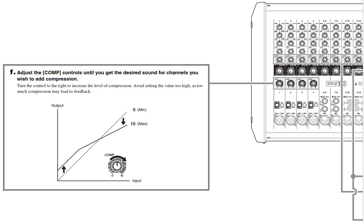
Common Compressor ApplicationsIn addition to vocals, the compressor can be used to enhance the sound of instruments such as guitars, bass guitars, and drums.
Using the Built-in Effects
It is possible to add particular sound effects or effects that simulate the sound of different performance environments, such as concert halls and small clubs.
Controls and Functions
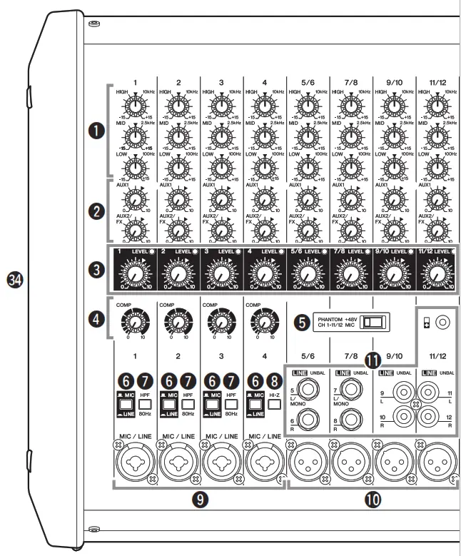
Front Panel
- Equalizer controls [HIGH]/[MID]/[LOW] For adjusting the [HIGH], [MID], and [LOW] audio frequencies. Turning the control to the right amplifies (boosts) the corresponding frequency band while turning to the left attenuates (cuts) the band. Setting the control to the “▼” position produces a flat response in the corresponding band.
- [AUX1] send controls (Channels 1 – 11/12)[AUX2/FX] send controls (Channels 1 – 11/12)For adjusting the levels of each signal sent to the AUX1 and AUX2/ FX (built-in effects) buses from each channel independently. On channels 5/6 to 11/12, the Line L (odd) and Line R (even) input signals are mixed before being sent into the AUX1 and AUX2/FX buses. Adjust the controls so that they are near the “▼” (nominal) position.NOTEThe [AUX1] send control is a PRE setting that is not affected by the [LEVEL] control, and the [AUX2/FX] send control is a POST setting that is affected by the [LEVEL] control.
- [LEVEL] controls (Channels 1 – 11/12)Signal indicators (Channels 1 – 11/12)XLR Phone For adjusting the volume for each channel. When each channel receives an input signal, the signal indicator lights up. To reduce noise, set all [LEVEL] controls on unused channels to the minimum.
- [COMP] controlsFor adjusting the amount of compression applied to the corresponding channel. As the [COMP] control is turned to the right, the threshold, ratio, and output gain are adjusted simultaneously.NOTEAvoid raising the level of the [COMP] control too high, as the higher average output level that results may lead to feedback.
- [PHANTOM +48V] switchTurn this switch on ( ) to supply all the XLR input jacks (channels 1 to 11/12) with DC +48 V phantom power. Turning on the switch supplies power to condenser microphones or a DI (direct injection box). When it is on, the switch lights up.NOTICEFollow the important precautions below, in order to prevent noise and possible damage to external devices and the mixer when you operate this switch.• If you do not need phantom power, or when you connect a device that does not support phantom power, be sure to leave this switch off or connect via the phone (channels 1 to 7/8) / RCA-pin (9/10 and 11/12) / stereo mini (11/12) plugs.• Do not connect or disconnect cables while this switch is on.• Turn @3 AUX1, AUX2, and STEREO MASTER [LEVEL] controls to the minimum setting before operating this switch.
- [ MIC/ LINE] switches (Channels 1 – 4)For channels with low-level input signal devices such as microphones, set the switches to the “ MIC” position. For channels with high-level input signals such as electronic instruments and audio devices, set the switch to the “ LINE” position.
- [HPF] (High Pass Filter) switches (Channels 1 – 3)Turning this switch on () applies a high-pass filter that attenuates frequencies below 80 Hz in the signal by a slope of 12 dB/octave.This function should be kept on when using vocals in order to reduce noise from vibration or wind picked up by the microphone.
- [Hi-Z] switch (Channel 4)Turn this switch on ( ) when you wish to connect instruments with passive pickups such as acoustic-electric guitars or electric bass guitars that do not have internal batteries. It enables such devices to be directly connected to the mixer without the need for a DI (direct injection box). This function affects only the phone jack input.
- [MIC/LINE] input jacks (Channels 1 – 4)For connecting microphones, guitars, electronic musical instruments or audio devices. These are compatible with both XLR and phone plugs.
- [MIC] input jacks (Channels 5/6, 7/8, 9/10, 11/12)These are balanced XLR microphone input jacks.
- [LINE] input jacks (Channels 5/6, 7/8, 9/10, 11/12)For connecting line-level devices such as electronic instruments, acoustic-electric guitars, CD players, and portable audio players. These are compatible with TS phone, RCA-pin, and stereo mini plugs. Using only the [L/MONO] jacks results in the stereo left and right channels outputting the same signal.• Channels 5/6, 7/8: TS phone• Channel 9/10: RCA-pin• Channel 11/12: RCA-pin, stereo miniNOTEIf desired, a single channel’s [LINE] and [MIC] jacks can be used together at the same time. But note that the levels cannot be adjusted independently. The stereo mini jack has priority for channel 11/12 [LINE] input jack.
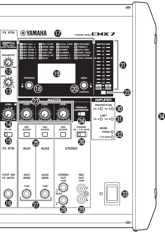
- FX RTN (Effect Return) [PARAMETER] controlFor adjusting parameters (depth, speed, etc.) for the selected effect program. The last value used with each effect program is saved.NOTEWhen you change to a different effect type, the mixer automatically restores the value that was previously used with the newly selected effect (regardless of the current position of the FX RTN [PARAMETER] control).
- FX RTN [AUX1] send controlFor adjusting the level of the signal sent from the built-in effect unit to the AUX1 bus.NOTEThe FX RTN [LEVEL] control does not affect the level of the signal sent to the AUX1 bus.
- FX RTN [LEVEL] controlSignal indicatorFor adjusting the level of the effect sent from the built-in effect unit to the STEREO L/R bus. The signal indicator lights up when a signal is received by the built-in effect unit.
- FX RTN [FX ON] switchFor turning the corresponding built-in effect on or off. It lights up when it is switched on ( ).NOTEIf this switch is on and the footswitch (see “
16FX RTN [FOOT SW] jack”) is used to mute the built-in effect, the switch flashes. - FX RTN [FOOT SW] (Foot Switch) jackFor connecting an unlatched-type footswitch such as the YamahaFC5. It is useful for solo performers since it allows you to mute the effects with your foot.
- Effect program listThis is a convenient on-panel list of the built-in effect programs. For details about these programs, see the “Effect Programs” on page 25.
- [PROGRAM] rotary encoderFor selecting one of the 24 built-in effects. Turn the rotary encoder to select the desired effect, and then press the encoder to enable it.NOTEYou can also select the desired effect by turning the rotary encoder while holding it down.
- DisplayShows the currently used program and settings screens for each function.
- [MENU/CONTROL] rotary encoderFor operating and configuring the SPEAKER PROCESSOR screen or SYSTEM SETUP screen, and setting the graphic equalizer. Turn the rotary encoder to select the desired setting, and then press the encoder to enable it.
- Level meterThis uses LED indicators to show the STEREO L/R, AUX1, and AUX2 signal levels. The “0” (◄) segment corresponds to the nominal output level. The “PEAK” segment on the level meter lights when the output reaches the clipping level.
- Level meter switchThis selects which signal is sent to the level meter. You can use this switch to select the signal from the STEREO L/R, AUX1, or AUX2 buses.
- AUX1 MASTER [LEVEL] controlAUX2 MASTER [LEVEL] controlSTEREO MASTER [LEVEL] controlFor adjusting the level of the signals sent to the AUX1, AUX2, and STEREO L/R.
- [FEEDBACK SUPPRESSOR] switchWhen this switch is on (), it lights up to indicate that feedback is automatically suppressed. (This utilizes a seven-band notch filter.When this switch or the [] (Power) switch is off, the notch filter will be reset.)
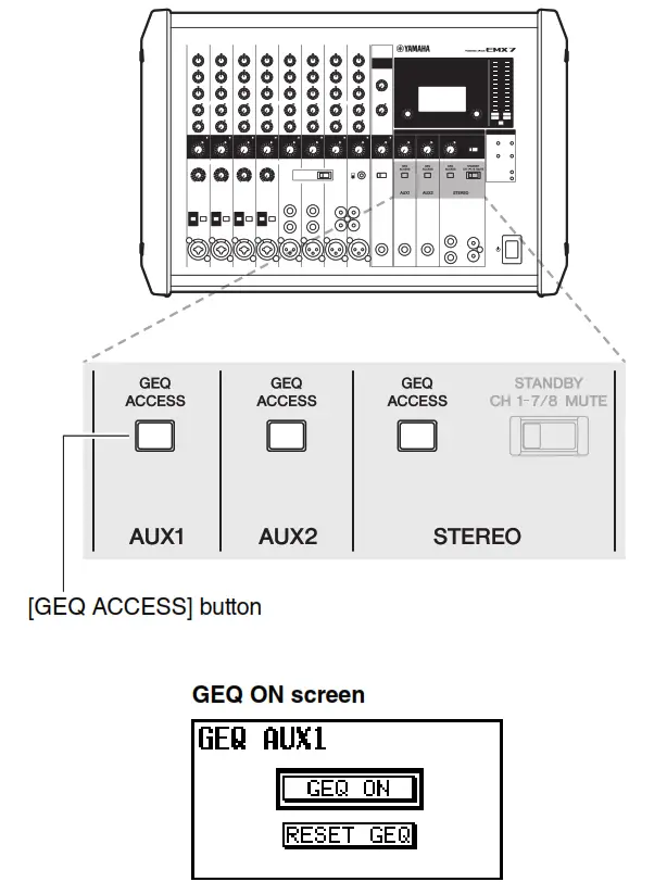
- YAMAHA Powered Mixer EMX7These buttons bring up the graphic equalizer (GEQ) setting screen. Press the [GEQ ACCESS] button corresponding to the channel that you wish to use (AUX1, AUX2 or STEREO). Unlike other switches, these buttons cannot be locked.
- [STANDBY] switchWhen this switch is turned on (), it lights up and all inputs for channels 1 to 7/8 are muted. Please note that channels 9/10 and 11/ 12 are not muted. This is an added convenience for playing background music during gaps in the performance.
- [AUX1 SEND] jack[AUX2 SEND] jackFor connecting to a musician monitoring system, external effect device, and so on. These are impedance balanced TRS phone type output jacks. (See the “Jack and Plug List” on page 26.)
- [STEREO OUT] jacksThese are TRS phone type impedance balanced output jacks that output the mixed stereo signal. The signal level is adjusted by the STEREO MASTER [LEVEL] control before it is output. Using only the [L/MONO] jack lets you obtain a signal composed of the left and right channels mixed together.
- [REC OUT] jacksThese are unbalanced RCA-pin output jacks. They can be used to connect an external recorder. The output signal from these jacks is not affected by the STEREO MASTER [LEVEL] control or graphic equalizer settings. The recording level can be separately adjusted on the recording device.
- AMPLIFIER [PROTECTION] indicatorsLights up to indicate amplifier protection is operating. The “CH A” indicator is for the signal sent to the [SPEAKERS A] jack. The “CH B” indicator is for the signal sent to the [SPEAKERS B] jack.
- AMPLIFIER [LIMIT] indicatorsThese light up when the DSP amplifier protection limiter is operating.The “CH A” indicator is for the signal sent to the [SPEAKERS A] jack. The “CH B” indicator is for the signal sent to the [SPEAKERS B] jack.NOTICEIf used at a very high volume such that the indicators flash continuously, the internal power amplifier section will be excessively overloaded and may malfunction. Reduce the output level with the AUX1 and STEREO MASTER [LEVEL] controls so that the indicators flash only briefly on the highest transient peaks.
- AMPLIFIER [MODE] indicatorsThese indicate whether “STEREO” or “L+R/AUX1” mode is currently selected. For more information about selecting the amplifier mode, see page 17.
- [] (Power) switchFor turning the power ON () or OFF ().
WARNINGPlease note that trace current can continue to flow even when the [
] (Power) switch is in the OFF position. If you do not plan to use the mixer for an extended period of time, be sure to unplug the power cord from the wall outlet.NOTICERapidly turning the [] (Power) switch on and off in succession may cause it to malfunction. After turning the mixer OFF, wait for about 10 seconds before turning it ON again. - VentsThere are vents located on both sides of the mixer, and a cooling fan is installed on the exhaust side. Do not block the vents on either side when using the mixer.

Rear Panel

35. [SPEAKERS A/B] jacksUse commercially available speaker cables to connect the speakers. These jacks can be used with both TS phone and speakON plugs. When connecting a speakON plug, insert it and turn until itlocks in place. The amplifier mode selection determines the outputsignal. For more information about selecting the amplifier mode, see page 17.
| Amplifier Mode Selection | [SPEAKERS A] Jack | [SPEAKERS B] Jack |
| STEREO | STEREO L signal | STEREO R signal |
| L+R/AUX1 | L+R signal | AUX1 signal |
36. [AC IN] jackFor connecting the included power cord here. First, connect the power cord to the mixer, and then plug it into an outlet.NOTICEDo not bundle or tie the power cord and speaker cables during use. Due to the large current flowing through the speaker cables, it may lead to acoustic noise or electromagnetic interference.37. [USB] terminalThis is used only for performing maintenance. It is not used during normal operation.
Screen Procedures
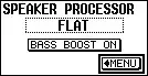
Speaker Processor
The speaker processor function allows you to set a program that selects an appropriate sound quality to match the particular speakers that are connected. It also includes a bass boost function that can be enabled to significantly bring out those lower frequencies.
Selecting the Speaker Processor Program
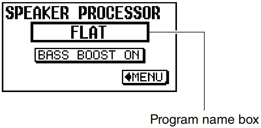
- Call up the SPEAKER PROCESSOR screen. (For more information about the screen procedures, see page 15.)SPEAKER PROCESSOR screen
- Turn the [MENU/CONTROL] rotary encoder until the cursor highlights the program name box.NOTEThe default program name box is FLAT (OFF).
- Press the [MENU/CONTROL] rotary encoder to bring up the program list.NOTE• The program list is automatically closed if no operation is detected for an extended period of time.• The program list includes the names of common Yamaha speakers, etc.
- Turn the [MENU/CONTROL] rotary encoder to select the desired program. Press it to confirm your selection.NOTE• When using a model of speaker that is not included in the program list, select FLAT, or any other setting that satisfies your sound quality requirements.• To return to the HOME screen, operate the [PROGRAM] rotary encoder.
 NOTEThe default program name box is FLAT (OFF).
Turning the Bass Boost Function ON/OFF
- Call up the SPEAKER PROCESSOR screen.(For more information about the screen procedures, see page 15.)SPEAKER PROCESSOR screen
- Turn the [MENU/CONTROL] rotary encoder until the cursor highlights the BASS BOOST ON button.
- Press the [MENU/CONTROL] rotary encoder to turn the bass boost function on or off.
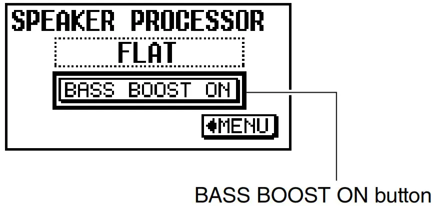

NOTETo return to the HOME screen, operate the [PROGRAM] rotary encoder.
System Setup
Selecting the Amplifier Mode
There are two amplifier modes:• STEREO:When using the SPEAKERS A/B channel for L/R stereo. Provides common 2-channel stereo output.• L+R/AUX1:When using the SPEAKERS A channel for L+R mono, and the SPEAKERS B channel for AUX1. The L+R signal is sent to the main speaker and the AUX1 signal is sent to the monitor speaker for the performers.
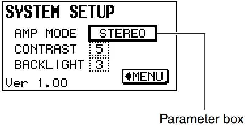
- Call up the SYSTEM SETUP screen. (For more information about the screen procedures, see page 15.)
CAUTIONWhen selecting the amplifier mode, set the AUX1 and STEREO MASTER [LEVEL] controls to “0.” This prevents excessive output from the [SPEAKERS A/B] jacks when switching the amplifier mode.SYSTEM SETUP screen
- Turn the [MENU/CONTROL] rotary encoder until the cursor highlights the AMP MODE parameter box.
- Press the [MENU/CONTROL] rotary encoder so that the parameter box is fully highlighted.
- Turn the [MENU/CONTROL] rotary encoder to change the Amp Mode parameter. You can choose between STEREO and L+R/AUX1 modes.
- Press the [MENU/CONTROL] rotary encoder to confirm your selection.The AMPLIFIER [MODE] indicators on the front panel show the current amplifier mode. (See section
32on page 13.)NOTETo return to the HOME screen, operate the [PROGRAM] rotary encoder.

Setting the LCD Contrast
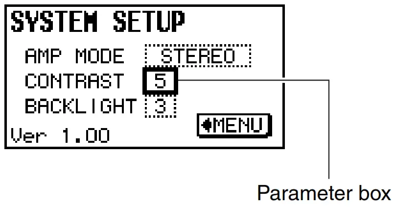
- Call up the SYSTEM SETUP screen. (For more information about the screen procedures, see page 15.)
- Turn the [MENU/CONTROL] rotary encoder until the cursor highlights the CONTRAST parameter box.
- Press the [MENU/CONTROL] rotary encoder so that the parameter box is fully highlighted.
- Turn the [MENU/CONTROL] rotary encoder to set the Contrast parameter. The contrast can be set to any value from 0 to 10, providing 11 different contrast levels.
- Press the [MENU/CONTROL] rotary encoder to confirm your selection.
NOTETo return to the HOME screen, operate the [PROGRAM] rotary encoder.
Setting the LCD Backlight
- Call up the SYSTEM SETUP screen. (For more information about the screen procedures, see page 15.)SYSTEM SETUP screen
- Turn the [MENU/CONTROL] rotary encoder until the cursor highlights the BACKLIGHT parameter box.
- Press the [MENU/CONTROL] rotary encoder so that the parameter box is fully highlighted.
- Turn the [MENU/CONTROL] rotary encoder to set the Backlight parameter. The brightness can be set to any value from 0 to 3, providing 4 different brightness levels.
- Press the [MENU/CONTROL] rotary encoder to confirm your selection.NOTETo return to the HOME screen, operate the [PROGRAM] rotary encoder.

Graphic Equalizer (GEQ)
The EMX7 is equipped with a Flex9GEQ graphic equalizer. The Flex9GEQ allows you to select up to nine bands out of a total of 31 and adjust the gain.
Setting the Frequency and Gain
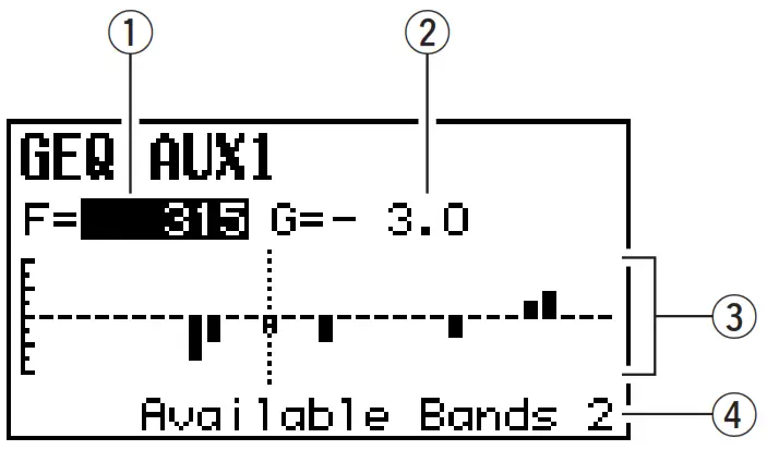
- Call up the GEQ EDIT screen.Press the corresponding AUX1, AUX2 or STEREO [GEQ ACCESS] button for the channel that you wish to apply the graphic equalizer.NOTEIf another screen is being displayed, press the appropriate [GEQ ACCESS] button until the GEQ EDIT screen comes up.(1) FrequencyThis shows the frequency of the currently selected band. (Unit: Hz)(2) GainThis displays the gain value of the currently selected band. (Unit: dB)(3) Graphical representationThis illustrates the current settings.(4) Number of available bandsSince the EMX7 uses a Flex9GEQ graphic equalizer (with a maximum of 9 bands), this shows the number of remaining bands that can be set.
- Select the frequency.When the frequency value is highlighted, turn the [MENU/CONTROL] rotary encoder to select the desired frequency(for adjusting the gain).NOTEWhen the frequency value is not highlighted, press the [MENU/CONTROL] rotary encoder to highlight it, and enable frequency selection.
- Set the gain.Press the [MENU/CONTROL] rotary encoder to highlight the Gain parameter and enable the setting of the gain value for the frequency previously selected in Step 2. Turn the [MENU/CONTROL] rotary encoder to set the gain for the corresponding frequency.
- If necessary, repeat Steps 2 and 3 until the graphic equalizer has been set as needed.NOTE To return to the HOME screen, operate the [PROGRAM] rotary encoder.
 (1) FrequencyThis shows the frequency of the currently selected band. (Unit: Hz)(2) GainThis displays the gain value of the currently selected band. (Unit: dB)(3) Graphical representationThis illustrates the current settings.(4) Number of available bandsSince the EMX7 uses a Flex9GEQ graphic equalizer (with a maximum of 9 bands), this shows the number of remaining bands that can be set.
- Resetting the Gain for the Selected FrequencyPress and hold down the [MENU/CONTROL] rotary encoder for at least two seconds to reset the gain to “0.0” for the selected frequency.NOTEBoth the frequencies and the gain can be reset using the [MENU/CONTROL] rotary encoder.
Turning the Graphic Equalizer (GEQ) ON/OFF
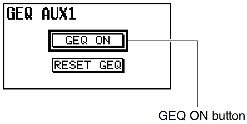
- Call up the GEQ ON screen.Press the corresponding AUX1, AUX2 or STEREO [GEQ ACCESS] button for the channel that you wish to apply the graphic equalizer.NOTEIf another screen is shown, press the appropriate [GEQ ACCESS] button until the GEQ ON screen is called up.
- Turn the [MENU/CONTROL] rotary encoder until the cursor highlights the GEQ ON button.
- Press the [MENU/CONTROL] rotary encoder to turn the graphic equalizer on or off.
NOTETo return to the HOME screen, operate the [PROGRAM] rotary encoder.
- Resetting the Gain for All Frequencies
- When the GEQ ON screen is displayed, turn the [MENU/CONTROL] rotary encoder until the cursor highlights the RESET GEQ button.
- Press the [MENU/CONTROL] rotary encoder to bring up the following confirmation screen.
- Turn the [MENU/CONTROL] rotary encoder until the cursor highlights the OK button. Press the [MENU/CONTROL] rotary encoder to confirm your selection. All gain values will then be reset. (Select the CANCEL button to cancel the reset procedure.)
Troubleshooting
Check the following items before contacting your Yamaha dealer. If the problem remains, contact your nearest Yamaha dealer.
| ■ The power does not come on. | ■ Turn off the Kb] (Power) switch and recheck the connection. Be sure that you are using the included power cord, and that it is correctly connected to the [AC IN] jack and plugged into a working power outlet. If the power still does not come on when pressing the [U] (Power) switch after waiting a few minutes, the mixer may be malfunctioning. If this is the case, contact your nearest Yamaha dealer. |
| ■ The power suddenly turns off. | ■ Check that the vents on the sides of the mixer are not blocked.
■ If the internal temperature of the mixer is excessively high, the overload protection function may have been triggered, causing the power to turn off. Turn off the [U] (Power) switch and restart the mixer after leaving it for a few minutes. |
| ■ The AMPLIFIER [PROTEC- TION] indicators are flashing or constantly on | ■ When flashing, this indicates that the speaker cables connected to the [SPEAKERS] jack for the corresponding channel may be short circuited. Turn off the [U] (Power) switch and inspect the speaker cable for the corresponding channel.
■ When constantly on, this indicates that the output has been muted due to amplifier overheating. Please wait until the amplifier has cooled down to an acceptable level. If it does not reset, turn off the [U] (Power) switch and restart the mixer after leaving it for a few minutes. |
| ■ No sound is heard. | ■ Are external devices (including microphones) and speakers connected correctly?■ Are all the input channel [LEVEL] controls and the AUX1, AUX2, and STEREO MASTER [LEVEL] controls set to appropriate levels?■ For channel 11/12, are both RCA and stereo mini jacks connected at the same time? If both are connected, the stereo mini jack will take priority.■ Check that the speaker cables are not shorted. |
| ■ The sound is low, distorted, or noisy. | ■ Are all the input channel [LEVEL] controls and the AUX1, AUX2, and STEREO MASTER [LEVEL] controls set to appropriate levels?■ Check that the [ |
| ■ The selected effect is not applied. | ■ Check that the [AUX2/FX] send controls on each channel are correctly adjusted.■ Is the FX RTN [FX ON] switch turned on?■ Check that the FX RTN [LEVEL] control is correctly adjusted. |
| ■ The sound from the speakers seems dull, lacking in dynam- ics and power. | ■ Are the equalizer controls [HIGH]/IMIDY[LOW] adjusted appropriately?■ Is the GEQ (graphic equalizer) adjusted appropriately?■ Are the speaker processor and bass boost functions set correctly? |
| ■ Speaking voices are not clear. | ■ Are the equalizer controls [HIGH]/[MID]/[LOW] adjusted appropriately?■ Is the GEQ (graphic equalizer) adjusted appropriately?■ Is the [HPF] switch turned on? |
| ■ How can the monitor output be heard? | ■ Connect a powered speaker (a speaker with an internal amplifier) to the [AUX1 SEND], [AUX2 SEND] jacks. For the [AUX1 SEND] jack and [AUX2 SEND] jack output signals, adjust each channel’s [AUX1] send control, [AUX2/FX] send control, as well as the AUX1 and AUX2 MASTER [LEVEL] controls.■ Set AMP MODE to L+R/AUX1 on the SYSTEM SETUP screen to enable output of the monitor signal (AUX1) from the rear panel [SPEAKERS B] jack. The STEREO UR mixed signal is output from the [SPEAKERS A] jack. |
Appendix
Connecting Speakers
When you wish to connect multiple speakers from the [SPEAKERS A/B] jacks in parallel, keep in mind that the overall impedance does not fall below 4 ohms. When connecting speakers with the same impedance in parallel, the overall impedance value is half with two speakers, one-third with three speakers, and only one-quarter with four speakers.
CAUTION
- When connecting each device, only use appropriately rated cables and plugs. Only use proper speaker cable when connecting speakers.
- Make sure to insert the speaker cables all the way inside until secure. When connecting a speakON plug, insert it all the way inside, then turn until it locks in place.
- Use speaker cables with an insulated-housing connector.
■ 2-channel ConnectionWhen connecting using the following configuration, use speakers with impedance from 4 ohms to 8 ohms. ■2-channel Parallel ConnectionWhen connecting speakers in parallel configuration, use speakers with impedance from 8 ohms to 16 ohms.
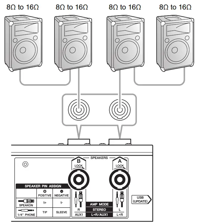
Vertical/Horizontal Orientation and Installation
The mixer orientation can be changed for ease in operation and for adapting to different installation needs.
■ Vertical OrientationThis is convenient when operating the mixer on a tabletop.
■ Horizontal OrientationThis is convenient when operating from a seated position with the mixer placed on the floor.CAUTIONDo not push too forcefully when tilting the mixer. Excess force may cause the mixer to topple or turn, potentially resulting in equipment damage or in injury to bystanders.
■ InstallationThis mixer has vents located on the sides. Please install it so that these vents are well clear of walls or other objects.
Rack Mounting
To prepare the mixer for rack mounting, use the RK-EMX7 (rack-mount brackets) sold separately. This mixer requires 7U* of rack-mount space.* 7U is approximately 312 mm.CAUTIONThis mixer is heavy, and should be lifted by two people when mounting onto a rack.
■ Precautions for Rack MountingThis mixer is rated for operation at ambient temperatures ranging from 0 to 40 degrees Celsius. If you install this mixer along with other devices in a poorly ventilated EIA standard rack, the ambient temperature inside the rack may rise, resulting in inefficient performance. Be sure to rack-mount according to the following conditions so the mixer does not overheat.
- When mounting the mixer in a rack with devices such as power amplifiers that generate a significant amount of heat, leave more than 1U of space between it and other devices. Also, either leave the open spaces uncovered or install appropriate ventilating panels to minimize the possibility of heat buildup.
- To ensure sufficient airflow, leave the rear of the rack open. If you have installed a fan kit in the rack, there may be cases in which closing the rear of the rack will produce a greater cooling effect. Refer to the rack and/or fan kit manual for more details.
■ Assembly of the Rack-mount Brackets1. Use a screwdriver to loosen and remove the 12 screws on the mixer side pads.NOTICE
- During installing the rack-mount brackets, take care to ensure that the screws do not damage surfaces such as table tops. Place a soft cloth under the mixer for protection.
- Use six of the screws you removed in Step 1 to securely install the RK-EMX7 separately sold (rack-mount brackets) onto the mixer.NOTICEBe sure to use the same screws removed from the mixer in Step 1. Using other screws may cause damage.
- Carefully store the remaining six screws that are not used in Step 2 so they are not lost. Once the rack-mount brackets are installed there will be a total of eight empty screw holes on the both sides of the mixer.NOTESeparate screws for actually mounting the mixer in a rack are not included with the mixer.
- If you wish to remove the rack-mount brackets and reinstall the side pads, ensure that they are installed on the correct sides of the mixer. The inside surface of the side pads are marked as “L” (Left) or “R” (Right).
Effect Programs
| No. | Program | Parameter | Description |
| 1 | REV HALL 1 | Reverb Time | Reverb simulating a large space such as a concert hall. |
| 2 | REV HALL 2 | Reverb Time | |
| 3 | REV ROOM 1 | Reverb Time | Reverb simulating the acoustics of a small space (room). |
| 4 | REV ROOM 2 | Reverb Time | |
| 5 | REV STAGE 1 | Reverb Time | Reverb simulating a large stage. |
| 6 | REV STAGE 2 | Reverb Time | |
| 7 | REV PLATE | Reverb Time | Simulation of a metal-plate reverb unit, producing a more hard-edged reverberation. |
| 8 | DRUM AMB | Reverb Time | A short reverb that is ideal for use with a drum kit. |
| 9 | EARLY REF | Room Size | An effect which isolates only the early reflection components from reverberation, creating a ‘flashier’ effect than conventional reverb. |
| 10 | GATE REV | Room Size | An effect which cuts halfway the tail-end of the reverberation, making a more powerful sound. |
| 11 | SINGLE DLY | Delay Time | An effect which repeats the same sound only once. Shortening the delay time produces a doubling effect. |
| 12 | DELAY | Delay Time | Feedback delay adding multiple delayed signals. |
| 13 | VOCAL ECHO | Delay Time | Echo designed for conventional vocals. |
| 14 | KARAOKE | Delay Time | Echo designed for karaoke (sing-along) applications. |
| 15 | PHASER | LFO* Freq | Cyclically changes the phase to add modulation to the sound. |
| 16 | FLANGER | LFO* Freq | Adds modulation to the sound, producing an effect similar to the rise and fall sound of a jet engine. |
| 17 | CHORUS 1 | LFO* Freq | Creates a thicker ensemble-like sound by adding the multiple sounds with different delay times. |
| 18 | CHORUS 2 | LFO* Freq | |
| 19 | SYMPHONIC | LFO* Depth | Multiplies the sound for thicker texture. |
| 20 | TREMOLO | LFO* Freq | An effect which cyclically modulates the volume. |
| 21 | AUTO WAH | LFO* Freq | A wah-wah effect with cyclical filter modulation. The FX RTN [PARAMETER] control adjusts the speed of the LFO* that modulates the „wah„ filter. |
| 22 | RADIO VOICE | Cutoff Offset | Recreates the lo-fi sound of an AM radio. The FX RTN [PARAMETER] control adjusts the frequency band to be emphasized. |
| 23 | DISTORTION | Drive | Adds a sharp-edged distortion to the sound. |
| 24 | PITCH CHANGE | Pitch | An effect which changes the pitch of the signal. |
Jack and Plug List
| Jack (Input/Output) | Polarity | Configuration |
| MIC/LINE (Balanced)MIC (Balanced) | Pin 1: GroundPin 2: Hot (+)Pin 3: Cold (-) | XLR jack |
| MIC/LINE*1(Balanced) | Tip: Hot (+)Ring: Cold (-)Sleeve: Ground | TRS phone plug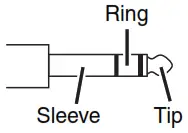 |
| AUX1 SEND*1(Impedance balanced)*2AUX2 SEND *1(Impedance balanced)*2STEREO OUT *1(Impedance balanced)*2 | Tip: Hot (+)Ring: Cold (-)Sleeve: Ground | |
| LINE 5/6, 7/8 (Unbalanced)FOOT SW (Unbalanced) | Tip: SignalSleeve: Ground | TS phone plug |
| LINE 5/6, 7/8(Unbalanced)FOOT SW (Unbalanced) | Tip: PositiveSleeve: Negative | |
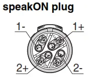
| SPEAKERS A/B | 1+: Positive1-: Negative | speakON plug
|
*1 These jacks also can be connected with TS phone plugs. If you use TS phone plugs, the connection will be unbalanced.*2 Since the hot and cold terminals of impedance balanced output jacks have the same impedance, the balanced connection enables these output jacks to be less affected by induced noise.
Dimensions
General Specifications
| Maximum Output Power (1 kHz) | THD+N <10% 710 W + 710 W (4 0), 500 W + 500 W (8 0)THD+N <1% 600 W + 600 W (4 0), 400 W + 400 W (8 0) | |
| Input Channels | 12 channels (max. 8 MIC/12 LINE, 4 Mono + 4 Stereo) CH4: Hi-Z input supported | |
| Output Channels | SPEAKERS (A, B): 1, AUX1 SEND: 1, AUX2 SEND: 1, STEREO OUT (L, R): 1, REC OUT (L, R): 1 | |
| Bus | Stereo: 1AUX: 2 (Including FX) | |
| Input Channel Function | COMP | Multiple parameters (gain, threshold, ratio) can be adjusted simultaneously with a single control.Threshold: +22 dBu to -8 dBu, Ratio: 1:1 to 4:1, Output level: 0 dB to +7 dBAttack time: approx. 25 ms, Release time: approx. 300 ms |
| Equalizer | HIGH: 10 kHz ±15 dB (Shelving)MID: 2.5 kHz ±15 dB (Peaking)LOW: 100 Hz ±15 dB (Shelving) | |
| Level Meter | 2 x 12 points LED meter (-30, -25, -20, -15, -10, -6, -3, 0, +3, +6, +10, PEAK) | |
| Phantom Power Voltage | +48 V | |
| Built-in Effect | SPX Algorithm | 24 programs |
| FOOT SW | Effect mute on/off | |
| DSP Processing | Feedback suppressor, Graphic equalizer, Speaker processor | |
| Protection | Load Protection: DC-faultAmplifier Protection: Over heat protection, Over current protection, Integral power protection Power Supply Protection: Over heat protection, Over current protection | |
| Power Requirements | AC 100-240 V, 50 Hz/60 Hz | |
| Power Consumption | 45 W (Idle) / 250 W (1/8 Power) | |
| Dimensions when placed vertically (W x H x D) | 465 mm x 308 mm x 325 mm (18.3″ x 12.1″ x 12.8″) | |
| Net Weight | 9.5 kg (20.9 lb) | |
| Optional Accessory | Rack-mount brackets: RK-EMX7, Foot switch: FC5 | |
| Operating Temperature | 0 to +40°C |
For other specifications, see the included “Technical Specifications.”The contents of this manual apply to the latest specifications as of the publishing date. To obtain the latest manual, access the Yamaha website then download the manual file.
Index
Important Notice: Guarantee Information for customers in European Economic Area (EEA) and Switzerland
Important Notice: Guarantee Information for customers in EEA* and Switzerland For detailed guarantee information about this Yamaha product, and Pan-EEA* and Switzerland warranty service, please either visit the website address below (Printable file is available at our website) or contact the Yamaha representative office for your country. * EEA: European Economic Area
https://europe.yamaha.com/warranty
ADDRESS LIST
| NORTH AMERICA CANADAYamaha Canada Music Ltd.135 Milner Avenue, Toronto, Ontario, M1S 3R1, CanadaTel: +1-416-298-1311U.S.A.Yamaha Corporation of America6600 Orangethorpe Avenue, Buena Park, CA 90620, U.S.A.Tel: +1-714-522-9011CENTRAL & SOUTH AMERICAMEXICOYamaha de México, S.A. de C.V.Av. Insurgentes Sur 1647 Piso 9, Col. San JoséInsurgentes, Delegación Benito Juárez, CDMX,C.P. 03900, MéxicoTel: +52-55-5804-0600
BRAZILYamaha Musical do Brasil Ltda.Praça Professor José Lannes, 40, Cjs 21 e 22, BrooklinPaulista Novo CEP 04571-100 – São Paulo – SP, BrazilTel: +55-11-3704-1377 ARGENTINAYamaha Music Latin America, S.A, Sucursal ArgentinaOlga Cossettini 1553, Piso 4 Norte, Madero Este-C1107CEK, Buenos Aires, ArgentinaTel: +54-11-4119-7000 PANAMA AND OTHER LATINAMERICAN/CARIBBEAN REGIONSYamaha Music Latin America, S.A.Edif. Torre Banco General, Piso 7, UrbanizaciónMarbella, Calle 47 y Aquilino de la Guardia,Ciudad de Panamá, República de PanamáTel: +507-269-5311 EUROPETHE UNITED KINGDOM/IRELANDYamaha Music Europe GmbH (UK)Sherbourne Drive, Tilbrook, Milton Keynes,MK7 8BL, U.K.Tel: +44-1908-366700 GERMANYYamaha Music Europe GmbHSiemensstrasse 22-34, 25462 Rellingen, GermanyTel: +49-4101-303-0 SWITZERLAND/LIECHTENSTEINYamaha Music Europe GmbH, Branch Switzerland in ThalwilSeestrasse 18a, 8800 Thalwil, SwitzerlandTel: +41-44-3878080 AUSTRIA/BULGARIA/CZECH REPUBLIC/HUNGARY/ROMANIA/SLOVAKIA/SLOVENIAYamaha Music Europe GmbHBranch AustriaSchleiergasse 20, 1100 Wien, AustriaTel: +43-1-60203900 POLANDYamaha Music Europe GmbHSp.z o.o. Oddział w Polsceul. Wielicka 52, 02-657 Warszawa, PolandTel: +48-22-880-08-88 MALTAOlimpus Music Ltd.Valletta Road, Mosta MST9010, MaltaTel: +356-2133-2093 NETHERLANDS/BELGIUM/LUXEMBOURGYamaha Music Europe Branch BeneluxClarissenhof 5b, 4133 AB Vianen, The NetherlandsTel: +31-347-358040 FRANCEYama ha Mus ic Eu rop e7 rue Ambroise Croizat, Zone d’activités de Pariest,77183 Croissy-Beaubourg, FranceTel: +33-1-6461-4000 ITALYYamaha Music Europe GmbH, Branch ItalyVia Tinelli N.67/69 20855 Gerno di Lesmo (MB), ItalyTel: +39-039-9065-1 SPAIN/PORTUGALYamaha Music Europe GmbH Ibérica, Sucursal enEspañaCtra. de la Coruña km. 17,200, 28231Las Rozas de Madrid, SpainTel: +34-91-639-88-88 GREECEPhilippos Nakas S.A. The Music House19th klm. Leof. Lavriou 190 02 Peania – Attiki, GreeceTel: +30-210-6686168 SWEDEN/FINLAND/ICELANDYamaha Music Europe GmbH Germany filialScandinaviaJA Wettergrensgata 1, 400 43 Göteborg, SwedenTel: +46-31-89-34-00 DENMARKYamaha Music Denmark,Fillial of Yamaha Music Europe GmbH, TysklandGeneratorvej 8C, ST. TH. , 2860 Søborg, DenmarkTel: +45-44-92-49-00 NORWAYYamaha Music Europe GmbH Germany NorwegianBranch Grini Næringspark 1,1332 Østerås, NorwayTel: +47-6716-7800
|
CYPRUSYamaha Music Europe GmbHSiemensstrasse 22-34, 25462 Rellingen, GermanyTel: +49-4101-303-0RUSSIAYamaha Music (Russia) LLC.Room 37, entrance 7, bld. 7, Kievskaya street, Moscow,121059, RussiaTel: +7-495-626-5005OTHER EUROPEAN REGIONSYamaha Music Europe GmbHSiemensstrasse 22-34, 25462 Rellingen, GermanyTel: +49-4101-3030
AFRICAYamaha Music Gulf FZEJAFZA-16, Office 512, P.O.Box 17328, Jebel Ali FZE, Dubai, UAETel: +971-4-801-1500 MIDDLE EAST TURKEYYamaha Music Europe GmbHMerkezi Almanya Türkiye İstanbul ŞubesiMor Sumbul Sokak Varyap Meridian Business 1.BlokNo:1 113-114-115Bati Atasehir Istanbul, TurkeyTel: +90-216-275-7960 OTHER REGIONSYamaha Music Gulf FZEJAFZA-16, Office 512, P.O.Box 17328,Jebel Ali FZE, Dubai, UAETel: +971-4-801-1500 ASIA THE PEOPLE’S REPUBLIC OF CHINAYamaha Music & Electronics (China) Co.,Ltd.2F, Yunhedasha, 1818 Xinzha-lu, Jingan-qu,Shanghai, ChinaTel: +86-400-051-7700 INDIAYamaha Music India Private LimitedP-401, JMD Megapolis, Sector-48, Sohna Road,Gurugram-122018, Haryana, IndiaTel: +91-124-485-3300 INDONESIAPT Yamaha Musik Indonesia DistributorYamaha Music Center Bldg. Jalan Jend. Gatot SubrotoKav. 4, Jakarta 12930, IndonesiaTel: +62-21-520-2577 KOREAYamaha Music Korea Ltd.11F, Prudential Tower, 298, Gangnam-daero,Gangnam-gu, Seoul, 06253, KoreaTel: +82-2-3467-3300 MALAYSIAYamaha Music (Malaysia) Sdn. Bhd.No.8, Jalan Perbandaran, Kelana Jaya, 47301Petaling Jaya, Selangor, MalaysiaTel: +60-3-78030900 SINGAPOREYamaha Music (Asia) Private LimitedBlock 202 Hougang Street 21, #02-00, Singapore 530202, SingaporeTel: +65-6740-9200 TAIWANYamaha Music & Electronics Taiwan Co.,Ltd.2F., No.1, Yuandong Rd., Banqiao Dist.,New Taipei City 22063, Taiwan (R.O.C.)Tel: +886-2-7741-8888 THAILANDSiam Music Yamaha Co., Ltd.3, 4, 15, 16th Fl., Siam Motors Building, 891/1 Rama 1 Road, Wangmai,Pathumwan, Bangkok 10330, ThailandTel: +66-2215-2622 VIETNAMYamaha Music Vietnam Company Limited15th Floor, Nam A Bank Tower, 201-203 Cach MangThang Tam St., Ward 4, Dist.3, Ho Chi Minh City, VietnamTel: +84-8-3818-1122 OTHER ASIAN REGIONShttp://asia.yamaha.com/ OCEANIAAUSTRALIAYamaha Music Australia Pty. Ltd.Level 1, 80 Market Street, South Melbourne,VIC 3205, AustraliaTel: +61-3-9693-5111REGIONS AND TRUST TERRITORIES IN PACIFIC OCEANhttp://asia.yamaha.com/ |
report this adYamaha Pro Audio global website http://www.yamahaproaudio.com/Yamaha Downloads https://download.yamaha.com/
Manual Development Group© 2016 Yamaha CorporationPublished 08/2021POEM-C0VFH2070
[xyz-ips snippet=”download-snippet”]