![]() BOUNDARY MICROPHONERM-TT
BOUNDARY MICROPHONERM-TT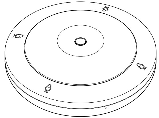 Installation Manual
The model number, serial number, power requirements, etc., may be found on or near the nameplate, which is at the bottom of the unit. You should note this serial number in the space provided below and retain this manual as a permanent record of your purchase to aid identification in the event of theft.Model No.___________Serial No.____________
PRECAUTIONS
PLEASE READ CAREFULLY BEFORE PROCEEDINGPlease keep this manual in a safe place for future reference.Yamaha cannot be held responsible for damage caused by improper use or modifications to the product, or data that is lost or destroyed. WARNINGAlways follow the basic precautions listed below to avoid the possibility of serious injury or even death from electrical shock, short-circuiting, damages, fire or other hazards. These precautions include, but are not limited to, the following:Fire warning
- Do not place any burning items or open flames near the product, since they may cause a fire.
CAUTIONAlways follow the basic precautions listed below to avoid the possibility of physical injury to you or others. These precautions include, but are not limited to, the following:If you notice any abnormality
- If any of the following problems occur, immediately disconnect the LAN cable from the product.– The LAN cable becomes frayed or damaged.– Unusual smells or smoke is emitted.– Some object, or water has been dropped into the product.– Cracks or other visible damage appear on the product.Then have the product inspected or repaired by qualified Yamaha service personnel.
Do not open
- This product contains no user-serviceable parts. Do not attempt to disassemble the internal parts or modify them in any way.Water caution
- Do not expose the product to rain, use it near water or in damp or wet conditions, or place on it any containers (such as vases, bottles, or glasses) containing liquids that might spill into any openings.
Location and connection
- When connecting this product with a PoE injector or a PoE network switch, use a LAN cable that supports PoE. If you connect a cable that does not comply with specifications or connect a flat type or slim type cable, fire or malfunctions might occur.
- Do not damage the LAN cable. Failure to observe this precaution could result in fire, electric shock, or damage to the product.– Do not place heavy objects on the cable.– Do not process the cable in any way.– Do not use staples to fix the cable in place.– Do not apply excessive force to the cable.– Be sure to keep the cable away from anything hot.
- Do not place the product in an unstable position or a location with excessive vibration, where it might accidentally fall and cause injury.
- Keep this product out of reach of children. This product is not suitable for use in locations where children are likely to be present.
- Do not place the product in a location where it may come into contact with corrosive gases or salt air. Doing so may result in malfunction.
- Do not route a LAN cable where someone might trip over them, such as in a location where people pass. Tripping on a cable may cause a person or this product to fall down, resulting in personal injury or damage to the product.
- Before moving the product, remove the connected LAN cable.
- Install in the manner instructed in the manual. Falling may result in injury or damage.
- Confirm that the finished installation is safe and secure. Also, carry out safety inspections periodically. Failure to observe this may cause devices to fall and result in injury.
- Always consult qualified Yamaha service personnel if the product installation requires construction work. Improper installation might cause accidents, injuries, damage or malfunction of this product.
Handling caution
- Do not rest your weight on the product or place heavy objects on it.
NOTICE
To avoid the possibility of malfunction/damage to the product, damage to data, or damage to other property, follow the notices below.Handling and maintenance
- Do not use the product in the vicinity of a TV, radio, or other electric products. Otherwise, the product, TV, or radio may generate noise.
- Do not install the product in a location where magnetic fields are strong. Otherwise, it might cause the product to malfunction.
- Do not expose the product to excessive dust or vibration, or extreme cold or heat, in order to prevent the possibility of disfiguration, unstable operation, or damage to the internal components.
- Do not install in locations where temperature changes are severe. Otherwise, condensation may form on the inside or the surface of the product, causing it to break.
- If there is reason to believe that condensation might have occurred, leave the product for several hours without turning on the power until the condensation has completely dried out, in order to prevent possible damage.
- Do not use a LAN cable that comes into contact with the product case or applies excessive force to the connector.
- Do not touch the interior of a port with your fingers or any metallic object.
- Do not place vinyl, plastic, or rubber objects on the product, since this might cause alteration or discoloration.
- When cleaning the product, use a dry and soft cloth. Do not use paint thinners, solvents, cleaning fluids, or chemical-impregnated wiping cloths, since this might cause alteration or discoloration.
INFORMATION
About functions/data bundled with the product• Warning: Operation of this product in a residential environment could cause radio interference.• This product uses Dante Ultimo. Refer to the Audinate website (English) for details on the open-source licenses for the particular software.https://www.audinate.com/software-licensingRefer to the website below for the licensing terms of the open-source software used in this product.The U.S.A. and Canadahttps://uc.yamaha.com/support/Other countrieshttps://download.yamaha.com/About this manual
- This Manual uses the following signal words for the important information:
 WARNING This content indicates “risk of serious injury or death.”CAUTION This content indicates “risk of injury.” Indicates content that you must observe in order to prevent the product from malfunctioning, being damaged, or operatingNOTICE incorrectly, and to avoid data loss.IMPORTANT Indicates content that you must know in order to operate and use the product correctly.NOTE Indicates information that is related to operation and use. Read this for your reference.
 - The illustrations as shown in this manual are for instructional purposes only.
- The company names and product names in this manual are the trademarks or registered trademarks of their respective companies.
- Yamaha continuously makes improvements and updates to the software included in this product. You can download the latest software from the Yamaha website.
- Unauthorized copying of this document in part or in its entirety is prohibited.
About transfer/disposal
- If you transfer the product to a third party, pass this manual and accessories along with it.
- This product contains recyclable components. When disposing of this product, please contact the appropriate local authorities.
INTRODUCTION
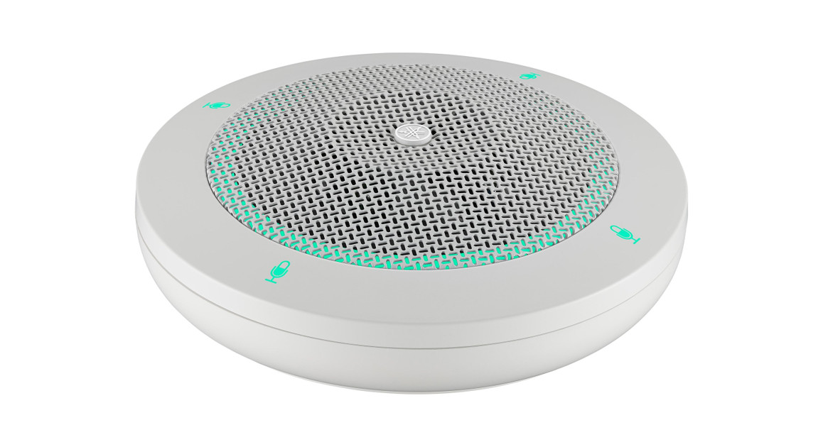
Thank you for purchasing the Yamaha RM-TT boundary microphone. This unit is a PoEpowered tabletop microphone. It is compatible with Dante and can be used in combination with the RM-CR signal processor. Be sure to read this manual before using the unit.Included items
- Tabletop mounting adaptor : 1
- Mounting screws : 3
- Spacers : 3
- Installation Manual (this document) : 1
Reference manuals
- For details on connecting this unit to the RM-CR, refer to the RM-CR Reference Manual.
- For details on the functions and specifications of this unit, refer to the RM-TT Reference Manual.Both publications are available on the Yamaha website.The U.S.A. and Canadahttps://uc.yamaha.com/support/Other countrieshttps://download.yamaha.com/
CONTROLS AND FUNCTIONS
Top panel/side panel
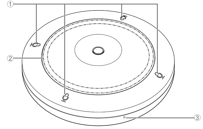
1 ![]() (Mic) buttons/indicatorsTouch a button to turn on/off the microphone. All four buttons/indicators work together.
(Mic) buttons/indicatorsTouch a button to turn on/off the microphone. All four buttons/indicators work together.
| Mic indicator | Microphone status |
| Green | ON |
| Red | OFF |
2 STATUS indicatorIndicates the status of this unit using color and flashing pattern. For details, refer to the RM-TT Reference Manual.3 RESET buttonUse to reset the settings by long-pressing with a fine-tipped object, then releasing it.
| Long press | STATUS indicator | Reset target |
| 4 seconds to less than 8 seconds | Flashes blue twice per second (during long-pressing/resetting) | Network-related settings |
| 8 seconds to less than 12 seconds | Flashes blue three times per second (during long-ressing/resetting) | All settings (automatically restarts after reset) |
Bottom panel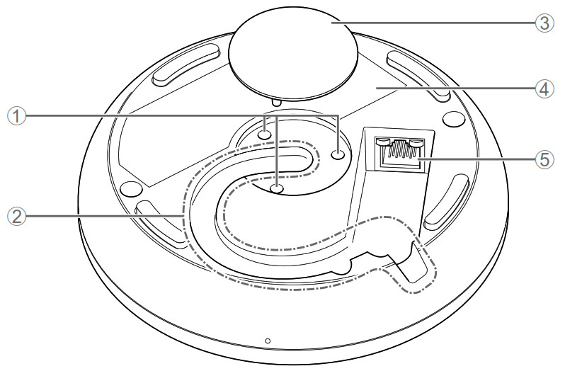
- Mounting screw holesUse for installing the mounting screws.
- Cable slotUse for routing the LAN cable.
- CapRemove when mounting this unit onto a table.
- Product labelProvides information about this unit and marks of conformity with various standards.
- Dante/PoE portThis is an RJ-45 port to which you can connect a LAN cable (CAT5e or higher) via an IEEE802.3af compliant PoE injector or the PoE network switch to a Dante unit. Fordetails on injectors, refer to the RM-TT Reference Manual.NOTICE: Do not connect this product to a public Wi-Fi and/or Internet service directly. Only connect this product to the Internet through a router with strong passwordprotections. Consult your router manufacturer for information on optimum security practices.: Do not connect any device here other than a Dante-compatible device or a device (including a computer) that supports gigabit Ethernet.
INSTALLING ON A TABLE
Be sure to install this unit using the methods described in this manual.Without mounting onto the table1. Plug the LAN cable into the Dante/PoE port.Route through the cable slot as shown below.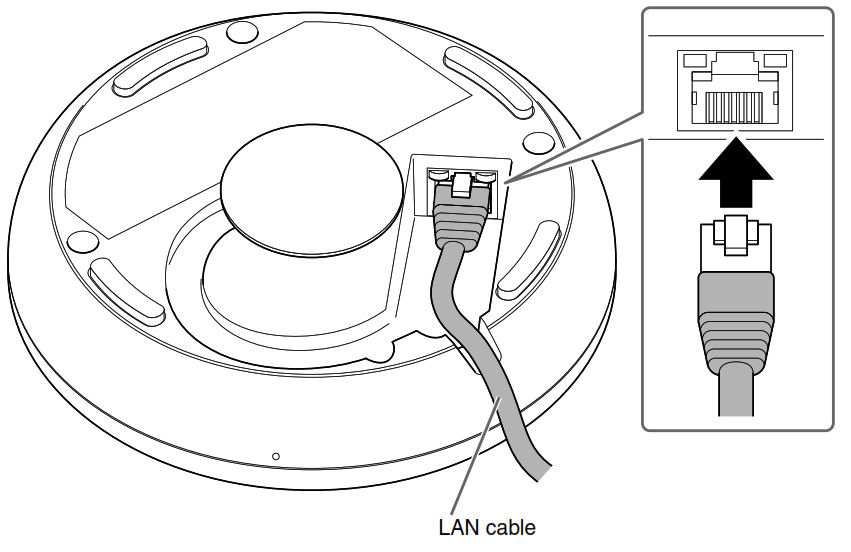
NOTICE: Use STP (Shielded Twisted Pair) cable to prevent electromagnetic interference. : When disconnecting the LAN cable from the Dante/PoE port, wait at least five seconds before reconnecting the cable. Otherwise, damage or malfunctions may result.2. Place this unit on the table.This completes the installation.
When mounting onto the table
Prepare the following.• This unit• Tabletop mounting adaptor (hereafter referred to as adaptor) (included)• Mounting screws × 3 (included)• Spacers × 3 (included)• Commercially available countersunk screws × 3• DrillCAUTION: Be sure to use countersunk screws and a drill (bit) that are appropriate for the material of the table.Using inappropriate hardware and tools may cause injuries or malfunctions or damage to the table.1. Drill a hole in the table.The hole must have a diameter of at least 25 mm. Use an appropriate drill bit.CAUTION: Use appropriate tools when making holes. Using inappropriate tools may cause hand injuries.: Be careful not to get debris or dust in your eyes when making holes.2. Place the adaptor over the hole in the table and secure it with three commercially available countersunk screws.The diameter of the holes for the countersunk screws must be 3.5 mm.The adaptor is inscribed with one LOCK mark and three triangle marks. These four marks indicate the orientation of the Mic buttons/indicators when the unit has been installed. Use these as guides for determining the orientation of the adaptor.

NOTE: There are six holes (including spares) for the countersunk screws. Use any three of them.
3. Remove the cap from the bottom of this unit, and then install three mounting screws through the mounting holes.Place one spacer on each screw.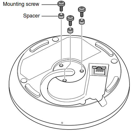
4. Plug the LAN cable into the Dante/PoE port.Route through the cable slot as shown below.
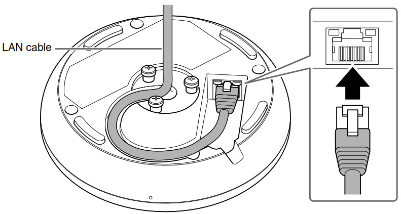
NOTICE: Use STP (Shielded Twisted Pair) cable to prevent electromagnetic interference. : When disconnecting the LAN cable from the Dante/PoE port, wait at least five seconds before reconnecting the cable. Otherwise, damage or malfunctions may result.
5. Pass the LAN cable through the center of the adaptor, and then place this unit on the adaptor.The adaptor is inscribed with a RELEASE mark. Align the notch in the adaptor indicated by that mark with the cable slot in the side of the unit.
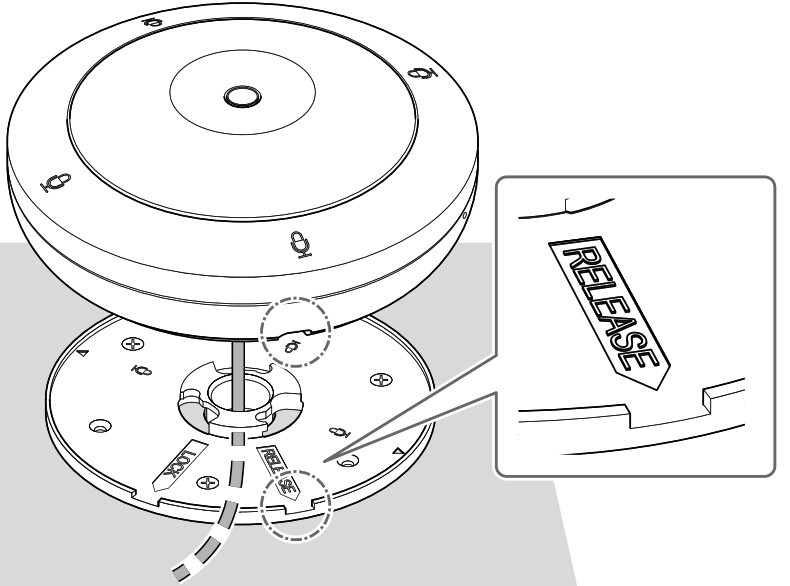
6. Rotate the unit 45° clockwise (as seen from the top).Engaging the mounting screws and adaptor completes the installation.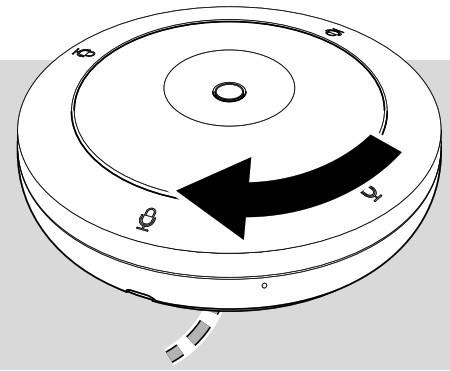
NOTE: To remove the unit, rotate it 45° counterclockwise.
MAIN SPECIFICATIONS
General specifications
| Dimensions | W 140.0 mm x D 140.0 mm x H 40.0 mm (excluding protrusions) | |
| Weight | 310 g | |
| Power requirements | PoE (IEEE802.3af), DC48 V | |
| Maximum power consumption | 4.5 W | |
| In operation | Temperature | 0 °C – 40 °C |
| Humidity | 30% – 90% (no condensation) | |
| Storage | Temperature | -20 °C – 60 °C |
| Humidity | 20% – 90% (no condensation) | |
| Indicators | •Mic•Status•Network port | |
| Maximum device number with RM-CR | a | |
| Accessories | •Tabletop mounting adaptor: 1•Mounting screw : 3•Spacer : 3•Installation Manual (this document) : 1 |
Network specifications
| Dante/PoE port | • Dante audio/Dante control• Remote control• PoE• Cable requirements: CAT5e or higher, STP |
Audio specifications
| Frequency response | 160 Hz – 16 kHz (-10 dB) |
| Sampling rate | 48 kHz |
| Bit depth | 24-bit |
| Latency | 57 [ms] (including signal processing) |
| Audio input/output (Dante) | 1in x2out•Inl: AEC reference signal•Out1: output of beam mix•Out2: output of beam mix (simple processed) |
| The maximum input level of SPL (0 DBS) | 106.8 dB SPL |
| Self-noise | 6.3 dBA SPL |
| SNR(Ref. 94 dB SPL at 1 kHz) | 87.7 dBA |
| Sensitivity | -12.8 dBFS/Pa |
| Dynamic range | 100.5 dBA |
| Signal processing | •Auto voice tracking•Selectable polar pattern: Cardioid, Hypercardioid, Supercardioid, Omnidirectional, Bidirectional, Toroid•AEC, NR, Dereverberation, Auto Mixer, AGC, User PEQ, Output gain |
The contents of this manual apply to the latest specifications as of the publishing date. To obtain the latest manual, access the Yamaha website then download the manual file.
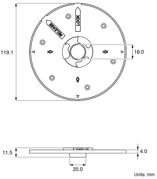
Dimensional diagram
This unit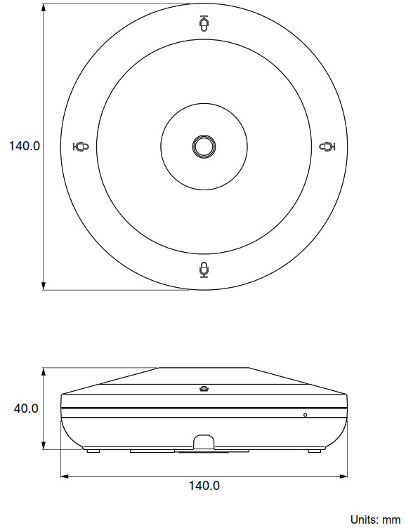
Tabletop mounting adaptor
Information for users on collection and disposal of old equipment:![]() This symbol on the products, packaging, and/or accompanying documents means that used electrical and electronic products should not be mixed with general household waste.For proper treatment, recovery, and recycling of old products, please take them to applicable collection points, in accordance with your national legislation.By disposing of these products correctly, you will help to save valuable resources and prevent any potential negative effects on human health and the environment which could otherwise arise from inappropriate waste handling.For more information about the collection and recycling of old products, please contact your local municipality, your waste disposal service or the point of sale where you purchased the items.For business users in the European Union:If you wish to discard electrical and electronic equipment, please contact your dealer or supplier for further information.Information on Disposal in other Countries outside the European Union:This symbol is only valid in the European Union. If you wish to discard these items, please contact your local authorities or dealer and ask for the correct method of disposal.
This symbol on the products, packaging, and/or accompanying documents means that used electrical and electronic products should not be mixed with general household waste.For proper treatment, recovery, and recycling of old products, please take them to applicable collection points, in accordance with your national legislation.By disposing of these products correctly, you will help to save valuable resources and prevent any potential negative effects on human health and the environment which could otherwise arise from inappropriate waste handling.For more information about the collection and recycling of old products, please contact your local municipality, your waste disposal service or the point of sale where you purchased the items.For business users in the European Union:If you wish to discard electrical and electronic equipment, please contact your dealer or supplier for further information.Information on Disposal in other Countries outside the European Union:This symbol is only valid in the European Union. If you wish to discard these items, please contact your local authorities or dealer and ask for the correct method of disposal.
COMPLIANCE INFORMATION STATEMENT
(Supplierʼs declaration of conformity procedure)Responsible Party: Yamaha Unified Communications, Inc.Address: 144 North Rd, Suite 3250 Sudbury, MA 01776Telephone: 800-326-1088Type of Equipment: Boundary MicrophoneModel Name: RM-TTThis device complies with Part 15 of the FCC Rules.Operation is subject to the following conditions:1) this device may not cause harmful interference, and2) this device must accept any interference received including interference that may cause undesired operation.
FCC INFORMATION (U.S.A.)
- IMPORTANT NOTICE: DO NOT MODIFY THIS UNIT!This product, when installed as indicated in the instructions contained in this manual, meets FCC requirements. Modifications not expressly approved by Yamaha may void your authority, granted by the FCC, to use the product.
- IMPORTANT: When connecting this product to accessories and/or another product use only high-quality shielded cables. Cable/s supplied with this product MUST be used. Follow all installation instructions. Failure to follow instructions could void your FCC authorization to use this product in the USA.
- NOTE: This equipment has been tested and found to comply with the limits for a Class A digital device, pursuant to Part 15 of the FCC rules. These limits are designed to rovide reasonable protection against harmful interference when the equipment is operated in a commercial environment. This equipment generates, uses, and can radiate radio frequency nergy and, if not installed and used in accordance with the instruction manual, may cause harmful interference to radio communications. Operation of this equipment in a residential area is likely to cause harmful interference in which case the user will be required to correct the interference at his own expense.
[xyz-ips snippet=”download-snippet”]