
YDLIDAR X4USER MANUAL
 Doc#:01.13.000003
YDLIDAR X4 DEVELOPMENT KIT
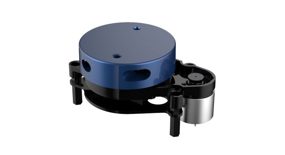
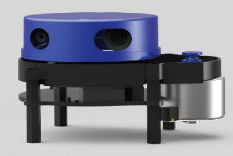
The YDLIDAR X4 (hereafter abbreviated as X4) development kit is designed to facilitate users’ performance evaluation and early development of the X4. By using the X4 development kit and matching evaluation software, point cloud data scanned by X4 to the environment can be observed on the PC or developed on the SDK.
Development Kit
The X4 development kit has the following components:
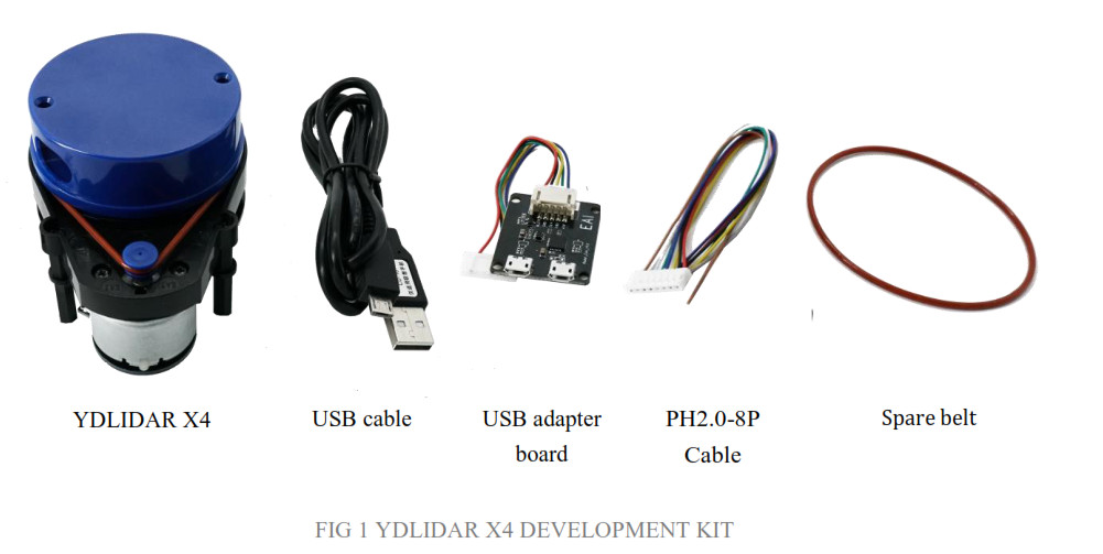
CHART 1 YDLIDAR X4 DEVELOPMENT KIT DESCRIPTION
| Item | Qty | Description |
| X4 Lidar | 1 | Standard version of the X4 Lidar. The X4 has an integrated motor drive for motor control. |
| USB cable | 1 | Use with USB adapter board to connect X4 and PC.It is both a power supply line and a data line. |
| USB adapter board | 1 | This component is used for USB to UART functions, enabling X4 and PC to be quickly interconnected.Also supports the serial port DTR signal to the X4 motor stop control.A MicroUSB Power Interface (PWR) for auxiliary power supply is also provided. |
| PH2.0-8P cable | 1 | This component meets the user’s development needs in a multi-platform environment. |
| Spare belt | 1 | Used as a replacement |
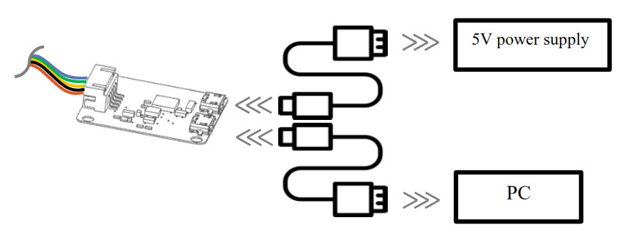
Note: USB adapter board has two MicroUSB interfaces: USB_DATA, USB_PWR.USB_DATA: Data supply multiplex interface. In most cases, just using this interface can meet the power and communication needs.USB_PWR: Auxiliary power interface. The USB interface of some development platforms has a weak current drive capability and auxiliary power can be used.
WINDOWS USAGE GUIDE
Device connection
When evaluating and developing X4 under windows, you need to interconnect X4 and PC. The specific process is as follows: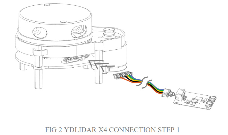
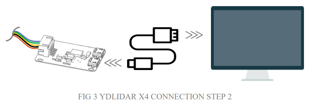
Connect the adapter board and X4 first, and then connect the USB cable to the USB port on the adapter board and the PC. Note that the USB interface’s Micro interface is connected to the USB adapter’s USB_DATA. After the X4 is powered on, it is in idle mode and the motor does not turn. The drive current of the USB interface of some development platforms or PCs is weak, and the X4 needs to access the +5V auxiliary power supply, otherwise, the radar will work abnormally.
 Driver Installation
 Driver Installation
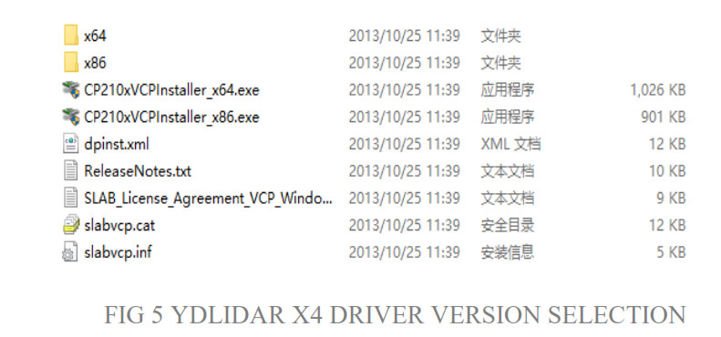
To evaluate and develop the X4 under Windows, you need to install the serial port driver of the USB adapter board. The USB adapter board of this kit adopts a CP2102 chip to realize serial port (UART) to USB signal conversion. Its driver can be downloaded from our official website or downloaded from the official website of Silicon Labs:http://ydlidar.com/http://cn.silabs.com/products/development-tools/software/usb-to-uart-bridge-vcp-driversAfter extracting the driver package, run the CP2102’s Windows driver installation file (exe file under CP210x_VCP_Windows). Please select the 32-bit version (x86) or 64-bit version (x64) installation program according to the version of the windows operating system.
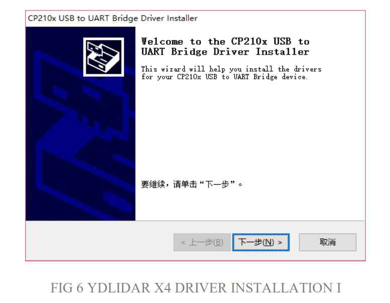
 Double-click the exe file and follow the prompts to install it
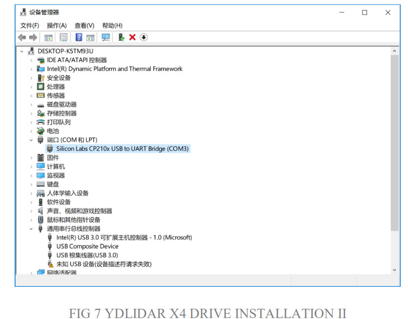
After the installation is complete, you can right-click My Computer and select Properties. Under the System screen, select Device Manager from the left menu to access the device manager. Expand [Port] to see the serial port name corresponding to the identified USB adapter, that is, the driver installation is successful. The following figure shows COM3. (Note that the port must be checked in case of X4 and PC interconnection)
Evaluation software
YDLIDAR provides Point Cloud Viewer, a point cloud data visualization software for X4 real-time scanning. The user can intuitively observe the X4 scan effect picture using this software. YDLIDAR provides X4 real-time point cloud data and real-time scanning frequency, and X4 version information can be read at the same time. And can save the scan data offline to an external file for further analysis.Before using YDLIDAR, make sure that the X4 USB adapter board serial port driver is installed successfully, and check whether the X4 and PC USB ports are successfully interconnected. Run the evaluation software: PointCloudViewer.exe, select the corresponding serial port number and model number.

If the connection is normal, you will see the following screen: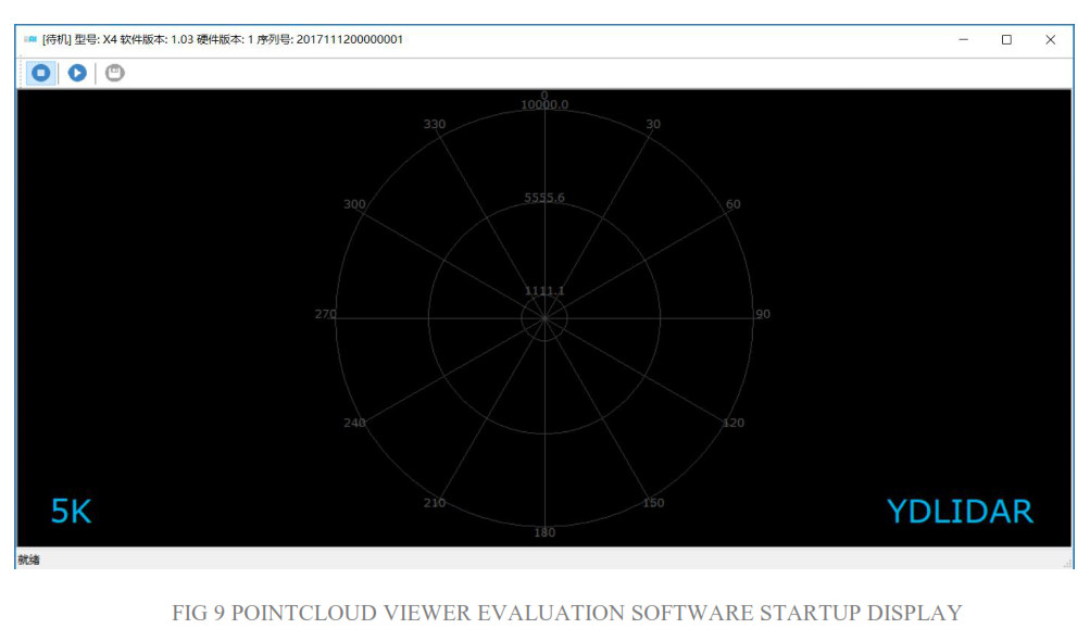
The title bar shows the software/hardware version and serial number information for this lidar.![]() These are menu bars: Available when the icon is blue and unavailable when it is gray.
These are menu bars: Available when the icon is blue and unavailable when it is gray.![]() :Stop scanning: Lidar is in idle mode. In this mode, the lidar’s motor is stopped and is in standby mode.
:Stop scanning: Lidar is in idle mode. In this mode, the lidar’s motor is stopped and is in standby mode.![]() :Start scanning: Lidar will enter scanning mode. After starting the scan, point cloud data can be observed on the software interface.
:Start scanning: Lidar will enter scanning mode. After starting the scan, point cloud data can be observed on the software interface.![]() :Save the scan data acquired by X4 to a file for easy viewing and analysis.Click to start scanning; you can see the point cloud data in the software interface as shown below:
:Save the scan data acquired by X4 to a file for easy viewing and analysis.Click to start scanning; you can see the point cloud data in the software interface as shown below:
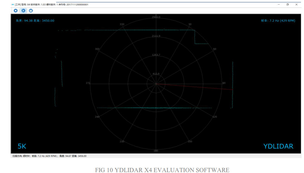
Move the mouse to any sampling point and you can see the distance value and angle of the point in the red text. The scanning frequency of the laser radar can be read from the text on the upper right of the screen.
LINUX ROS OPERATION
Because there are many Linux versions, this article only uses Ubuntu 16.04, Kinetic version ROS asan example.
File description
Download YDLIDAR’s latest ROS driver package at http://www.ydlidar.com/download;
| File | Description |
| f4.launch | Run the file, F4 Lidar starts scanning, no data, no point cloud display |
| f4_view.launch | Run the file, Lidar F4 starts scanning and shows the point cloud |
| g4.launch | Run the file, G4 Lidar starts scanning, no data, no point cloud display |
| g4_view.launch | Run the file, Lidar G4 starts scanning and shows the point cloud |
| x4.launch | Run the file, X4 Lidar starts scanning, no data, no point cloud display |
| x4_view.launch | Run the file, Lidar X4 starts scanning and shows the point cloud |
| Lidar.launch | Run the file, Lidar (G4, F4 and X4) starts scanning, no data, no point cloud display |
| Lidar_view.launch | Run the file, Lidar (G4,F4 and X4) starts scanning and shows the point cloud |
Note 1: need to select the correct file to run, for example, X4 cannot run f4_view.launch, you can run x4_view.launch and Lidar_view.launch;Note 2: To run Lidar_view.launch and Lidar. launch, you need to confirm that the Lidar. launch configurationinformation is correct. See the configuration instructions for details.
| File | Description |
| port | The lidar serial number defaults to ydlidar. When connecting multiple radars, the serial port will have a duplicate name error. |
| baudrate | Serial port baud rate: G4 default is: 230400 |
| frame_id | Lidar coordinate system: default is laser_frame |
| angle_fixed | Lidar Angle Correction Settings: Default is true |
| intensities | Lidar signal strength settings, G4, X4, F4 fixed to false |
| angle_min | Lidar scan start angle soft setting: direction defaults to clockwise |
| angle_max | Lidar scan start angle soft setting: direction defaults to counterclockwise |
| range_min | Lidar minimum range: default is 0.08 |
| range_max | Lidar maximum range: default is 16.0 |
| ignore_array | Lidar scan angle hard setting: Default is not set. The system uses soft settings by default |
In general, X4 can be configured as below: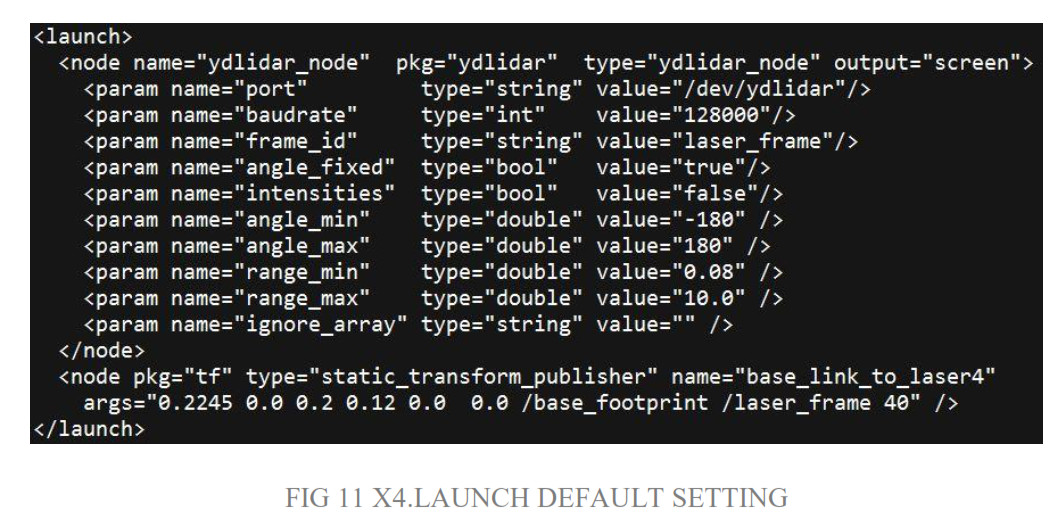
Device connection
Under Linux, the X4 and PC interconnect processes are consistent with those under Windows. See Device Connection under Window.
ROS Driver Installation
Before doing the following, make sure that the Kinetic version ROS environment is installed correctly.Specific steps are as follows:(1)Use the command to create the ydlidar_ws workspace and copy the ROS driver package ydlidar in the X4 package to the ydlidar_ws/src directory. Switch to the ydlidar_ws workspace and compile again.
| $ mkdir -p ~/ydlidar_ws/src$ cd ~/ydlidar_ws$ catkin_make |
(2After the compilation is complete, add the ydlidar environment variable to the ~/.bashrc file and make it effective.
| $ echo “source ~/ydlidar_ws/devel/setup.bash” >> ~/.bashrc$ source ~/.bashrc |
(3 Add a device alias /dev/ydlidar to the X4 serial port.
| $ cd ~/ydlidar_ws/src/ydlidar/startup$ sudo chmod +x initenv.sh$ sudo sh initenv.sh |
RVIZ installation
(1)Online installation
| $ sudo apt-get install python-serial ros-kinetic-serial g++ vim \ ros-kinetic-turtle bot-rviz-launchers |
(2 If there is a problem with the installation, update the source cache and reinstall it.
| $ sudo apt-get update |
RVIZ Check the scan results
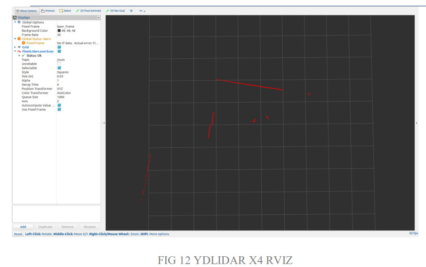
Run the launch file and open rviz to view the X4 scan results, as shown in the following figure:
| $ roslaunch ydlidar x4_view.launch |
Modify the scan angle problem
The scanning data seen by running the launch file is displayed by default with 360-degree data. To modify the display range, you need to modify the configuration parameters in the launch file. The specific operation is as follows:
- Go to x4.launch’s directory and use vim to edit x4.launch. The contents are as shown in the figure:
| $ roscd ydlidar/launch$ vim x4.launch |
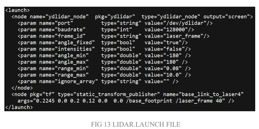
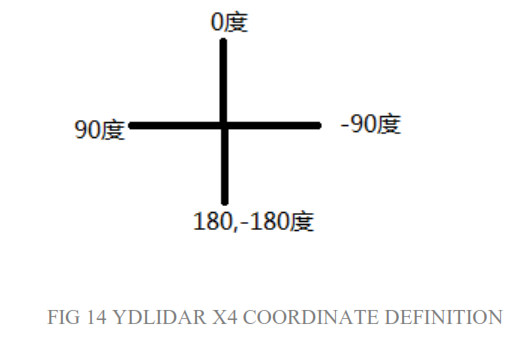
2. The X4 lidar coordinates follow the right-hand rule within ROS, with an angle range of [-180, 180]. “angle_min” is the start angle, and “angle_max” is the end angle. The specific scope needs to be modified according to actual use.
USE CAUTION
Temperature
When the working environment temperature of X4 is too high or too low, it will affect the accuracy of the distance measuring system. It may also damage the structure of the scanning system and reduce the life of the X4 lidar. Avoid use in high temperature (>40 degrees Celsius) and low temperature (<0 degrees Celsius) conditions.
Ambient lighting
The ideal working environment for the X4 is indoor, indoor lighting (including no light) will not affect the X4 work. However, avoid using a strong light source (such as a high-power laser) to directly illuminate the X4’s vision system.If you need to use it outdoors, please avoid that the X4’s vision system is directly facing the sun. This may cause permanent damage to the vision system’s sensor chip, thus invalidating the distance measurement.Please note that the X4 standard version is subject to interference in outdoor strong sunlight reflection environments.
Power demand
During the development process, since the drive current of the USB interface of each platform or the USB interface of the computer may be too low to drive the X4, the external power supply of the +4V to the X4 needs to be provided through the USB_PWR interface of the USB interface board. It is not recommended to use a mobile phone power bank because the voltage ripple of some brands of the power banks is too large.
References
[xyz-ips snippet=”download-snippet”]