
YDLIDAR TG30 DEVELOPMENT KIT
The development kit of YDLIDAR TG30 (hereafter abbreviated as TG30) is an accessory tool provided for performance evaluation and early development of the TG30. Through the TG30 development kit, and with the evaluation software, users can observe point cloud data scanned by TG30 on your environment or development on the SDK.
Development Kit
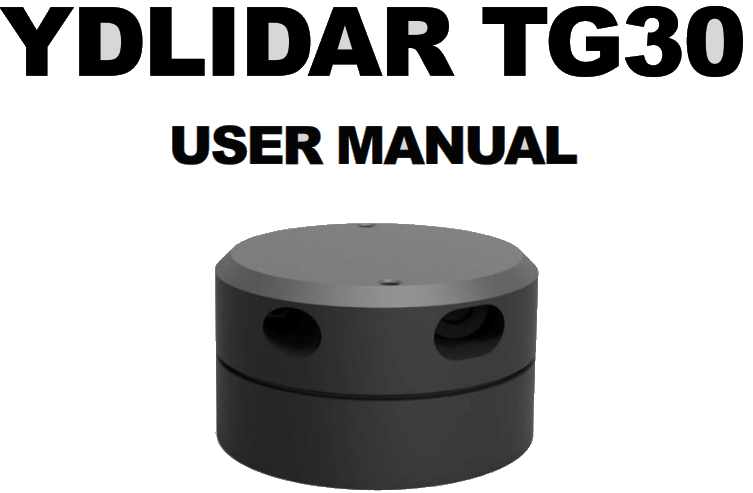
The TG30 development kit has the following components: FIG1 YDLIDAR TG30 DEVELOPMENT KIT
CHART1 YDLIDAR TG30 DEVELOPMENT KIT DESCRIPTION
| Item | Qty. | Description |
| TG30 lidar | 1 | The standard version of the TG30 Lidar. The TG30 has an integrated motor drivefor motor control. |
| USB Type-C Cable | 1 | Use with USB adapter board to connect TG30 and PC. USB cable is both apower supply cable and a data cable. |
| USB AdapterBoard | 1 | USB to UART, PC interconnection.Serial port DTR signal to TG30, motor stopcontrol.USB Type-C Power Interface (PWR) for auxiliary power supply |
Note:USB Adapter board has two USB TYPE C interface:USB_DATA、USB_PWRUSB_DATA: Data-powered interface. In most cases, this interface can be used to meet power and communication requirements.USB_PWR: Auxiliary power supply interface. The USB interface of some development platforms has weak current drive capability. At this time, auxiliary power supply can be used.
USAGE UNDER WINDOWS
Device Connection
When TG30 is evaluated and developed under windows, TG30 and PC need to be interconnected. The specific process is as follows: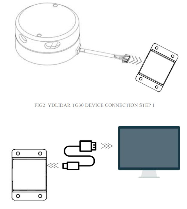 FIG2 YDLIDAR TG30 DEVICE CONNECTION STEP 1
Connect the adapter board with TG30 first, then connect the USB cable to the USB port of the adapter board and the PC. Note that the Type-C interface of the USB cable is connected to the USB_DATA of the USB interface board, and the idle mode is used after TG30 is powered on. The motor does not rotate. If the supply current is not sufficient, please connect with the auxiliary power supply.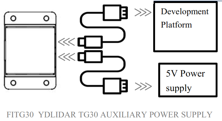 Driver Installation
To evaluate and develop the TG30 under Windows, you need to install the serial port driver of the USB adapter board. The USB adapter board of this kit adopts CP2102 chip to realize serial port (UART) to USB signal conversion. Its driver can be downloaded from our official website or downloaded from the official website of Silicon Labs.http://eaibot.com/http://cn.silabs.com/products/development-tools/software/usb-to-uart-bridge-vcp-driversAfter decompressing the driver package, run the CP2102’s Windows driver installation file (exe file under CP210x_VCP_Windows). Please select the 32-bit version (x86) or 64- bit version (x64) installation program according to the version of the windows operating system.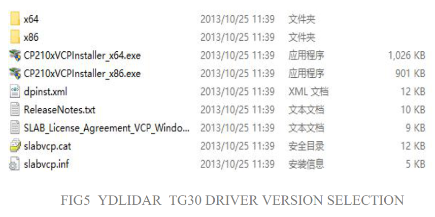 Double-click the exe file and follow the prompts to install it.
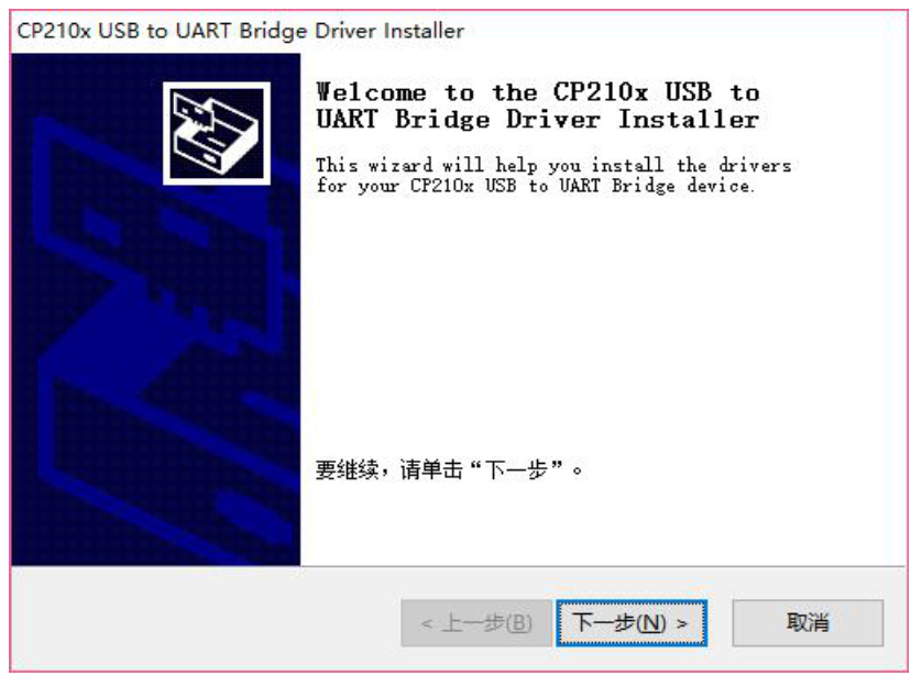 After the installation is complete, you can right-click on [My Computer] and select [Properties].On the open [System] screen, select [Device Manager] from the left menu to access the [Device Manager].Expand [Port] to see the serial port name corresponding to the identified USB adapter, that is, the driver installation is successful. The following figure shows COM3. (Note that the port must be checked in case of TG30 and PC interconnection).Note: Users can also choose Type-C on TG30 to get started quickly. Connect the PC and TG30 directly withType-C data cable, and download the vcp serial port driver of TG30 on the official website. After that, start PointCloud Viewer to scan the map to observed the data.
Evaluation Software Usage
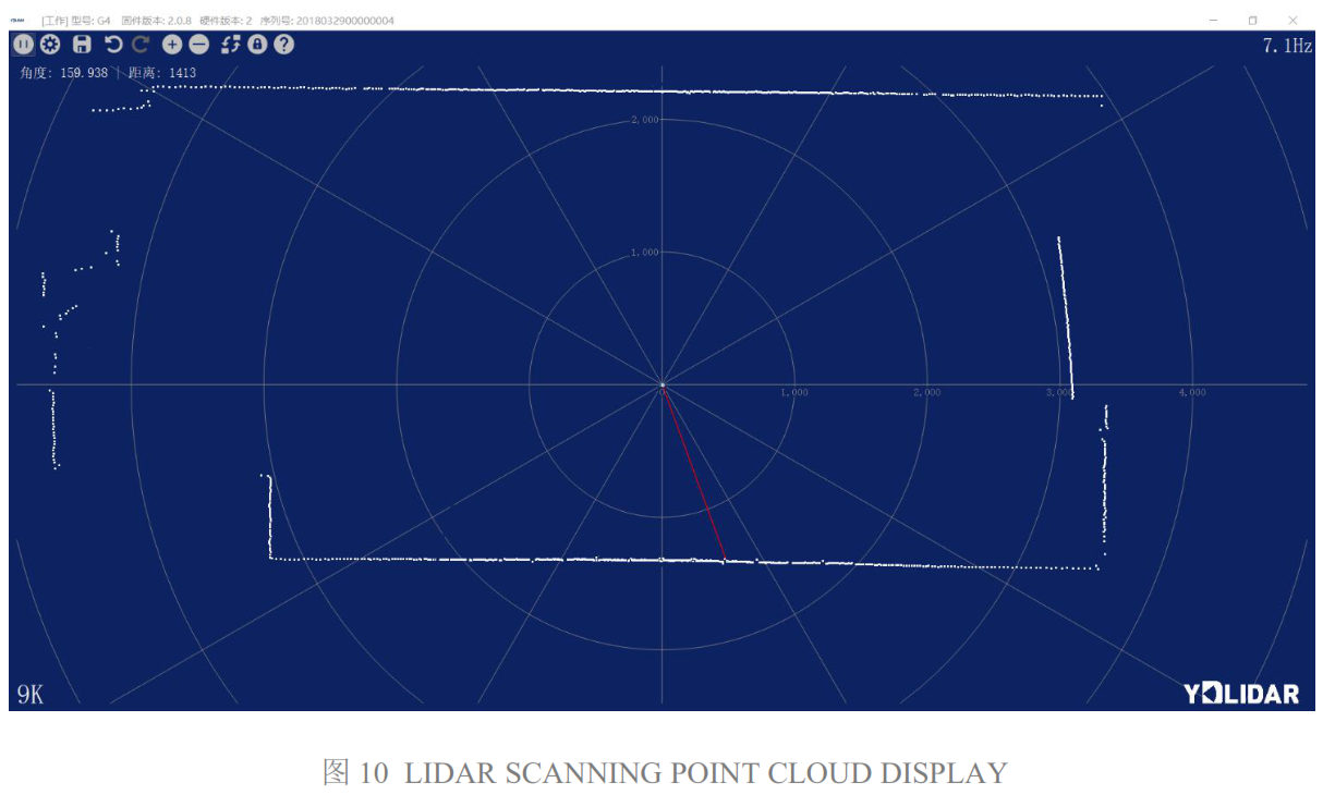
YDLIDAR provides Point Cloud Viewer, a point cloud data visualization software for TG30 real-time scanning. Users can intuitively observe the TG30 scanning effect chart. GDL real-time point cloud data and real-time scanning frequency are provided on YDLIDAR. At the same time, the version information of TG30 can be read, and the scan data can be saved offline to an external file for further analysis.Before using the YDLIDAR software, make sure that the TG30 USB adapter board serial port driver is installed successfully, and interconnect the TG30 with the USB port of the PC. Run the evaluation software: PointCloudViewer.exe, select the corresponding serial port number and model number. You could tick the square box to choose the power-off protection function. Meanwhile, users could choose language and software type in the top right corner.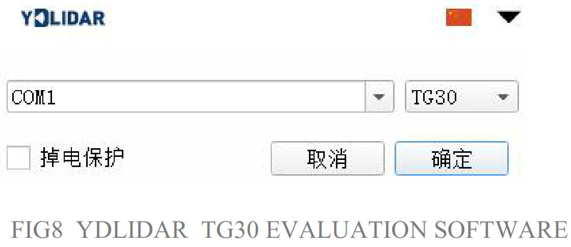 Note: The Lidar does not turn on the power-off protection function by default. This function needs to send the scan command continuously to make it work normally. If the scanning frequency is stopped, the Lidar will stop scanning.If the connection is correct, you will see the following screen:
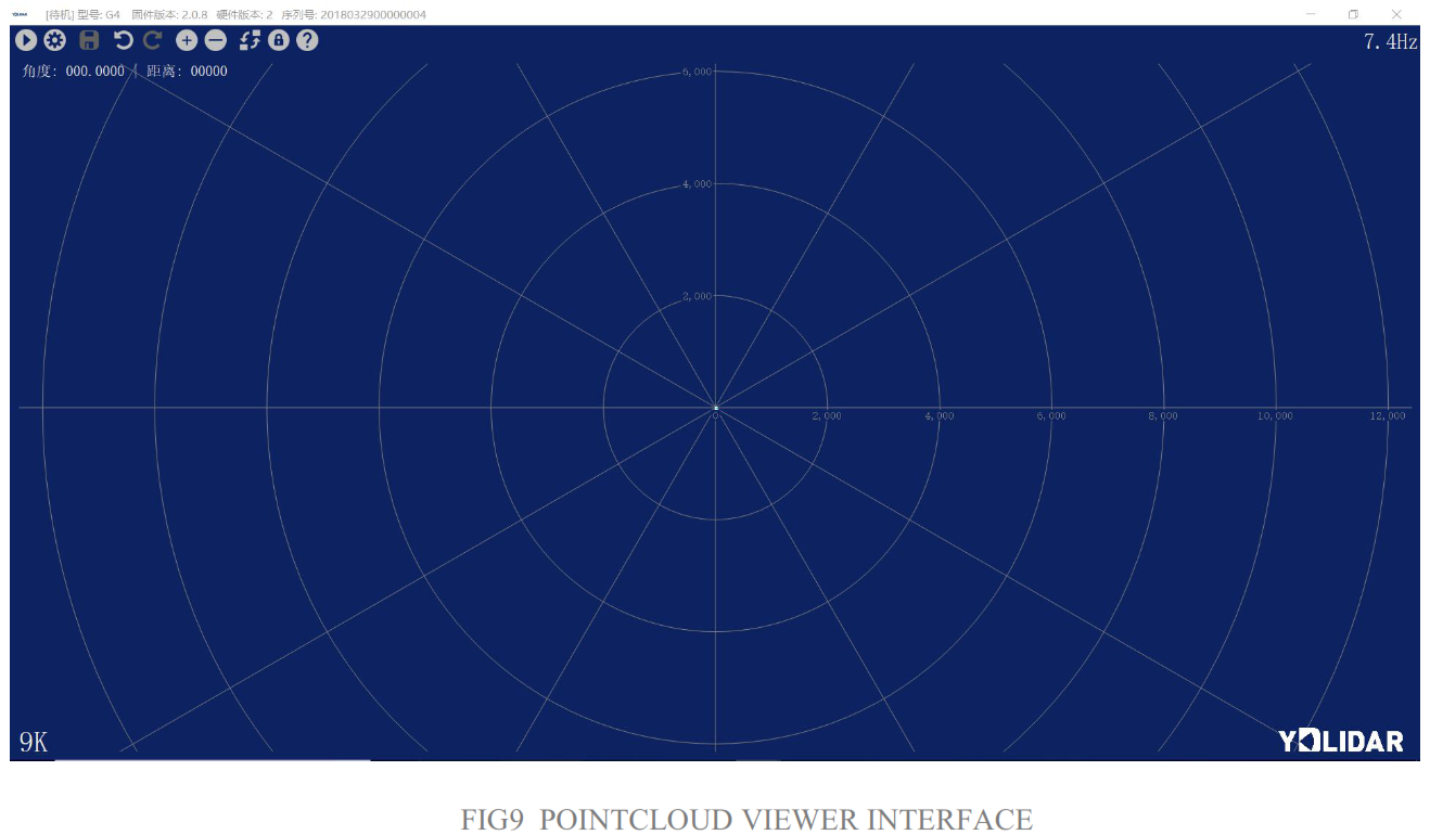 START SCANNING
Click ![]() to start scanning and display the environment point cloud. Click
to start scanning and display the environment point cloud. Click ![]() to stop it.
to stop it.
SYSTEM SETTINGS
Click System Settings ![]() ,and the following settings box will pop up:
,and the following settings box will pop up:
As shown in the figure, you could configure and detect lidar on the setup page, as well as firmware updates and software updates.
SAVE DATA
During lidar scanning, click ![]() ,Save the point cloud data as prompted. The system will save the point cloud information scanned in a circle according to the following format.
,Save the point cloud data as prompted. The system will save the point cloud information scanned in a circle according to the following format.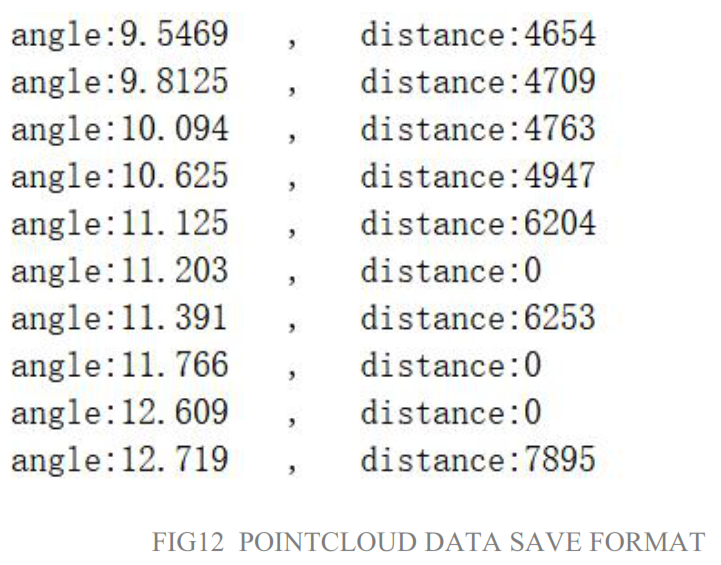 SCANNING DIRECTION
The scanning direction (rotation direction) of the lidar can be adjusted by clicking ![]() . When the lidar is in the scanning state, you need to click the scan control again after switchingthe scanning direction.
. When the lidar is in the scanning state, you need to click the scan control again after switchingthe scanning direction.
SCAN FREQUENCY
![]() is used to adjust the scanning frequency (motor speed) of the lidar. Click any one of them, the system will pop up the frequency setting bar, which can be adjusted automatically according to the demand. When the lidar is in the scanning state, you need to click the scan control again after adjusting the scan frequency.
is used to adjust the scanning frequency (motor speed) of the lidar. Click any one of them, the system will pop up the frequency setting bar, which can be adjusted automatically according to the demand. When the lidar is in the scanning state, you need to click the scan control again after adjusting the scan frequency.
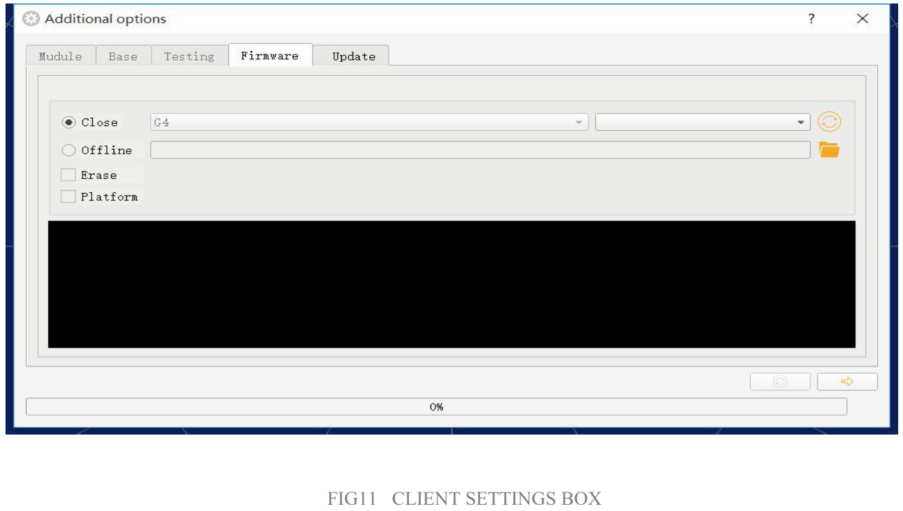
FIRMWARE UPGRADEClick system settings, and choose firmware, as shown in Fig 11. Click![]() to obtain the latest firmware. When there is a new version, click
to obtain the latest firmware. When there is a new version, click![]() to update lidar firmware.Note:During the process of firmware updating, remain normal power supply, stable communication and normal network connection,donot pull out serial port cable.
to update lidar firmware.Note:During the process of firmware updating, remain normal power supply, stable communication and normal network connection,donot pull out serial port cable.
SOFTWARE UPGRADE
The client software will be version-changed and users can update to the latest version for a better experience.Click System Settings and select Update, as shown below: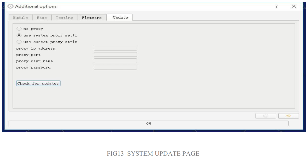
Select the configuration as shown above, click ‘check for updates’, if there is no new version, the system will prompt no update; when there is a new version, the software version informational be filled in the information box, click![]() to update the client software.
to update the client software.
LINUX ROS OPERATIONThere are many Linux versions,this article only uses Ubuntu 16.04, Kinetic version ROS as an example.
Document DescriptionDownload the latest ROS driver package for YDLIDAR TG30 on GitHub.https://github.com/YDLIDAR/ydlidar_ros/tree/TG30
Device ConnectionUnder Linux, the TG30 and PC interconnect processes are consistent with those underWindows. See Device Connection under Window.
ROS Driver InstallationBefore doing the following, make sure that the Kinetic version ROS environment isinstalled correctly.(1) Use the command to create the catkin_ws workspace and copy the ROS driver package ydlidar_ros-TG30 to the catkin_ws/src directory. Switch to the catkin_ws workspace and compile again.
$ mk di r -p ~/ ca tk in _w s/ sr c$ cd ~/ ca tk in _w s$ ca tk in _m ak e
(2) After the compilation is complete, add the catkin environment variable to the ~/.bashrc file and make it effective.
$ ec ho “s ou rc e ~/ ca tk in _w s/ de ve l/ se tu p. ba sh ” >> ~/ .b as hr c$ so ur ce ~/ .b as hr c
(3) Add a device alias /dev/ydlidar to the TG30 serial port.
$ cd ~/ ca tk in _w s/ sr c/ yd li da r/ st ar tu p$ su do ch mo d +x in it en v. sh$ su do sh in it en v. sh
RVIZ Installation
(1) Online installation.
$ su do ap t- ge t in st al l py th on -s er ia l ro s- ki ne ti c -s er ia l g+ + vi m \ro s- ki ne ti c -t ur tl eb ot -r vi z- la un ch er s
(2) If there is a problem with the installation, update the source cache and reinstall it.
$ su do ap t- ge t up da te
RVIZ scan result checkingRun the launch file and open rviz to view the TG30 scan results, as shown in the following figure:
$ ro sl au nc h yd li da r li da r.l au nch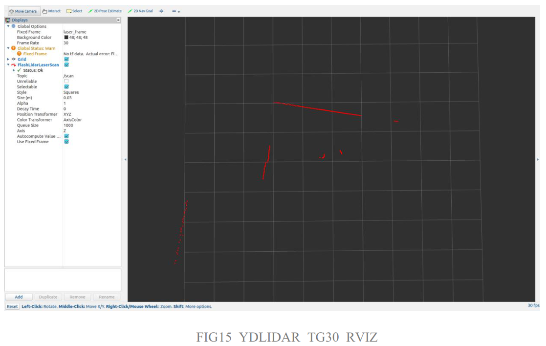
FIG15 YDLIDAR TG30 RVIZ
Modify Scan Angle
The scanning data seen by running the launch file is displayed by default with 360degree data. To modify the display range, you need to modify the configuration parameters in the launch file. The specific operation is as follows:
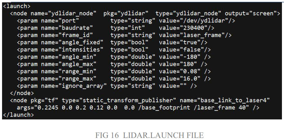
(1) Go to lidar.launch directory and use vim to edit lidar.launch,The contents are as shown in the figure:
$ ro scd yd li da r/l au nc h$ vi m li da r .l au nc h
2)The TG30 lidar coordinates follow the right-hand rule within ROS, with an angle range of [-180, 180]. “angle_min” is the start angle, and “angle_max” is the end angle.The specific scope needs to be modified according to actual use.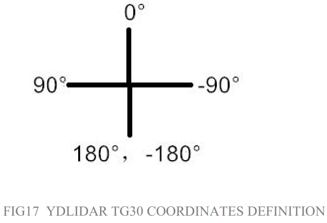 CAUTION
Ambient Temperature
When the working environment temperature of TG30 is too high or too low, it will affect the accuracy of the distance measuring system. It may also damage the structure of the scanning system and reduce the life of the TG30 lidar. Avoid use in high temperature (>50 degrees Celsiuand low temperature (<0 degrees Celsius) conditions.
Ambient lighting
TG30 use 905nm narrow pulse laser source, optimized optical and electric design enables strong light interference resistance, thus it could meet indoor and outdoor application requirements.
Power Supply
During the development process, since the drive current of the USB interface of each platform or the USB interface of the computer may be too low to drive the TG30, the external power supply of the +5V to the TG30 needs to be provided through the USB_PWR interface of the USB interface board. It is not recommended to use mobile phone power bank because the voltage ripple of power bank is too large.
www.ydlidar.com Copyright 2015-2020 YDLIDAR
References
[xyz-ips snippet=”download-snippet”]