Yealink USB PTZ Camera UVC50
Package Contents
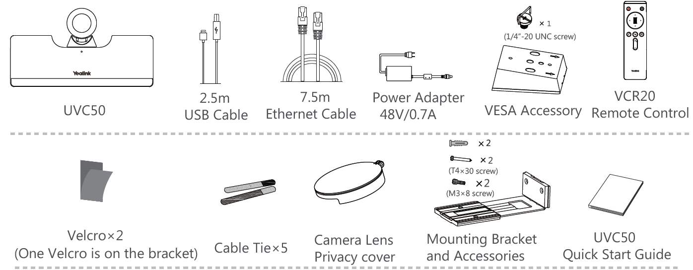
We recommend that you use the accessories provided or approved by Yealink. The use of unapproved third-party accessories may result in poor performance.
UVC50 Installation
- Put on a Flat SurfaceYou can put the UVC50 on the conference table, and make sure that the angle of inclination of the UVC50 is not more than 5 degrees to ensure proper operation.
- Mount on the top of the TVChoose the following installation method when the thickness of the TV is between 1mm and 36mm.

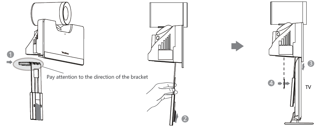
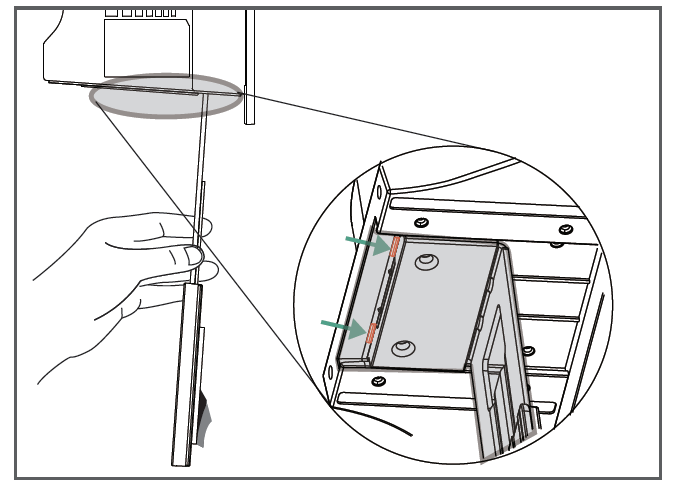
If your UVC50 cannot be mounted on the top of the TV when the bracket has reached the given location, remove the bracket, and then convert the direction of the bracket. Refer to the following section for more information. Choose the following installation method when the thickness of the TV is between 37mm and 77mm.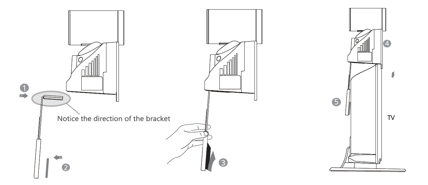
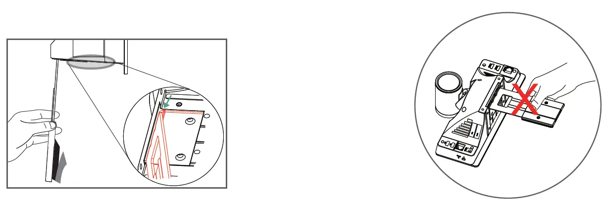
- If your UVC50 cannot be mounted on the top of the TV when the bracket has reached the edge of the UVC50, choose another installation method.
- Do not pick up the bracket which is connected with a UVC50, the UVC50 may fall down in this situation.
Mount on the Wall
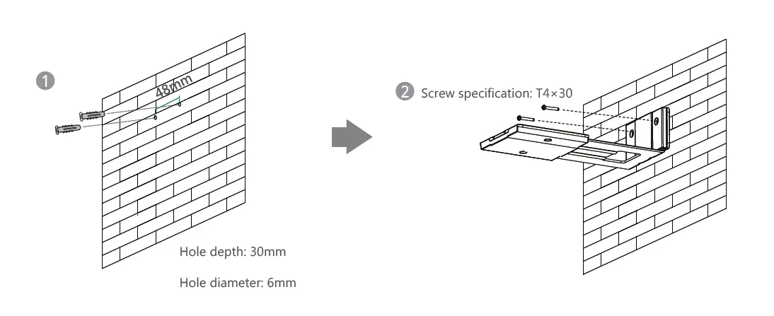
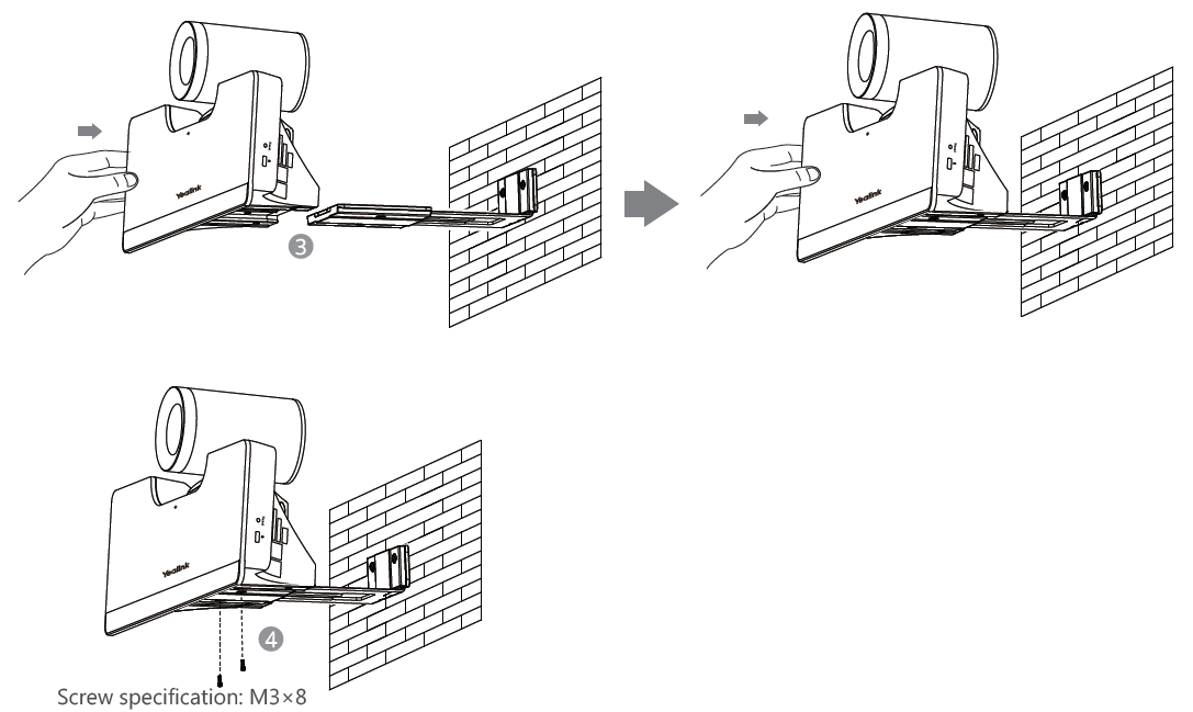
The recommended height is 1.55m-1.85m above the ground.
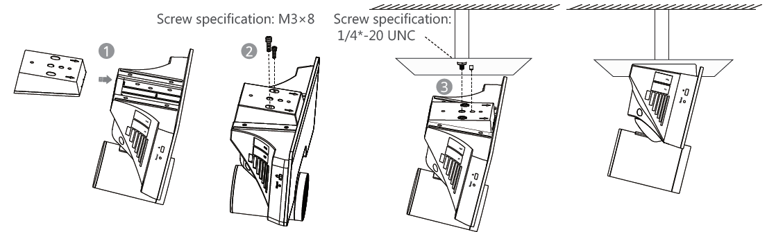
Mount on the Ceiling
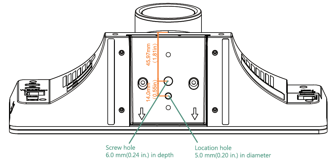
- If you choose the ceiling-mounted installation, you need to purchase a bracket separately. The bracket must meet the following requirements:
- Bear the weight of at least 10.5kg (23.15 lb.) and the thickness must be between 2mm (0.08 in.) and 3 mm (0.12 in.).
- Comes with a location pillar, which can be inserted into the location hole of the VESA accessory. The distance between the screw on the bracket and the location pillar must be 14 mm (0.55 in.).
Mount onto a TV Stand or a Tripod
You need to purchase a TV stand or a tripod separately. The TV stand or the tripod has the same requirements as the bracket used when mounting the UVC50 on the ceiling. The installation steps are the same as the steps of mounting on the ceiling.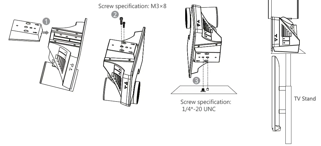
Cable Ties Installation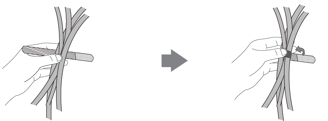
Hardware Interface Instructions
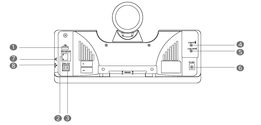
- USB: insert DD10 to connect to CPW90
- Microphone(optional): connect to VCM34
- Video Out: connect to a PC as video output
- Line In: connect to an audio input device using an audio cable (3.5mm)
- Line Out: connect to an audio output device using an audio cable (3.5mm)
- DC48V: connect to the power adapter
- Reset: reset the UVC50 to factory defaults
- Security slot: connect a universal security cable to the UVC50 so that you can lock the UVC50 down.
UVC50 Connection
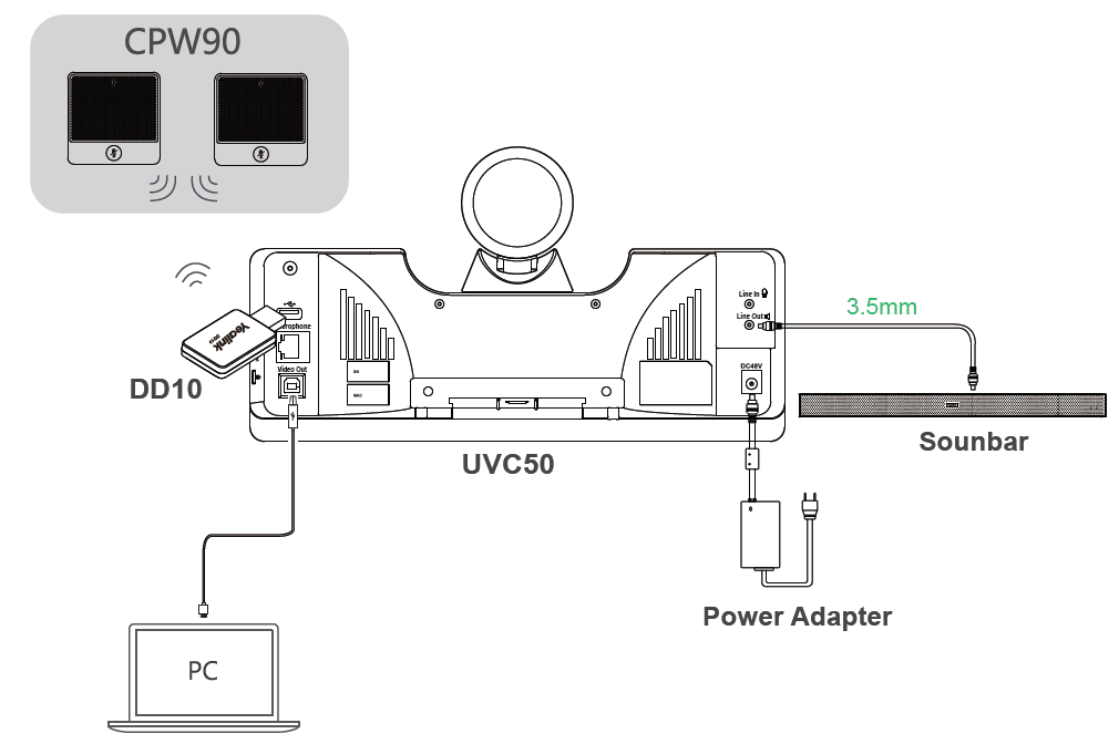
- The priority of audio input channel is: Microphone(VCM34) >USB(CPW90)>line-in.
- The cable should be replaced at once if its skin is broken.
LED Indicator Instructions
LED indicators on the UVC50:
| LED Status | Description |
| Solid green | The UVC50 is active. |
| Solid red | The UVC50 is in sleep mode. |
| Solid orange | The UVC50 is initializing. |
| Flashing orange | The UVC50 is upgrading firmware. |
![]()
References
[xyz-ips snippet=”download-snippet”]