
Yealink UVC40 USB Video Conferencing Endpoint User Guide
USB Video Conferencing Endpoint
Package Contents
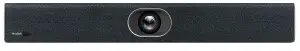
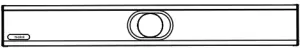
- UVC 40

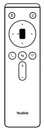
- VCR20 Remote Control
- AAA Battery×2
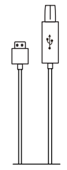
- 7m USB Cable
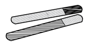
- Cable Tie×5
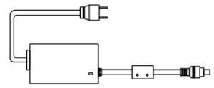
- Power Adapter
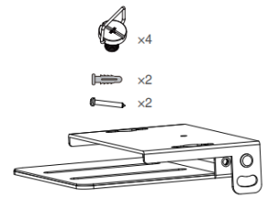
- Mounting Bracket and Accessories
- Silicone Pad×2
- Quick Start Guide


- We recommend that you use the accessories provided or approved by Yealink. The use of unapproved third-party accessories may result in reduced performance.
- Use the Yealink original power adapter (48V/0.7A) to charge the endpoint only. The use of the third-party power adapter may cause the damage to the endpoint.
- The USB cable in the MVC400/ZVC400 package is 2.5 meters long.
UVC40 Installation
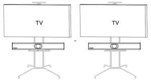
- Put on a Flat Surface
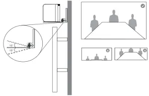
- Mount on a Wall Placing UVC40Mount the UVC40 below the TV when the mounting height of the TV is higher than 120cm.Mount the UVC40 above the TV when the mounting height of the TV is lower than 120cm.
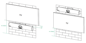 Mount the UVC40 below the TV when the mounting height of the TV is higher than 120cm.Mount the UVC40 above the TV when the mounting height of the TV is lower than 120cm.
Wall Mounting
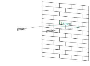
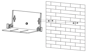
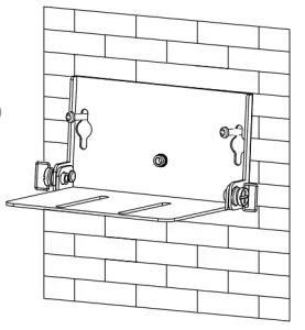
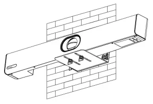
Use the bracket to mount your endpoint on a wall. The mounting height affects your camera view. The recommended height is 1.1m above the ground.Step1:Assemble the mounting bracket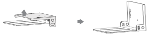
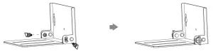
Step2:Mount the UVC40 to the wall
- Hole depth: 30mm Hole diameter: 6mm
- T4×30 screws
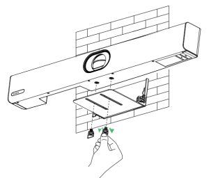
Adjusting the Camera Tilt
Remote Control and Cable Ties Installation
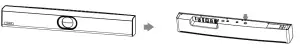
Remote Control Installation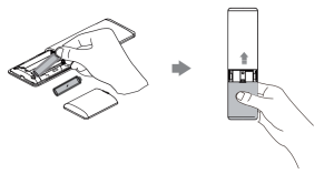
Cable Ties Installation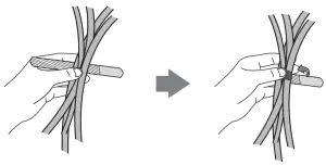
Hardware Interface Instructions
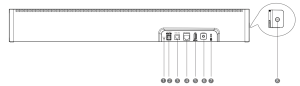
- Reset: reset the UVC40 to factory defaults.
- DC48V: connect to the power adapter.
- Video Out: connect to a PC as video output.
- Microphone: connect to the microphone (for exmaple, VCM34).
- USB: insert DD10 to connect to CPW90 if needed.
- Line In: connect a 3.5mm audio connector to use the UVC40 as an audio output device.
- Security slot: connect a universal security cable to the UVC40 so that you can lock the UVC40 down.
- Pairing key: press the pairing key to pair the CPW90 wireless microphone.
UVC40 Connection
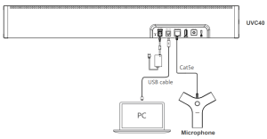
- The priority of audio input channel is; Microphone (VCM34) >USB(CPW90).
- The cable should be replaced at once if its skin is broken.
LED Indicator Instructions
LED indicators on the UVC40:
|
LED Status |
Description |
| Off | The UVC40 is not properly connected to the mini-PC. |
| Flashing green | There is an incoming call. |
| Solid green | The UVC40 is active. |
| Solid red | The UVC40 is muted. |
| Solid orange | The UVC40 is initializing or in sleep mode. |
| Flashing orange | The UVC40 is upgrading firmware. |
| Flashing red andgreen alternately | The UVC40 is paired with the CPW90 |
| Flashing red | The UVC40 is in recovery mode and the firmware has not been upgraded. |
References
[xyz-ips snippet=”download-snippet”]