Multiple Sound Siren PSE04


Built-in high accuracy Temperature sensorThe PSE04 is a wireless siren, based on Z-Wave technology. It is the Z-Wave Plus TM product, it supports the security, OTA… Those newest features of the Z-WaveTM is a wireless communication protocol designed for home automation, specifically to remotely control applications in residential and light commercial environments. The technology uses a low-power RF radio embedded or retrofitted into home electronics devices and systems, such as lighting, home access control, entertainment systems, and household appliances.TM technology. Z-WaveTM This product can be included and operated in any Z-Wave network with other Z-WaveTM TM-certified devices from other manufacturers and/or
other applications. All non-battery-operated nodes within the network will act as repeaters regardless of vendor to increase the reliability of the network. The device adopt the Z-WaveTM 700 series chip when your Z-WaveTM network system is all made by Z-Wave 700 series devices. The network system will have the advantages as below.TM
- Concurrent multi-channel support reduces external interference.
- Better RF range, improve about 10 meters in indoor.
- Support 100 Kbps transmit speed, speed up communication.
Specification
| Rating | 6VDC (AA Battery *4) |
| RF distance | Min. 40M indoor,
100M outdoor line of sight, |
| RF Frequency | 868.40 MHz, 869.85 MHz(EU) 908.40 MHz, 916.00 MHz(US) 920.9MHz, 921.7MHz, 923.1MHz (TW/KR/Thai/SG)921.40 MHz, 919.80 MHz(ANZ) 869.00 MHz(RU)865.20 MHz(IN)916.00 MHz(IL) |
| RF Maximum Power | +10dBm (Peak), -10dBm (Average) |
| Dimension | 170mnn(L) X 48mm (W) X 30(H) |
| Weight | 205g |
| IP classification | IP44; Outdoor use |
| Operation temperature | -20 to 55° C |
| Humidity | 85%RH max |
| FCC ID | RHHPSE04 |
| Marking | CE/NCC |
- Specifications are subject to change and improvement without notice.
Troubleshooting
| Symptom | Cause of Failure | Recommendation |
| The device can not ‘n to Z-Wave\’” network | The device may be in a Z- Wave\’” network. | Exclude the devicethen induce again. |
Overview
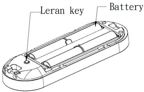
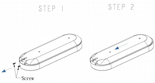
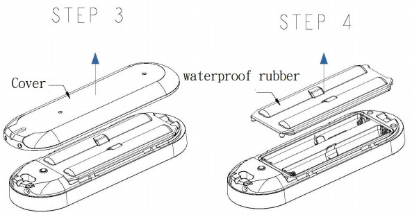
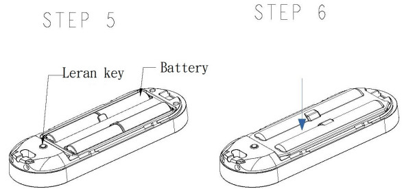
Battery InstallationWhen the device reports a low battery message. The user should replace the battery to the new one. The battery type is AA, 1.5V Please loosen the screw on the back cover to release the front cover
 |
 |
 |
 |
Adding to Z-WaveTM Network
There is one tamper key on the device. The tamper key can add, remove, reset from the Z-WaveTM network.In the first time, add the device into the Z-Wave network. First, make sure the primary controller is in the add mode. And then power on the device. The device will auto start the SmartStart Inclusion mode.Notice: Including a node ID allocated by Z-Wave Controller means “Add” or “Inclusion”. Excluding a node ID allocated by Z-WaveTM Controller means “Remove” or Exclusion”.TM
| Function | Description |
| Add | 1. Have ZWaveTM Controller entered inclusion mode.
2. Pressing the tamper key three times within 1.5 seconds to enter the inclusion mode. 3. After add successfully, the LED will light ON 1 second |
| Remove | 1. Have Z-WaveTM Controller entered exclusion mode.
2. Pressing the tamper key three times within 1.5 seconds to enter the exclusion mode. 3. Node ID has been excluded. |
| Reset | Notice: Use this procedure only in the event that the primary controller is lost orotherwise inoperable.1. Pressing the tamper key four times within 1.5 seconds and do not release the tamper key in the 4th pressed, and the LED will light ON.2. After 3 seconds the LED will turn OFF, after that within 2 seconds, release the tamper key. If successful, the LED will light ON one second. Otherwise, the LED will flash once.3. IDs are excluded and all settings will reset to factory default. |
|
SmartStart
|
1. Product has a DSK string, you can key in the first five-digit to increment the SmartStart process, or you can scan the QR code.
Ex:mydsk 10209-46687-52248-13629-04783-07465-15776-56519 2. SmartStart enabled products can be added into a Z-Wave network by scanning the Z-Wave QR Code present on the product providing SmartStart inclusion. No further action is required and the SmartStart product will be added automatically within 10 minutes of minutes On in the network vicinity. *notice:The QR code can be found on the device PSE04 or on the box. |
| Association | This machine provides one group of nodes. Each group can set 1 Node.Group 1 is called Lifeline the device will report :1. Notification report2. Sensor multilevel report3. Device Reset Locally Notification4. Battery Report5. Indicator Report |
|
Notice 1: Always RESET a Z-Wave device before trying to add it to a Z-WaveTM network.
LED Light IndicationThe LED light indicates the different modes of the PSE04
| State Type | LED Indication |
| Without Node ID | Under normal operation, when the PSE04 has not been allocated a node ID, the LED light will flash on and off alternately at 0.5-second intervals. By pressing the On/Off button, the LED light will stop flashing temporarily. |
| Learning | Slow flashes once when learning is successful. |
| Alarm Trigger | All LED flashes until trigger off. |
Z-WaveTM Message ReportIn default, the device will use Notification Report to represent the tamper trigger event.* Tamper Report:When the tamper key is pressed over 5 seconds. The device will into the alarm state. In that state, if the tamper key be released, the device will unsolicited to send the report to the nodes in group 1.
| Notification Report (V8) |
| Notification Type: Home Security (0x07)
Event: Tampering. Product covering removed (0x03) |
* Siren State Report:When the siren starts playing or stops the alarm sounds, the device will unsolicited to send the “Notification Report” to the nodes in group 1.
| Notification Report (V8) |
| Notification Type: Siren (0x0E)
Event: Siren active (0x01) , Siren idle (0x00) |
*Temperature Report:
When the temperature differential over, the device will unsolicited to send the “Sensor Multilevel Report” to the nodes in the Lifeline group. Sensor Type: Temperature (0x01)*** Temperature differential report ***
This function default is disabled, to enable this function by setting the configuration NO.5 is greater than 0.The default, is disable temperature differential report.If setting the configuration NO.5 to 1, when the temperature is changed to plus or minus one degree Celsius (1.8 degree Fahrenheit), the device will report temperature information to the nodes in the l Lifeline group.The device will measure the temperature in every 10 seconds.Notice 1: The PSE04 must stay awake for at least 2 seconds after communicating, so therefore the more communication, the power consumption fast, please pay attention to use configuration NO.5.Notice 2: This product cannot reflect outdoor temperature immediately because of the temperature sensor equipped inside rather than the surface.
*Play Sound:Using the BASIC_SET or Sound_Switch_Tone_Play_Set to play the siren, BASIC_SET or Sound_Switch_Tone_Play_Set with Value 0xFF, the Sound ID will be the same as the value which was set in Configuration No.7, 0x00 will stop to play.
Basic Set (V2) or Sound Switch Tone Pley Set (V1)
| Value | Sound |
| 0x00 | Stop Play |
| 0x01 | Fire |
| 0x02 | Ambulance |
| 0x03 | Police |
| 0x04 | Alarm |
| 0x05 | Ding Dong |
| 0x06 | Beep |
| 0xFF | Same as configuration NO.7 setting, or sound switch configuration setting. |
* Timing Report:
Besides the event triggered could report message, the device also supports the timing unsolicited report of the status.
- Battery level report: Every 6 hours report once in default. It could be changed by setting configuration NO. 6.
- Low battery report: When the battery level is too low, every 30 minutes will report once.
- Temperature report: Every 6 hours report once in default. It could be changed by setting the configuration NO. 4.
Notice: Configuration NO. 4 and 6 could be setting to zero to disable the auto report. And configuration NO. 1 could change the tick interval, the default value is 30, if setting to 1, that means the minimum auto report interval will be one minute. And please notice if setting this value to zero, that means disable all of the timing report except the low battery detection.Power Up Procedure*Battery Power Check
When the device power-up, the device will detect the power level of the battery immediately. If the power level is too low, device will report low battery even every 30 minutes. Please change to another new battery.*Wake up beam
If a Z-Wave controller or another node in the network needs to communicate with a battery-powered device such as a door lock, the controller sends a special beam signal. The purpose of this beam is to wake up the FLiRS device.When the first device receives this beam, it immediately fully wakes up and then communicates with the controller or other Z-Wave device utilizing standard Z-Wave protocol commands. If the device does not hear a Beam it goes back to full sleep for another period until it partially awakes again and listens for a Beam.
Over The Air (OTA) Firmware Update
The device is supported with Z-Wave™ firmware update via OTA.
- Set the Z-WaveTM Controller into the firmware update mode.
- Choose the hex file to update the firmware.
- Wait 10~15 minutes for completing the OTA process.
- The result of OTA will show in the Z-Wave™ Controller log.
During the OTA process, please DO NOT remove the power, otherwise, the firmware will be broken, and the device will be nonfunctional.
| NO. | Name | Def. | Valid | Description |
| 1 | Auto Report
Tick Interval |
0x1E | 0~255 | The interval time for auto-report each tick. |
| 2 | Sound
Duration |
0x06 | 0~255 | Play sound duration, 1 tick is 30 seconds. |
| 3 | Customer
Function |
0x00 | All | Customer function switch, using bit control. |
| 0 | Bit0: Disable Trigger Alarm. 0:Enable, 1:Disable. | |||
| 0 | Bit1: Disable Sound. Only using the optical alarm. 0:Enable, 1:Disable. | |||
| 0 | Bit2: Temperature Unit.0:Fahrenheit, 1:Celsius. | |||
| 0 | Bit3: Reserve. | |||
| 0 | Bit4: Reserve. | |||
| 0 | Bit5: Reserve. | |||
| 0 | Bit6: Reserve. |
| 0 | Bit7: Reserve. | |||
| 4 | Auto Report Temperature Time | 0x0C | 0-255 | The interval time for auto report the temperature. |
| 5 | Temperature Differential Report | 0x00 | 0255 | The temperature differential to report. |
| 6 | Auto Report Battery Time | 0x0C | 0— 255 | The interval time for auto report the battery level. |
| 7 | Play Sound Control | 0x43 | All | Control play sound’s level and which sound. |
| 3 | BitBrut Play sound’s level. Level 1-3, 0: Level 3. | |||
| 0 | Bit2: Reserve. | |||
| 0 | Bit3: Reserve. | |||
| 4 | Bit40•7: Which sound id will play when control forms controller. Sound ID 1-6, 0: Disable. |
Z-Wave Supported Command Class
| Command Class | Version | Required Security Class |
| Z-Wave Plus™ Info | 2 | None |
| Security | 1 | None |
| Security 2 | 1 | None |
| Supervision | 1 | None |
| Transport Service | 2 | None |
| Association | 2 | Highest granted Security Class |
| Association Group
Information |
3 | Highest granted Security Class |
| Device Reset Locally | 1 | Highest granted Security Class |
| Firmware Update Meta
Data |
5 | Highest granted Security Class |
| Indicator | 3 | Highest granted Security Class |
| Manufacturer Specific | 2 | Highest granted Security Class |
| Multi-Channel Association | 3 | Highest granted Security Class |
| Powerlevel | 1 | Highest granted Security Class |
| Version | 3 | Highest granted Security Class |
| Configuration | 4 | Highest granted Security Class |
| Sensor Multilevel | 11 | Highest granted Security Class |
| Basic | 1 | Highest granted Security Class |
| Notification | 8 | Highest granted Security Class |
| Sound Switch | 1 | Highest granted Security Class |
| Battery | 1 | Highest granted Security Class |
 WarningCaution, avoid listening at high volume levels for long periods
- The suitable ambient temperature for the module/device is 0°C~40°C.
- Do NOT place the module/device direct under sunlight, in a humid place or in any location where they may contact moisture, dirt, dust.
- Do NOT place the module/device where exists combustible substances or any source of heat, fires, radiators, boiler, etc.
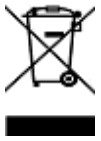 This marking indicates that this product should not be disposed of with other household wastes throughout the EU. To prevent possible harm to the environment or human health from uncontrolled waste disposal, recycle it responsibly to promote the sustainable reuse of material resources. To return your used device, please use the return and collection systems or contact the retailer where the product was purchased. They can take this product for environmentally safe recycling.
- Reorient or relocate the receiving antenna.
- Increase the separation between the equipment and receiver.
- Connect the equipment into an outlet on a circuit different from that to which the receiver is connected.
- Consult the dealer or an experienced radio/TV technician for help. This device complies with Part 15 of the FCC Rules. Operation is subject to the following two conditions:1.This device may not cause harmful interference, and2. This device must accept any interference received, including interference that may cause undesired operation.FCC Caution: Any changes or modifications not expressly approved by the party responsible for compliance could void the user’s authority to operate this equipment.This transmitter must not be co-located or operating in conjunction with any other antenna or transmitter.
References
[xyz-ips snippet=”download-snippet”]