Instruction BulletinGDE7796300SQR50101**Z Z-WaveTM Plus Remote Dimmer Switch** = color code: WH (white), LA (light almond), BK (black), GY (gray)
Features
- Wireless Z-Wave technology creates a mesh network for command and control interoperability with other Z-Wave compliant controllers and devices.
- Work with other Z-Wave switch or dimmer devices for 3-way (multi-location) control, provide manual and remote control.
- The 3-way control can be achieved through below 2 methods.o Association group control oro Central scene control
- Child lockout capability.
NOTE: This remote switch is only a wireless controller, it cannot be used by itself for single-pole control.
| Specification of SQR50101**Z Z-Wave Plus Remote Dimmer Switch | |
| Voltage | 120 Vac, 60 Hz |
| Operating temperature | 32–104°F (0–40°C) |
| Wireless type | Z-Wave (Support S2 and SmartStart) |
| Wireless frequency | 908.40 MHz / 908.42 MHz / 916 MHz |
1Suitable for at least 90°C.
Precautions
CAUTIONHAZARD OF UNINTENDED USEThis device is intended to be used for non-critical automation activities. It is not intended to support life, safety, or medical equipment.Failure to follow these instructions can result in personal injury or equipment damage.![]() DANGER
DANGER
HAZARD OF ELECTRIC SHOCK, EXPLOSION, OR ARC FLASH
- Apply appropriate personal protective equipment (PPE) and follow safe electrical work practices. See NFPA 70E, NOM-029-STPS or CSA Z462 or local equivalent.
- This equipment must only be installed and serviced by qualified electrical personnel.
- Turn off all power supplying this equipment before working on or inside equipment.
- Always use a properly rated voltage sensing device to confirm power is off.
- Use with copper wire only.
- Indoor use only.
- Replace all devices, doors, and covers before turning on power to this equipment.
Failure to follow these instructions will result in death or serious injury.
![]() WARNING
WARNING
HAZARD OF HEAT AND FIRE DAMAGERead all instructions before installation. The manufacturer will not be held responsible for product damage resulting from not following the instructions.
- Wet hands are strictly prohibited.
- Do not continue working after self-disassembly of any nature and damage of external forces.
Failure to follow these instructions can result in death, injury or equipment damage.
![]() WARNING: This product can expose you to chemicals including Carbon black, which is known to the State of California to cause cancer, and Bisphenol A (BPA), which is known to the State of California to cause birth defects or other reproductive harm. For more information go to www.P65Warnings.ca.gov.
WARNING: This product can expose you to chemicals including Carbon black, which is known to the State of California to cause cancer, and Bisphenol A (BPA), which is known to the State of California to cause birth defects or other reproductive harm. For more information go to www.P65Warnings.ca.gov.
Wireless Range Conditions
The wireless range is the effective distance of remote control and it will be impacted by the following conditions:
- Each wall or obstacle (e.g., refrigerator, TV, etc.) between the remote or ZWave device and the destination device will reduce the wireless range.
- Brick, tile, or concrete walls block more of the wireless signal than walls made of wooden studs and plasterboard (drywall).
- The angle of direction between the remote or Z-Wave device and the destination device will also impact the wireless range; normally, placing the ZWave devices face-to-face will get the best wireless range.
- Wall-mounted Z-Wave devices installed in metal junction boxes may suffer a significant loss of range since the metal box blocks a large part of the wireless signal.
Installation
- Turn the power OFF at circuit breaker or fuse and test that power is off before wiring.
- Wire the device according to the wiring diagram (Figure 1).
- Check that all connections are tight and no bare wires exposed.
- Install the device into the standard outlet box using the screws provided.
- Install the plate (not included) (Figure 2).

- Restore power. Figure
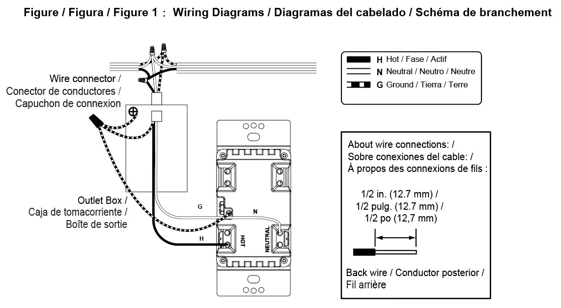
Figure 2: Wall Plate

Operation
The remote switch can only control other Z-Wave devices after it is added into a Z-Wave network.
Figure 3: Operation
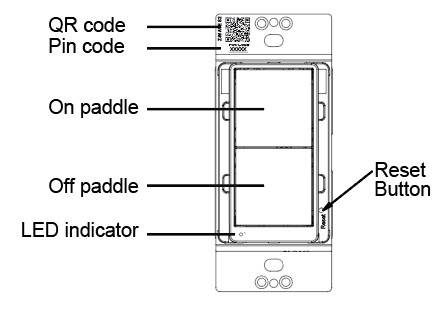
- Inclusion in a Z-Wave network:NOTE: The device supports S2-authenticated and S2-unauthenticated inclusion method. It is highly recommended to only select S2-authenticated or the highest inclusion method and deselect other methods. This ensures the highest security level during Z-Wave service. During S2-authenticated inclusion, users may be asked to scan the QR code or enter a 5-digit pin code attached on the device.A. SmartStart inclusion: The feature assumes the gateway has implemented SmartStart. Users could use the APP of the gateway or the gateway camera to scan the QR code on device or on the enclosed label inside the package before powering on the device, and then when the device is powered on, it shall be automatically added to the gateway.B. Manual inclusion (Figure 4): When the gateway is in adding mode (please refer to the instruction of the Z-Wave gateway for the operations on gateway itself), quick click the upper paddle or lower paddle 3 times within 1.5 seconds.Note: Please do not power cycle the device during the inclusion process.
- Exclusion from a Z-Wave network (Figure 4):When the gateway is in removing mode (please refer to the instruction of the Z-Wave gateway for the operations on gateway itself), quick click the upper paddle or lower paddle 3 times within 1.5 seconds.Figure 4: Join or Leave the Z-Wave Network
- Group control the nodes of association group 2 (Figure 5):– One short tap on upper paddle: turn on the grouped Z-Wave switch / dimmer devices– One short tap on lower paddle: turn off the grouped Z-Wave switch / dimmer devicesNOTE: – Please refer to association setting for nodes group 2 setup. This requires a gateway with advanced features and assumes the device is included in a network.Figure 5: Group Control, Association Group 2
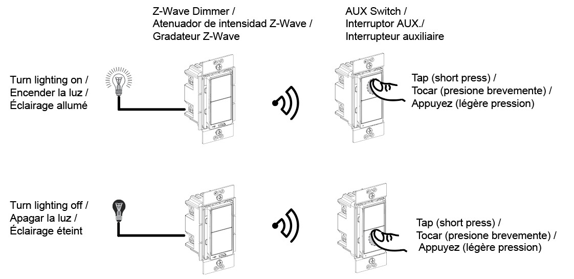
- Group control the nodes of association group 3:On/Off control (Figure 6):– One short tap on upper paddle: turn on the grouped Z-Wave dimmer devices to last status– One short tap on lower paddle: turn off the grouped Z-Wave dimmer devices
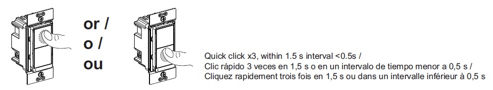
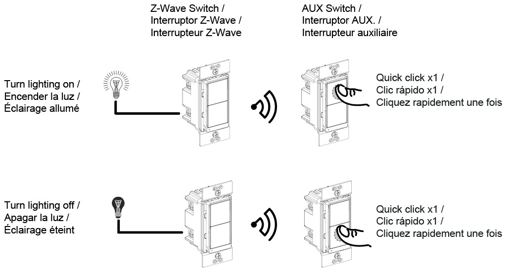
Figure 6: Group Control, Association Group 3
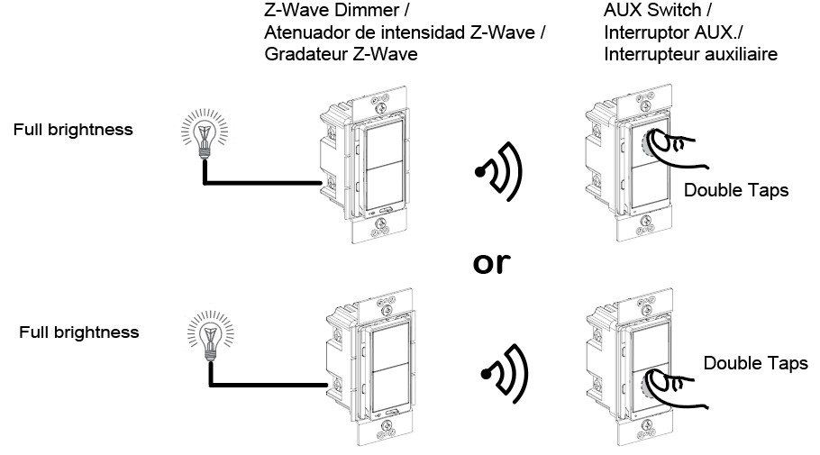
Quick to full brightness (Figure 7):Double taps on any paddle: turn on the lighting to full brightness connected to the grouped Z-Wave dimmers.
Figure 7: Group Control, Association Group 3, Full Brightness Control
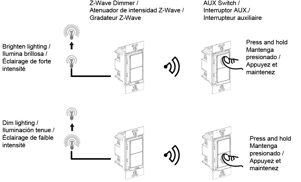
Dimming control (Figure 8):– Long press on upper paddle: dim up the lighting connected to the grouped dimmers– Long press on lower paddle: dim down the lighting connected to the grouped dimmersNOTE:– Please refer to association setting for nodes group 2 setup. This requires a gateway with advanced features and assumes the device is included in a network.– It is recommended to use group dimmer devices in group 3 setup for 3-way dimming control, as group 2 can only support on/off control
Figure 8: Group Control, Association Group 3, Dimming Control
5. Scene Control :Different operations on different paddles trigger various scenes set in the gateway. Please refer to the “Central Scene Capacity” Table.NOTE: – Please refer to central scene-setting for scenes setup. This requires a gateway withadvanced features and assumes the device is included in a network.
Central Scene Capacity
| Actions | Report Content | |
| Upper paddle | 1x tap | keyAttributes: 0, sceneNumber: 1 |
| 2x taps | keyAttributes: 3, sceneNumber: 1 | |
| Long press | keyAttributes: 2, sceneNumber: 1 | |
| Press released | keyAttributes: 1, sceneNumber: 1 | |
| 4 x taps | keyAttributes: 5, sceneNumber: 1 | |
| 5 x taps | keyAttributes: 6, sceneNumber: 1 | |
| Lower paddle | 1x tap | keyAttributes: 0, sceneNumber: 2 |
| 2x taps | keyAttributes: 3, sceneNumber: 2 | |
| Long press | keyAttributes: 2, sceneNumber: 2 | |
| Press released | keyAttributes: 1, sceneNumber: 2 | |
| 4 x taps | keyAttributes: 5, sceneNumber: 2 | |
| 5 x taps | keyAttributes: 6, sceneNumber: 2 |
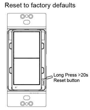
6. Reset to factory defaults (Figure 10):Long press the reset button for >20 seconds till the blue LED blink 5 times within one second.NOTE:
- Use this procedure only when the Z-Wave gateway is missing or otherwise inoperable.
- Reset the device to factory default settings will set the device to not in Z-Wave network state, delete the association setting and restore the configuration setting to the default.
Figure 10: Reset to Factory Defaults
Advanced Setting
The advanced setting requires an advanced gateway. Basic gateway does not support this setting. Users can do the setting through the interface of the advanced gateway.All configuration parameters can be restored to factory default settings by the gateway or by manual reset.
| Configuration | |||||
| Parameter No. | Size | Description | Valid Value | Default Value | Unit |
| 1 | 1 byte | Child Lockout | 0= Disable1= Enable | 0 | N/A |
Association
| Grouping ID | Max. No. of Nodes | Description |
| 1 | 5 | 1. Central Scene Notification2. Device Reset Locally3. Indicator Report |
| 2 | 5 | Basic Set |
| 3 | 5 | SWITCH_MULTILEVEL_SETSWITCH_MULTILEVEL_START_LEVEL_CHANGESWITCH_MULTILEVEL_STOP_LEVEL_CHANGE |
LED Indication
| Blue LED flashing | LED blinks slowly (once per 3 seconds) for 3 minutes: device not in networkLED stays on for 1 minute: device in the network
LED blinks once per second: adding/leaving networkLED blinks 3 times within one second: signal for releasing the reset buttonLED blinks 4 times within 2 seconds: start to perform reset processLED blinks quickly (twice per second) for 5 seconds: device receive OTA command or OTA fail |
| Blue LED on | The paddle is pressed |
| Blue LED off | The paddle is released |
Trouble Shooting
| Issue | Solution |
| SmartStart inclusion taking too long | Power cycle the device to escalate the inclusion. |
| Inclusion is unsuccessful | Move the gateway closer to the device and repeat the inclusion operation. |
FCC Compliance Statement
Federal Communication Commission Interference StatementThe equipment has been tested and found to comply with the limits for a class B Digital Device, pursuant to part 15 of the FCC Rules. These limits are designed to provide reasonable protection against harmful interference in a residential installation. This equipment uses, generates and can radiate radio frequency energy and, if not installed and used in accordance with the instruction, may cause harmful interference to radio communication. However, there is no guarantee that interference will not occur in a particular installation. If this equipment does cause harmful interference to radio or television reception, which can be determined by turning the equipment off and on, the user is encouraged to try to correct the interference by one or more of the following measures:-Reorient or relocate the receiving antenna.-Increase the separation between the equipment and receiver.-Connect the equipment into an outlet on a circuit different from that to which the receiver is connected.-Consult the dealer or an experienced radio/TV technician for help.
FCC Radiation Exposure Statement:This equipment complies with FCC radiation exposure limits set forth for an uncontrolled environment. This equipment should be installed and operated with minimum distance 20cm between the radiator & your body.RF Exposure: A distance of 20 cm shall be maintained between the antenna and users, and the transmitter module may not be co-located with any other transmitter or antenna.Non-modification Statement:Any changes or modifications not expressly approved by the party responsible for compliance could void the user’s authority to operate this equipment.
FCC Supplier’s Declaration of ConformityProduct Name: ZWAVE+ AUX SWITCH
Model Number: SQR50101WHZ, SQR50101LAZ, SQR50101BKZSuppliers Name: Schneider ElectricSuppliers Address (USA): 800 Federal Street Andover, MA 01810 USASuppliers Website: www.se.com/usFCC Compliance Statement
This device complies with part 15 of the FCC Rules. Operation is subject to the following two conditions: (1) This device may not cause harmful interference, and (2) this device must accept any interference received, including interference that may cause undesired operation.
ISED Statement
This Class [B] digital apparatus complies with Canadian CAN ICES-003(B).Cet appareil numérique de la classe [B] est conforme à la norme NMB-003(B)du Canada.
This device contains license-exempt transmitter(s)/receiver(s) that comply with Innovation, Science and Economic Development Canada’s licence-exempt RSS(s). Operation is subject to the following two conditions:1. This device may not cause interference.2. This device must accept any interference, including interference that may cause undesired operation of the device.This equipment complies with ISED RSS-102 radiation exposure limits set forth for an uncontrolled environment. This equipment should be installed and operated with a minimum distance of 20cm between the radiator and any part of your body.
Model number: SQR50101WHZ, SQR50101LAZ, SQR50101BKZ
Warranty Information
Schneider Electric warranties its products to be free of defects in materials and workmanship for a period of two (2) years. There are no obligations or liabilities on the part of Schneider Electric for consequential damages arising out of or in connection with the use or performance of this product or other indirect damages with respect to loss of property, revenue, or profit, or cost of removal, installation, or reinstallation.
GDE97963_Eng
© 2020 Schneider Electric All Rights Reserved
Z-Wave Plus Remote Dimmer Switch Instructions – Z-Wave Plus Remote Dimmer Switch Instructions –
References
[xyz-ips snippet=”download-snippet”]