ZEBRA EC50 Enterprise Computer
Copyright
ZEBRA and the stylized Zebra head are trademarks of Zebra Technologies Corporation, registered in many jurisdictions worldwide. All other trademarks are the property of their respective owners. © 2020 Zebra Technologies Corporation and/or its affiliates. All rights reserved.Information in this document is subject to change without notice. The software described in this document is furnished under a license agreement or nondisclosure agreement. The software may be used or copied only in accordance with the terms of those agreements.For further information regarding legal and proprietary statements, please go to:SOFTWARE: http://www.zebra.com/linkoslegalCOPYRIGHTS: http://www.zebra.com/copyrightWARRANTY: http://www.zebra.com/warrantyEND USER LICENSE AGREEMENT: http://www.zebra.com/eula
Terms of Use
Proprietary Statement
This manual contains proprietary information of Zebra Technologies Corporation and its subsidiaries (“Zebra Technologies”). It is intended solely for the information and use of parties operating and maintaining the equipment described herein. Such proprietary information may not be used, reproduced, or disclosed to any other parties for any other purpose without the express, written permission of Zebra Technologies.
Product Improvements
Continuous improvement of products is a policy of Zebra Technologies. All specifications and designs are subject to change without notice.
Liability Disclaimer
Zebra Technologies takes steps to ensure that its published Engineering specifications and manuals are correct; however, errors do occur. Zebra Technologies reserves the right to correct any such errors and disclaims liability resulting therefrom.
Limitation of Liability
In no event shall Zebra Technologies or anyone else involved in the creation, production, or delivery of the accompanying product (including hardware and software) be liable for any damages whatsoever (including, without limitation, consequential damages including loss of business profits, business interruption, or loss of business information) arising out of the use of, the results of use of, or inability to use such product, even if Zebra Technologies has been advised of the possibility of such damages. Some jurisdictions do not allow the exclusion or limitation of incidental or consequential damages, so the above limitation or exclusion may not apply to you.
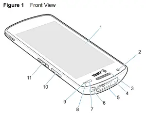
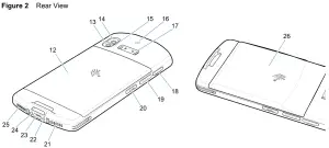
Device Features
| Item | Name | Description |
| 1 | Touch screen | Displays all information needed to operate the device. |
| 2 | Front camera | Takes photos and videos (available on some models). |
| 3 | Receiver | Use for audio playback in Handset mode. |
| 4 | Microphone | Use for communications in Speakerphone mode. |
| 5 | Exit window | Provides data capture using the imager (available on some models). |
| 6 | Power button | Turns the display on and off. Press and hold to reset the device or power off. |
| 7 | Proximity/Light sensor | Determines proximity for turning off display when in Handset mode.Determines ambient light for controlling display backlight intensity. |
| 8 | Data capture LED | Indicates data capture status. |
| 9 | Charging/Notification LED | Indicates battery charging status while charging and application generated notifications. |
| 10 | Scan button | Initiates data capture (programmable). |
| 11 | Volume Up/Down button | Increases and decreases audio volume (programmable). |
| Item | Name | Description |
| 12 | Standard battery | Provides standard battery capacity. |
| 13 | Camera flash | Provides illumination for the camera. |
| 14 | Rear camera | Takes photos and videos. |
| 15 | Microphone | Use for noise cancellation. |
| 16 | NFC antenna | Provides communication with other NFC-enabled devices. |
| 17 | Trigger handle mount | Provides electrical contacts (0, 2, or 8 pins) and mounting for the Trigger Handle. |
| 18 | SD/SIM card drawer | Provides access to micro SD card and SIM card. |
| 19 | Scan button | Initiates data capture (programmable). |
| 20 | Programmable Button | Typically used for PTT communications. Where regulatory restrictions exist1 button is configurable for use with other applications. |
| 21 | Microphone | Use for communications in handset mode. |
| 22 | Hand strap mount | Provides mounting point for hand strap and tether accessory. |
| 23 | USB-C connector | Provides USB host and client communications, and device charging via cables and accessories. |
| 24 | Charging connector | Provides device charging via cradles. |
| 25 | Speaker | Provides audio output for video and music playback. Provides audio in speakerphone mode. |
| 26 | Extended battery | Provides extended battery capacity. |
| 1 Pakistan, Qatar |
Setting Up the Device
To start using the device for the first time:
- Install a micro secure digital (SD) card (optional).
- Installing a nano SIM card (optional for EC55 only)
- Charge the device.
- Power on the device.
Installing or Replacing a microSD Card
The microSD card slot provides secondary non-volatile storage. For more information, refer to the documentation provided with the card and follow the manufacturer’s recommendations for use.![]() CAUTION: Follow proper electrostatic discharge (ESD) precautions to avoid damaging the microSD card. Proper ESD precautions include, but are not limited to, working on an ESD mat and ensuring that the operator is properly grounded.
CAUTION: Follow proper electrostatic discharge (ESD) precautions to avoid damaging the microSD card. Proper ESD precautions include, but are not limited to, working on an ESD mat and ensuring that the operator is properly grounded.
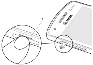
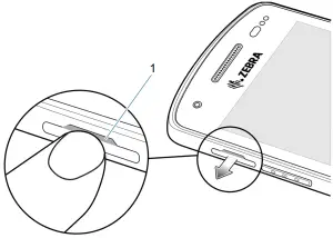
- Using your fingernail or a plastic tool, pull out the SD/SIM card drawer.
1 Fingernail or plastic tool access to SD/SIM card drawer 
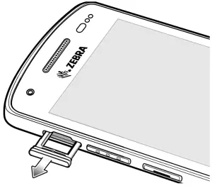
- Remove the SD/SIM card drawer from the device.
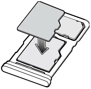
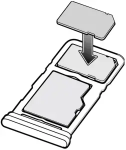
- Insert or replace the microSD card into the SD/SIM card drawer.
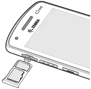
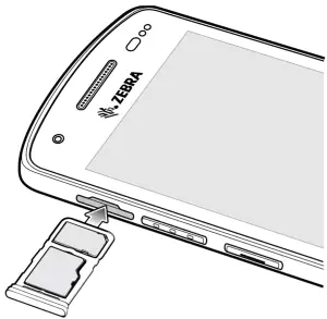
- Insert the SD/SIM card drawer into the device.
- Press the SD/SIM card drawer into the device to ensure it is in securely.
Installing or Replacing the SIM Card
![]() NOTE: Only use a nano SIM card. EC55 only.
NOTE: Only use a nano SIM card. EC55 only.![]() CAUTION: For proper electrostatic discharge (ESD) precautions to avoid damaging the SIM card. Proper ESD precautions include, but not limited to, working on an ESD mat and ensuring that the user is properly grounded.
CAUTION: For proper electrostatic discharge (ESD) precautions to avoid damaging the SIM card. Proper ESD precautions include, but not limited to, working on an ESD mat and ensuring that the user is properly grounded.
- Using your fingernail or a plastic tool, pull out the SD/SIM card drawer.
1 Fingernail or plastic tool access to SD/SIM card drawer - Remove the SD/SIM card drawer from the device.
- Insert the SIM card into the access drawer.
- Insert the microSD/SIM card access drawer into the device.
- Press the SD/SIM card drawer into the device to ensure it is in securely.

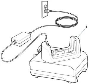
Device Charging
Before using the device for the first time, charge the device until the green Charging/Notification light emitting diode (LED) remains lit. To charge the device use a cable or a cradle with the appropriate power supply.The device’s Charging/Notification LED indicates the status of the device charging. See Table 1 Above for device charging status. When charging the device using a Zebra cradle or power supply, the standard battery charges from fully depleted to 90% in less than two hours. The extended battery charges from fully depleted to 90% in less than three hours.
![]() NOTE: In many cases the 90% charge provides plenty of charge for daily use.
NOTE: In many cases the 90% charge provides plenty of charge for daily use.
To achieve the best fast charging results use only Zebra charging accessories. Charge the device at room temperature.
Charging Indicators
Table 1 Charging/Notification LED Charging Indicators
| State | Indication |
| Off | Device is not charging. Device is not inserted correctly in the cradle or connected to a power source. Charger/cradle is not powered. |
| Slow blinking amber (1 blink every 4 seconds) | Device is charging. |
| Slow blinking red (1 blink every 4 seconds) | Device is charging but the battery is at end of useful life. |
| Solid green | Charging complete. |
| Solid red | Charging complete but the battery is at end of useful life. |
| Fast blinking amber (2 blinks/second) | Charging error, for example:
|
| Fast blinking red (2 blinks/second) | Charging error but the battery is at end of useful life., for example:
|
Charging Temperature
Charge batteries in temperatures from 5°C to 40°C (41°F to 104°F). The device or cradle always performs battery charging in a safe and intelligent manner. At higher temperatures (for example: approximately +37°C (+98°F)) the device or cradle may for small periods of time alternately enable and disable battery charging to keep the battery at acceptable temperatures. The device and cradle indicates when charging is disabled due to abnormal temperatures via its LED.
Charging the Device
Charge the device using a charging cradle or a charging cable. For information about the accessories available for the device, see Accessories. To charge the device using a charging cradle:
- Insert the device into a charging slot.
- Ensure the device is seated properly.
Accessories
![]() CAUTION: Ensure that you follow the guidelines for battery safety described in the device Product Reference Guide. Use one of the following accessories to charge the device.
CAUTION: Ensure that you follow the guidelines for battery safety described in the device Product Reference Guide. Use one of the following accessories to charge the device.
Table 2 Accessories
| Accessory | Part Number | Description |
| 1-Slot Charge Only Cradle | CRD-EC5X-1SCU-01 | Provides device charging only. Requires USB-C cable (CBL-TC5X-USBC2A-01) and power supply (PWR-WUA5V12W0xx). |
| 1-Slot USB/Ethernet Cradle | CRD-EC5X-1SCUE-01 | Provides device charging and communication. Requires power supply (PWR-BGA12V50W0WW) and DC line cord (CBL-DC-388A1-01). |
| 4-Slot Charge Only Cradle | CRD-EC5X-4SCO-01 | Charges up to four devices. Requires power supply (PWR-BGA12V108W0WW), DC line cord (CBL-DC-381A1-01), and country-specific AC line cord. |
| 4-Slot Charge Only Locking Cradle | CRD-EC5X-4SCOL-01 | Charges up to four devices. Requires power supply (PWR-BGA12V108W0WW), DC line cord (CBL-DC-381A1-01), and country-specific AC line cord. |
| 1-Slot Workstation Cradle | CRD-EC5X-1SWS-01 | Provides device charging, Ethernet communication, three 0.5 A USB ports, one 1.5 A USB port, and one HDMI port.Requires power supply(PWR-BGA12V50W0WW) and DC line cord (CBL-DC-388A1-01). |
| 5-Slot Ethernet Cradle | CRD-EC5X-SE5ET-01 | Provides up to five device charging, Ethernet Communication, and two Ethernet ports. Requires power supply(PWR-BGA12V108W0WW) and DC line cord (CBL-DC-381A1-01). |
| USB-C Communication and Charge Cable | CBL-TC5X-USBC2A-01 | Provides USB-A to USB-C communication and power to the device. |
1-Slot Charge Only Cradle
| 1 | Charging slot |
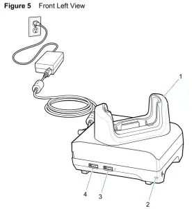
1-Slot USB/Ethernet Cradle
Figure 3 Front View
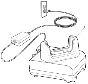
| 1 | Charging slot |
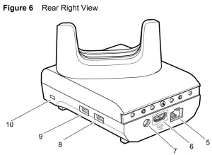
Figure 4 Back View
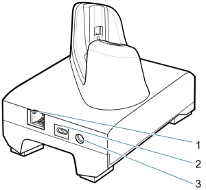
| 1 | RJ-45 port |
| 2 | USB-C port |
| 3 | DC power port |
4-Slot Charge Only Cradle
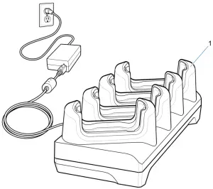
| 1 | Charging slot |
4-Slot Charge Only Locking Cradle
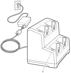
| Item | Name |
Description |
| 1 | Power LED | Indicates that power is applied to each cradle slot. |
1-Slot Workstation Cradle
|
Item |
Name |
Description |
| 1 | Charging slot | Holds the device during charging. |
| 2 | Power LED | Indicates that power is applied to the cradle. |
| 3 | 1.5 A USB port | USB Type A port for mouse or keyboard, or personal mobile device. |
| 4 | 0.5 A USB port | USB Type A port for mouse or keyboard. |
| Item | Name | Description |
| 5 | Ethernet port | Connects to an Ethernet network. |
| 6 | HDMI port | Connects to monitor. |
| 7 | Power port | Provides power to the cradle. |
| 8 | USB Type A port | Connection for mouse or keyboard. |
| 9 | USB Type A port | Connection for mouse or keyboard. |
| 10 | Kensington slot | Connecting point for Kensington locking system to secure cradle. |
5-Slot Ethernet Cradle
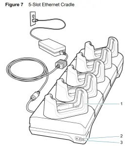
| Item | Name | Description |
| 1 | Charging slot | Holds the device during charging. |
| 2 | 1000 LED | Indicates 1 Gbps transfer rate. |
| 3 | 100/10 LED | Indicates 100 or 10 Mbps transfer rate. |
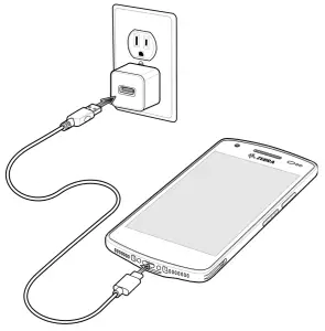
USB Communication and Charge Cable
The USB cable plugs into the bottom of the device. When attached to the device the cable allows charging, transferring data to a host computer, and connecting USB peripherals.
Scanning with Internal Imager
To read a barcode, a scan-enabled app is required. The device contains the Data Wedge app that allows the user to enable the imager, decode the barcode data, and display the barcode content. To scan with the internal imager:
- Ensure that an app is open on the device and a text field is in focus (text cursor in text field).
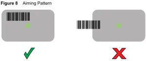
- Point the exit window on the top of the device at a barcode.
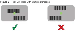
- Press and hold the scan button. The green aiming dot with white illumination turns on to assist in aiming. NOTE: When the device is in Picklist mode, the imager does not decode the barcode until the crosshair or aiming dot touches the barcode. 4. Ensure the barcode is within the area formed by the white illumination. The green aiming dot increases visibility in bright lighting conditions.
- The Data Capture LED lights green and a beep sounds, by default, to indicate the barcode was decoded successfully.
- Release the scan button. NOTE: Imager decoding usually occurs instantaneously. The device repeats the steps required to take a digital picture (image) of a poor or difficult barcode as long as the scan button remains pressed.
- The barcode content data displays in the text field.
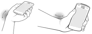
Ergonomic Considerations
![]() CAUTION: Avoid extreme wrist angles.
CAUTION: Avoid extreme wrist angles.
 report this ad
References
Zebra Open Source Terms | Zebra Technologies
Software Product Categories and End User License Agreements | Zebra
Copyright
Zebra Technologies | Visible. Connected. Optimized.
Software Product Categories and End User License Agreements | Zebra
Copyright
Zebra Open Source Terms | Zebra Technologies
Zebra Technologies | Visible. Connected. Optimized.
[xyz-ips snippet=”download-snippet”]