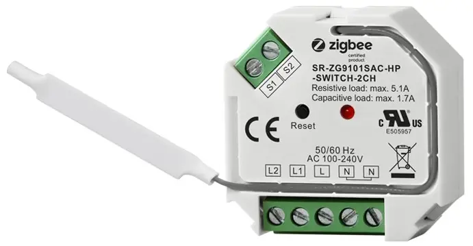
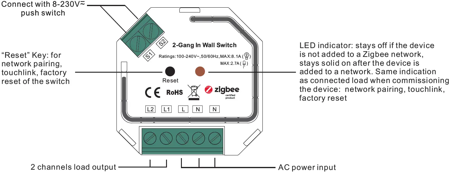
ZigBee 2-Gang In-wall Switch
Function Introduction
Product Data
|
Input Voltage |
Output Voltage | Output Channel | Max. Load | Size(LxWxH) |
| 100-240VAC | 100-240VAC | 2 Channels | Resistive load: max. 8.1A, capacitive load: max. 2.7A |
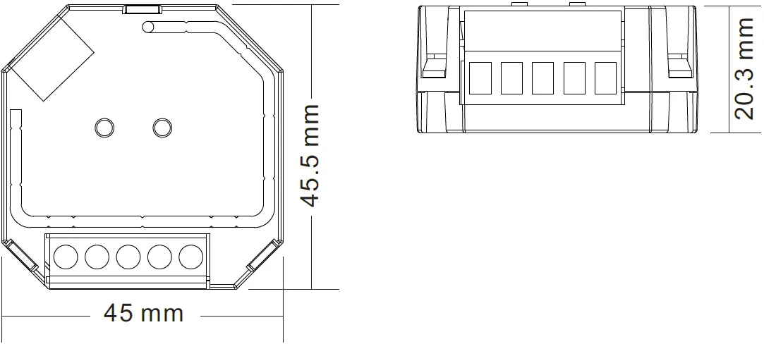
45.5x45x20.3mm |
|
Compatible Load Types |
|||
|
Load Symbol |
Load Type | Maximum Load |
Remarks |
| LED lamps with transformers | 620W @ 230V
290W @ 110V |
Due to variety of LED lamp designs, maximum number of LED lamps is further dependent on power factor result when connected to switch. | |
| LED drivers | 620W @ 230V
290W @ 110V |
Maximum permitted number of drivers is 620W divided by driver nameplate power rating. | |
| Incandescent lighting, HV Halogen lamps | 1860W @ 230V
890W @ 110V |
||
| Low voltage halogen lighting with electronic transformers | 620W @ 230V
290W @ 110V |
Over Current Protection
- When connecting resistive load and total load is over 1A, the relay will be forced to off and protected.
- 2-gang ZigBee in-wall switch based on latest ZigBee 3.0 protocol
- 100-240VAC wide input and output voltage
- Supports resistive loads and capacitive loads
- 2 channels output, max. load 8.1A total
- Input and output with screw terminals, safe and reliable
- Enables to control ON/OFF of connected load
- ZigBee device with 2 endpoints which can be controlled separately
- ZigBee end device that supports Touchlink commissioning
- Can directly pair to a compatible ZigBee remote via Touchlink without coordinator
- Supports self-forming zigbee network without coordinator and add other devices to the network
- Supports find and bind mode to bind a ZigBee remote
- Supports zigbee green power and can bind max. 20 zigbee green power switches
- Can be controlled by universal single wire push switch, 2 channels can be controlled separately by 2 switches
- Active power and energy metering functionality
- Mini Size, Easy to be installed into a standard wall box
- Radio Frequency : 2.4GHz
- Waterproof grade: IP20
Safety & Warnings
- DO NOT install with power applied to
- DO NOT expose the device to
ZigBee Clusters the device supports are as follows:
Input Clusters
- 0x0000: Basic 0x0003: Identify
- 0x0004: Groups
- 0x0005: Scenes
- 0x0006: On/off
- 0x0702: Simple Metering 0x0b04: Electrical Measurement
- 0x0b05: Diagnostics
Output Clusters
- 0x0019: OTA
Operation
- Do wiring according to connection diagram
- This ZigBee device is a wireless receiver that communicates with a variety of ZigBee compatible systems. This receiver receives and is controlled by wireless radio signals from the compatible ZigBee system.
- Zigbee Network Pairing through Coordinator or Hub (Added to a Zigbee Network)Step 1: Remove the device from previous zigbee network if it has already been added to, otherwise pairing will fail. Please refer to the part “Factory Reset Manually“.Step 2: From your ZigBee Controller or hub interface, choose to add lighting device and enter Pairing mode as instructed by the controller.

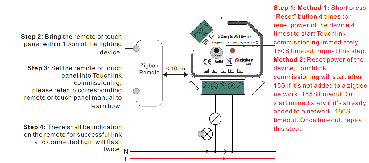
- TouchLink to a Zigbee RemoteNote:
- Directly TouchLink (both not added to a ZigBee network), each device can link with 1 remote.
- TouchLink after both added to a ZigBee network, each device can link with max. 30 remotes.
- To control by both gateway & remote, add remote and device to network first then TouchLink.
- After TouchLink, the device can be controlled by the linked remotes.
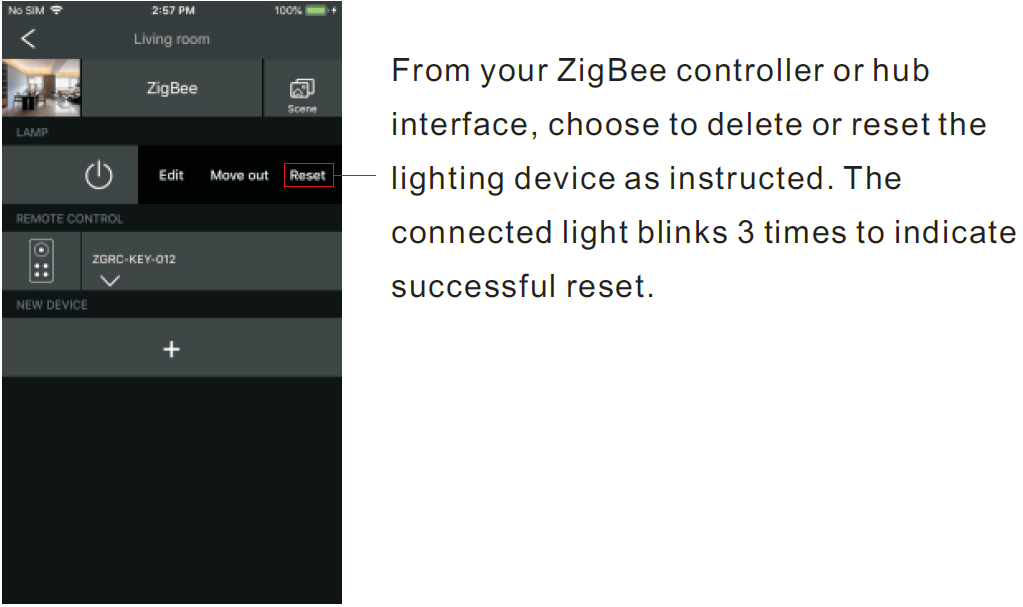
- Removed from a Zigbee Network through Coordinator or Hub Interface
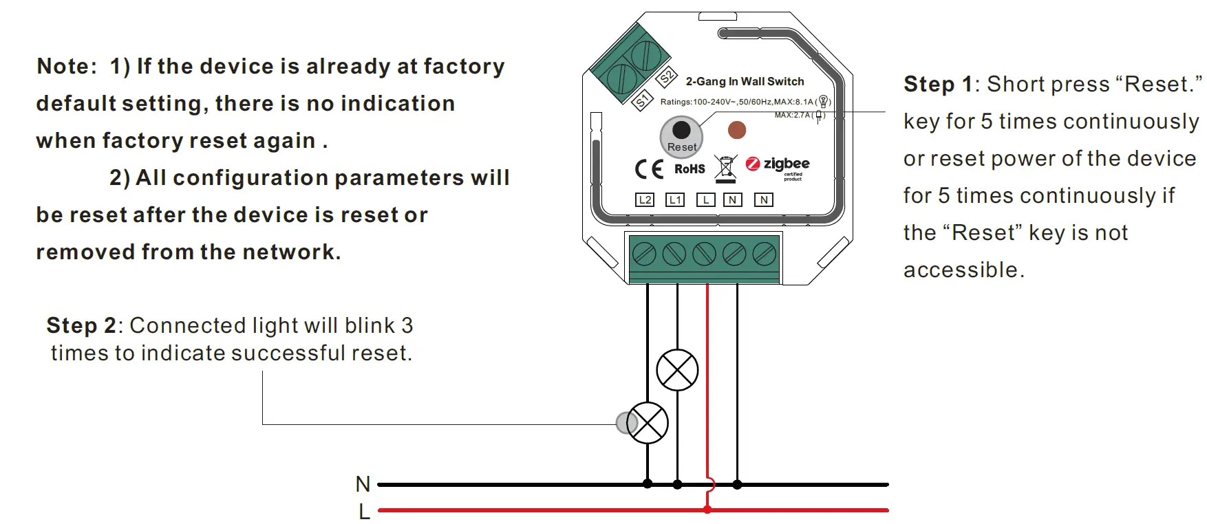
- Factory Reset Manually
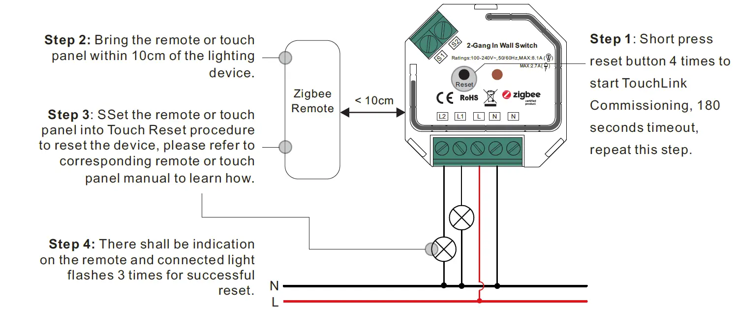
- Factory Reset through a Zigbee Remote (Touch Reset)Note: Make sure the device already added to a network, the remote added to the same one or not added to any network.
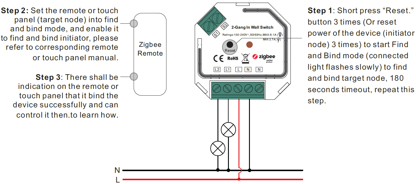
- Find and Bind ModeNote: Make sure the device and remote already added to the same zigbee network.
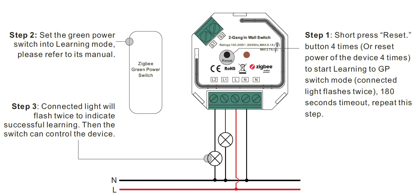
- Learning to a Zigbee Green Power SwitchNote: Each device can learn to max. 20 zigbee green power switches
- Delete Learning to a Zigbee Green Power Switch
- Setup a Zigbee Network & Add Other Devices to the Network (No Coordinator Required)Step 2: Set another device or remote or touch panel into network pairing mode and pair to the network, refer to their manuals.Step 3: Pair more devices and remotes to the network as you would like, refer to their manuals.Step 4: Bind the added devices and remotes through Touchlink so that the devices can be controlled by the remotes, refer to their manuals.Note:
- Each added device can link and be controlled by max. 30 added remotes.
- Each added remote can link and control max. 30 added devices.
- OTAThe device supports firmware updating through OTA, and will acquire new firmware from zigbee controller or hub every 10 minutes automatically.
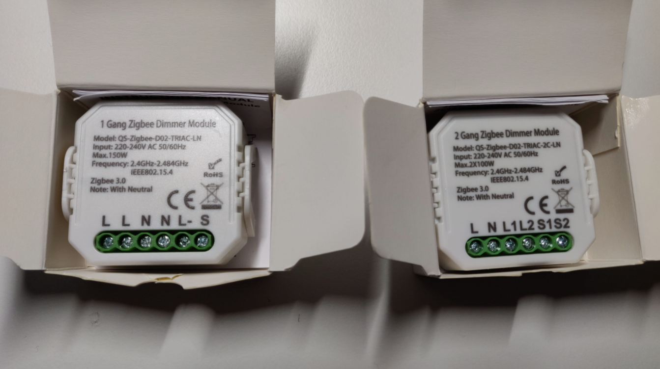
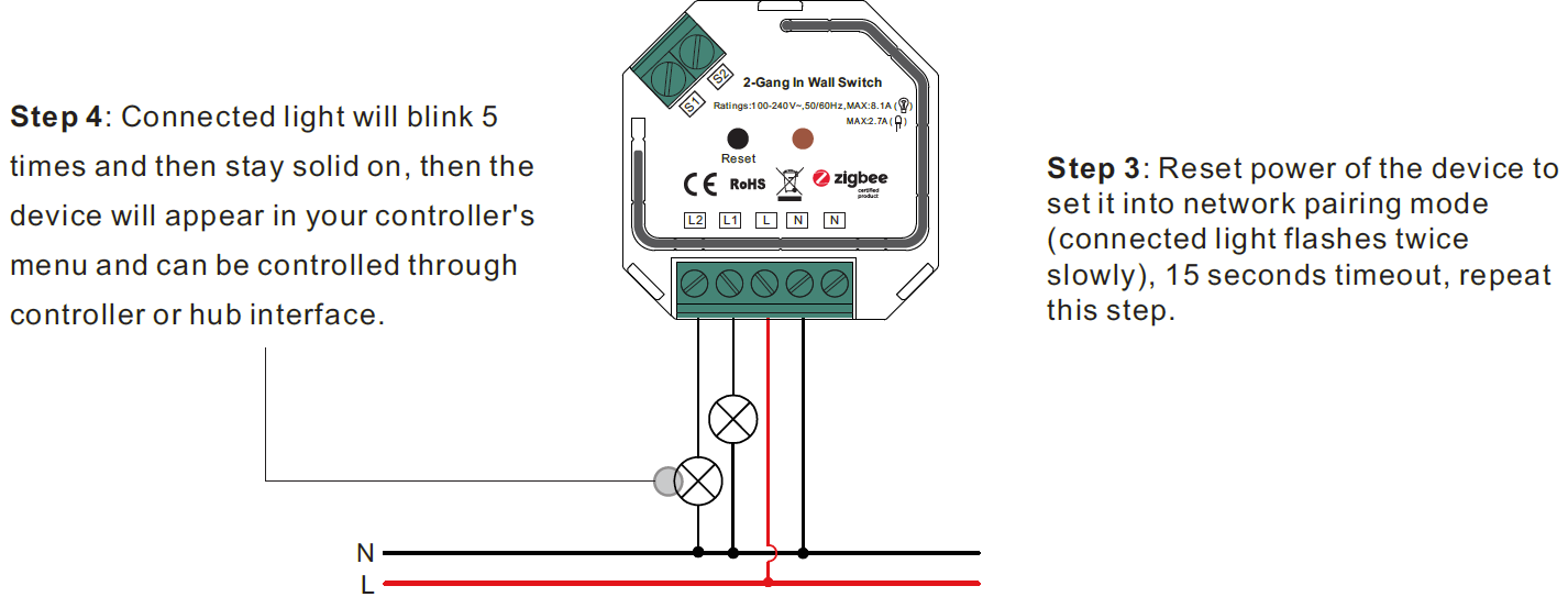
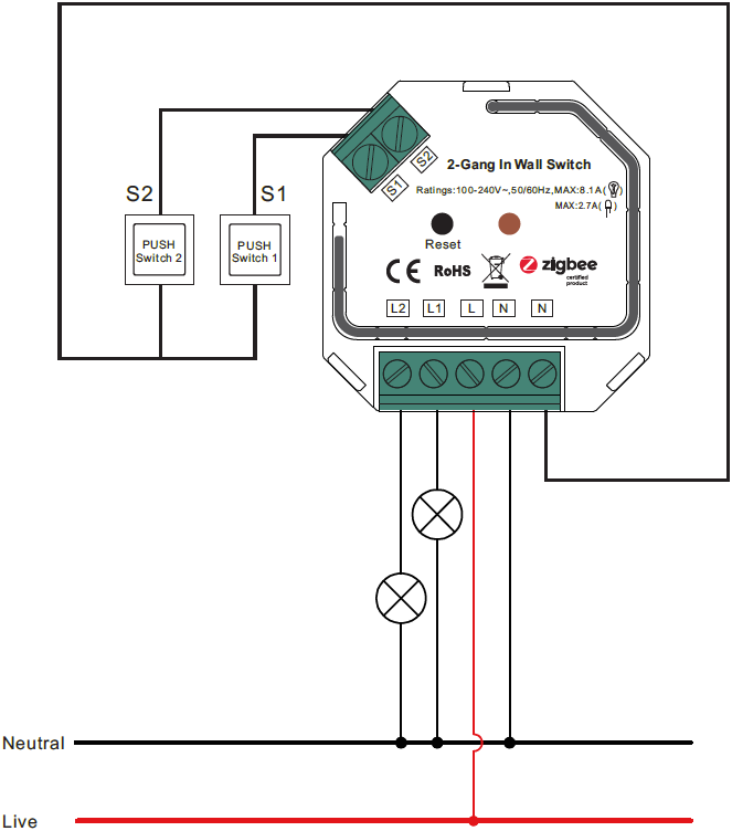
- Wiring DiagramNotes for the diagrams:L – terminal for live leadN – terminal for neutral leadS1 – terminal for switch key No. 1S2 – terminal for switch key No. 2L1 – output terminal no. 1 for light loadL2 – output terminal no. 2 for light load
 Note:
Note:
 Note: Each device can learn to max. 20 zigbee green power switches
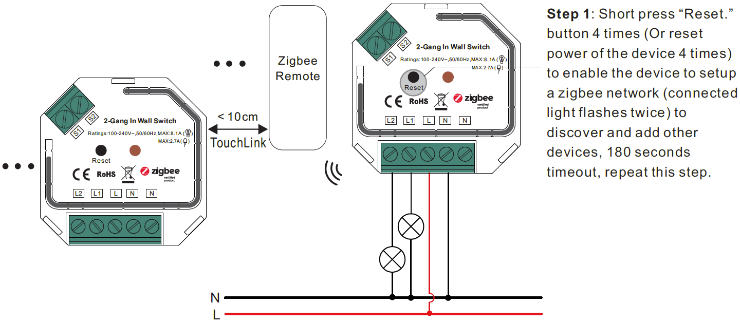
Product Dimension
![]()
[xyz-ips snippet=”download-snippet”]