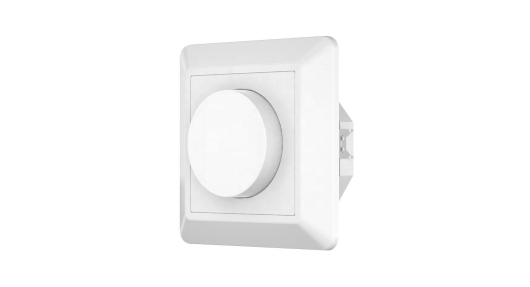
![]() ZigBee Knob Smart Dimmer
ZigBee Knob Smart Dimmer
Important: Read All Instructions Prior to Installation
Function introduction
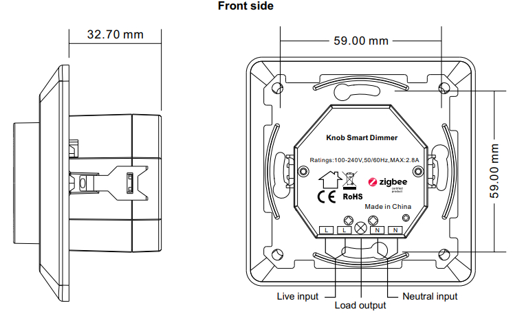
| Input Voltage | Output Voltage | Output Current | Size(LxWxH) |
| 100-240VAC | 100-240VAC | 2.8A max | 83.8×83.8×52.4mm |
| Compatible Load Types | |||
|
Load Symbol |
Load Type | Maximum Load |
Remarks |
|
Dimmable LED lamps |
300W @ 230V
150W @ 110V |
Due to the variety of LED lamp designs, a maximum number of LED lamps is further dependent on the power factor results when connected to dimmer. | |
| |
Dimmable LED drivers | 300W @ 230V
150W @ 110V |
The maximum permitted number of drivers is 300W divided by driver nameplate power rating. |
| Incandescent lighting, HV Halogen lamps | 600W @ 230V
300W @ 110V |
||
| Low voltage halogen lighting with electronic transformers | 300W @ 230V
150W @ 110V |
ZigBee Clusters the device supports are as follows:Input Clusters
| • 0x0000: Basic | • 0x0006: On/off |
| • 0x0003: Identify | • 0x0702: Simple Metering |
| • 0x0004: Groups | • 0x0008: Level Control |
| • 0x0005: Scenes | • 0x0b04: Electrical Measurement |
| • 0x0b05: Diagnostics |
Output Clusters
- 0x0019: OTA
- ZigBee knob smart dimmer based on latest ZigBee 3.0 protocol
- 100-240VAC wide input and output voltage can work under no neutral wiring and with neutral wiring, self-adaptive
- Supports resistive loads, capacitive loads, or inductive loads
- Enables to set minimum brightness and startup brightness
- 1 channel output, up to 600W
- Both leading edge version and trailing edge versions are available for choosing, preset by factory setting
- Enables to control ON/OFF and light intensity of the connected light source
- ZigBee end device that supports Touchlink commissioning
- Can be controlled by Zigbee gateway, Zigbee remote, and local rotary knob
- Can directly pair to a compatible ZigBee remote via Touchlink without a coordinator
- Supports self-forming ZigBee network without a coordinator and add other devices to the network
- Supports find and bind mode to bind a ZigBee remote
- Supports ZigBee green power and can bind max. 20 Zigbee green power remotes
- Compatible with universal ZigBee gateway products
- Standard size, can be compatible with existing EU standard frames, and installed into the standard size wall box
- Radio Frequency: 2.4GHz
- Waterproof grade: IP20
Main Features:
- Can operate under two-wire connection with no neutral lead or three-wire connection with neutral lead
- Advanced microprocessor control
- Implemented algorithm of smart light source detection
- Active power and energy metering functionality
- Soft-start function
- Innovative minimum dimming level and startup brightness setting functions
- A Bypass is an extension unit
As a dimmer it operates under the following loads:
- Conventional incandescent and HV halogen light sources
- ELV halogen lamps and dimmable LED bulbs (with electronic transformers)
- MLV halogen lamps (with ferromagnetic transformers)
- Dimmable LED bulbs
- Dimmable compact fluorescent CFL tube lamps
- Supported dimmable light sources (power factor > 0.5) with minimal power of 3VA using the Bypass (depending on the type of load)
Trailing edge or leading edge dimming mode can be preset by factory setting to control the following types of loads:
- “Trailing edge” for resistive loads
- “Trailing edge” for capacitive loads
- “Leading-edge” for inductive loads
Note: factory default version is trailing edge.
Safety & Warnings
- DO NOT install with power applied to the device.
- DO NOT expose the device to moisture.
Operation
- Do wiring according to the connection diagram correctly.
- This ZigBee device is a wireless receiver that communicates with a variety of ZigBee compatible systems. This receiver receives and is controlled by wireless radio signals from the compatible ZigBee system.
- Zigbee Network Pairing through Coordinator or Hub (Added to a Zigbee Network)Step 1: Remove the device from the previous Zigbee network if it has already been added to, otherwise pairing will fail. Please refer to the part “Factory Reset Manually”.Step 2: From your ZigBee Controller or hub interface, choose to add a lighting device and enter Pairing mode as instructed by the controller.

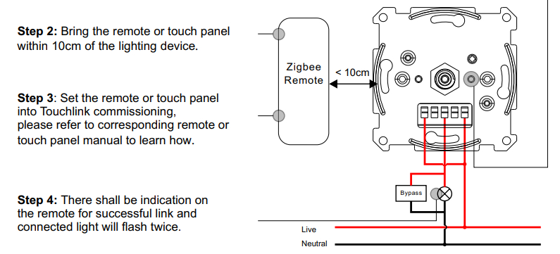
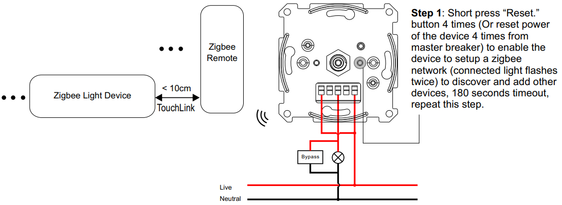
- TouchLink to a Zigbee RemoteStep 1: Method 1: Short press the “Reset” button 4 times (or reset the power of the device 4 times from the master breaker) to start Touch link commissioning immediately under any circumstances, 180S timeout, repeat this step.Method 2: Reset power of the device from the master breaker, Touchlink commissioning will start after 15S if it’s not added to a Zigbee network, 165S timeout. Or start immediately if it’s already added to a network, 180S timeout. Once timeout, repeat this step.Note:1) Directly TouchLink (both not added to a ZigBee network), each device can link with 1 remote.2) TouchLink after both are added to a ZigBee network, each device can link with max. 30 remotes.3) Control with both gateway and remote, add remote and device to the network first then TouchLink.4) After TouchLink, the device can be controlled by the linked remotes.
- Removed from a Zigbee Network through Coordinator or Hub Interface
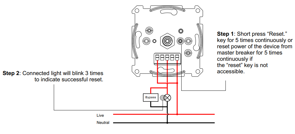
- Factory Reset Manually.Note:1) If the device is already at the factory default setting, there is no indication when the factory reset again.2) All configuration parameters will be reset after the device is reset or removed from the network.
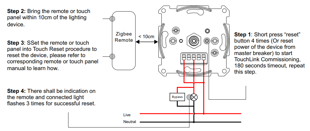
- Factory Reset through a Zigbee Remote (Touch Reset)Note: Make sure the device is already added to a network, the remote is added to the same one, or not added to any network.
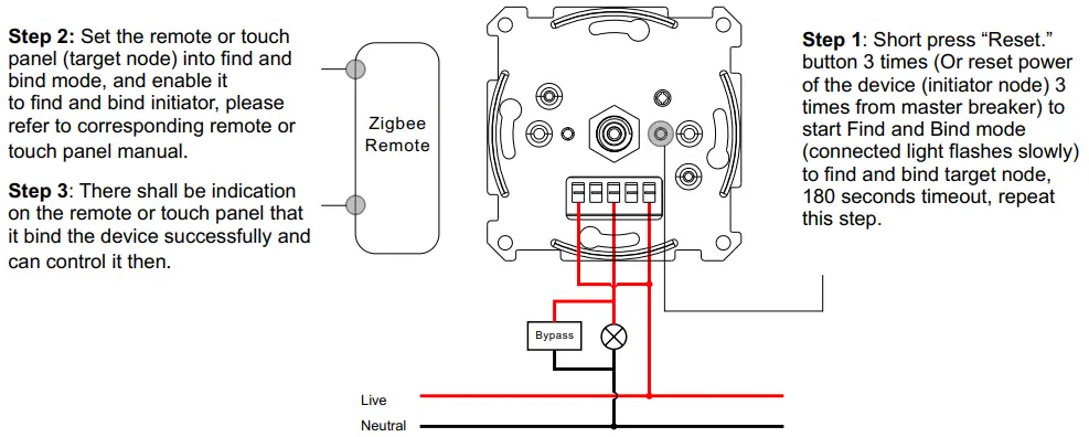
- Find and Bind ModeNote: Make sure the device and remote are already added to the same Zigbee network.
- Learning to a Zigbee Green Power RemoteNote: Each device can learn to the max. 20 Zigbee green power remotes.
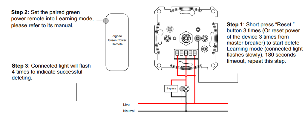
- Delete Learning to a Zigbee Green Power Remote
- Setup a Zigbee Network & Add Other Devices to the Network (No Coordinator Required)Step 2: Set another device or remote or touch panel into network pairing mode and pair to the network, refer to their manuals.Step 3: Pair more devices and remotes to the network as you would like, refer to their manuals.Step 4: Bind the added devices and remotes through Touchlink so that the devices can be controlled by the remotes, refer to their manuals.Note:1) Each added device can link and be controlled by max. 30 added remotes.2) Each added remote can link and control max. 30 added devices.
- OTAThe device supports firmware updating through OTA and will acquire new firmware from the Zigbee controller or hub every 10 minutes automatically.
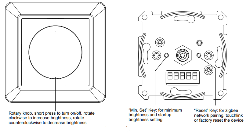
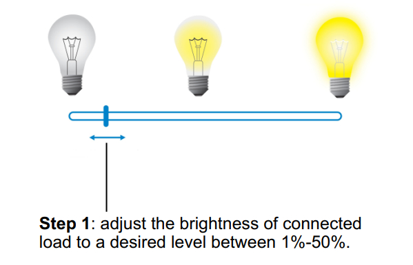
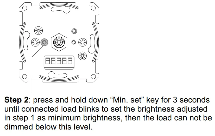
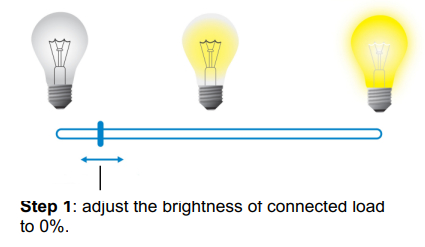
- Minimum Brightness Setting

 Note:1) Directly TouchLink (both not added to a ZigBee network), each device can link with 1 remote.2) TouchLink after both are added to a ZigBee network, each device can link with max. 30 remotes.3) Control with both gateway and remote, add remote and device to the network first then TouchLink.4) After TouchLink, the device can be controlled by the linked remotes.
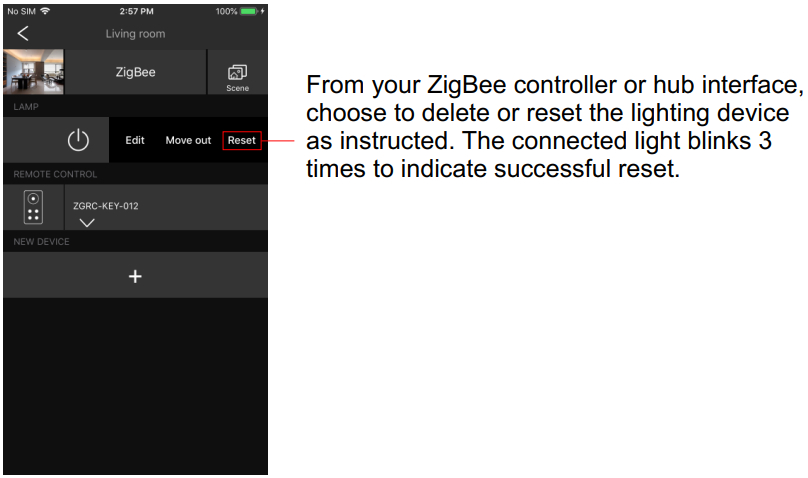
 Step 2: Set another device or remote or touch panel into network pairing mode and pair to the network, refer to their manuals.Step 3: Pair more devices and remotes to the network as you would like, refer to their manuals.Step 4: Bind the added devices and remotes through Touchlink so that the devices can be controlled by the remotes, refer to their manuals.Note:1) Each added device can link and be controlled by max. 30 added remotes.2) Each added remote can link and control max. 30 added devices.
Set Minimum Brightness
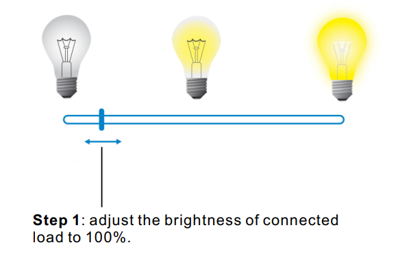
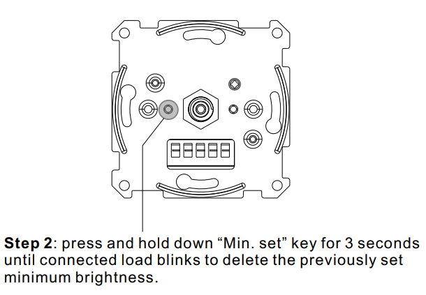
Delete Minimum Brightness
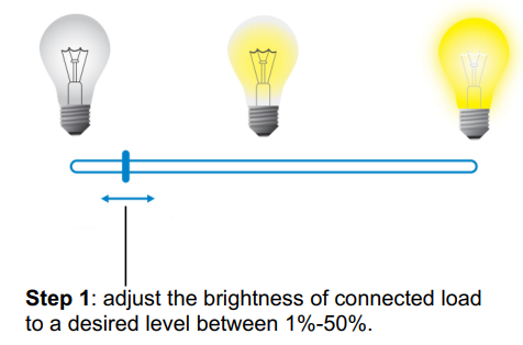
Startup Brightness Setting
Set Startup Brightness
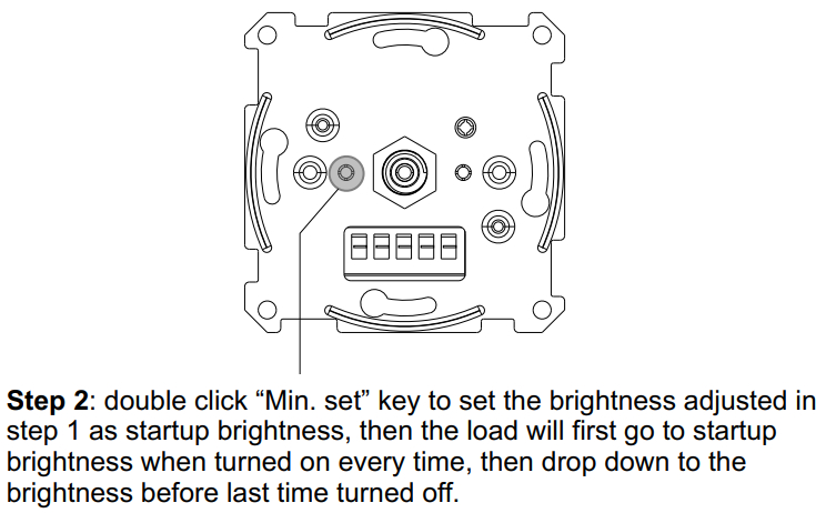 Note: startup brightness setting function is to avoid the phenomenon that some dimmable LED drivers can not be turned on after being turned off at a very low brightness level. Once setting a startup brightness, if the startup brightness is higher than the brightness before turned off, the driver will first go to the startup brightness after turned on then drop down to the level before turning off. If the startup brightness is lower than the brightness before turned off, the driver will directly go to the brightness before turning off.
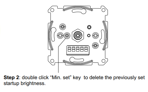
Delete Startup Brightness
Wiring Diagram
Notes for the diagrams:L – terminal for live leadN – terminal for neutral lead![]() – output terminal of the dimmer (controlling connected light source)
– output terminal of the dimmer (controlling connected light source)
Compatible load types and recommended values of power for supported loads:
|
Supported load types |
100-240V~ |
||
| Resistive loadsConventional incandescent and halogen light sources | 20-600W @ 230V20-300W @ 110V | ||
|
|
Capacitive loadsFluorescent tube lamp (compact / with electronic ballast), electronic transformer, LED | Using Bypass:3-300W @ 230V3-150W @ 110V | No Bypass Used: 20-300W @ 230V 20-150W @ 110V |
| Inductive loadsFerromagnetic transformers | 20-300W @ 230V20-150W @ 110V |
This phase dimmer adopts leading-edge dimming (forward phase control) or trailing edge dimming (reverse phase control), two versions are available for choosing, the factory default version is the trailing edge. Please make sure the connected loads support the control type you choose. Please refer to the user manual of the load or consult the supplier of the load.
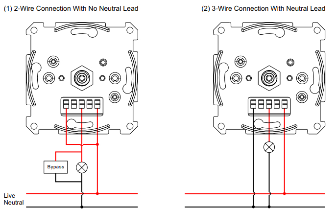
The Bypass is a device designed to work with the knob smart dimmer. It should be used in case of connecting LED bulbs or energy-saving compact fluorescent lamps. The Bypass prevents flickering of the LED lights and glowing of the turned-off compact fluorescent lamps. In the case of a 2-wire connection, the Bypass allows reducing the minimum power of load required by the dimmer for correct operation. The Bypass provides powering of the dimmer in case of controlling the low loads of minimum power down to 3W (for cosφ>0.5).
 report this ad
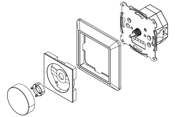
[xyz-ips snippet=”download-snippet”]