
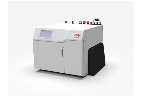
Zip HydroTap G5 Quick Start Installation Guide
Command CentreBoiling/Chilled models

Visit our website to download the manuals
SECTION 1: Using these instructions
Before you start

This document is a Quick Start Installation Guide.
For further details on installing and operating your HydroTap download & read the Command Centre installation and user instructions , which can be found online at:(Australia) www.zipwater.com(UK) specify.zipwater.co.uk

Read and use the instructions supplied with individual kit components for a safe installation.
Explanation of symbols

SECTION 2: IMPORTANT SAFETY INSTRUCTIONS
Compliance
In Australia electrical installation must comply with AS/NZS3000.
In Australia plumbing installation must comply with AS/NZS3500.
In Australia For residential chilled models, all refrigeration must comply with AS/NZS 60335.2.24.
In the UK the system must be installed in accordance with water supply byelaws, current IEE regulations and local authority byelaws.
Safety
This appliance is not intended for use by children under 8 years or persons (including children under 8 years) with reduced physical, sensory or mental capabilities, or lack of experience and knowledge, unless they have been given supervision or instruction concerning the use of the appliance by a person responsible for their safety. Children should be supervised to ensure that they do not play with the appliance.
Refrigerant

The Zip HydroTap Command Centre range uses either HIGHLY FLAMMABLE R290, R600a or R134A refrigerant under pressure. Check the rating plate or contact Zip before commencing work. Maintenance of the refrigeration unit must be carried out by an accredited service provider or qualified refrigeration technician. Keep ventilation openings, in the appliance enclosure or in the built-in structure, clear of obstruction.
Do not use mechanical devices or other means to accelerate the defrosting process, other than those recommended by the manufacturer.
Qualifications
To avoid hazards, all installation procedures must be carried out by a suitably qualified tradesperson. The power cable and power outlet must be in a safe visible position for connection.
Venting
Sometimes steam and / or boiling water droplets may discharge through a vent outlet on the tap. If not using the font, ensure the tap body is located so the tap outlet safely dispenses into the sink bowl.
Lifting
Take care when lifting. The Command Centre may exceed safe lifting limits. If you feel this is beyond your personal capabilities, please seek assistance with the lift. The weight of the Command Centre is marked on the packaging. Do not lift the Command Centre by the front cover or any of its connections.
Airflow
The Zip HydroTap operates within the ambient temperature range 5ºC – 35ºC. Proper air circulation must be provided. The system will operate satisfactorily only if the recommended air gaps are provided. The vent kit supplied must be fitted.
Altitude
Water boils at varying temperatures at different altitudes. The HydroTap adjusts for this during startup calibration and will recalibrate itself on a regular basis.
Frost protection
If the HydroTap is located where the ambient air temperature could fall below 5ºC when the system is not in use, do not turn off the Command Centre electrically. This safeguard does not offer the same protection to the connecting pipework and fittings.
SECTION 3: WARNINGS & REGULATORY INFORMATION

- For continued safety of this appliance it must be installed, operated and maintained in accordance with the manufacturer’s instructions.
- This appliance may deliver water at high temperature. Refer to the Plumbing Code of Australia (PCA), local requirements and installation instructions to determine if additional delivery temperature control is required.
 The Zip HydroTap must be earthed, earthing is provided via the supplied power cord. The resistance of the earth connection to each exposed metal part must be less than 1. Use the power cable supplied. It is the responsibility of the installer to ensure the power point is earthed.
- All installation and service work must be completed by trained and suitably qualified tradespeople. Faulty operation due to unqualified persons working on this product, may void warranty coverage.
- As the installer, it is your responsibility to supply and install all valves as required by local regulations and relevant standards.
- The HydroTap is rated for 220-240V 50Hz AC operation.
- Do not remove the cover of the appliance under any circumstances without first isolating the appliance from the power supply.
- Connect only to a potable (wholesome, cat1) mains water supply.
- Never locate the system near, or clean with water jets.
- Do not expose the Zip HydroTap to the elements of nature. The booster complies with protection class IP 20.
- For UK, a pressure limiting valve must be fitted for mains water pressures above the maximum limits stated.
- Use of tools can be hazardous. Assess the risks before you start.
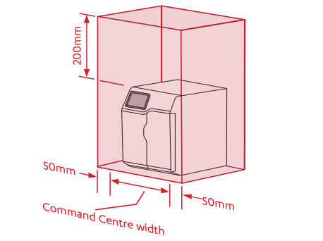
- A clearance envelope around all Command Centres must be provided to allow adequate ventilation for the safe and effective use of the HydroTap system.
- Valve and fitting threads must be sealed appropriately with PTFE tape where compression seals are not provided.
- Always flush new filter before use.
- Do not connect Booster to electrical supply until commissioning.
- Do not over tighten plumbing and hose connections.
- Braided hoses supplied cannot be lengthened.
- The power cord and general power outlet must be in a safe and accessible position after installation. When positioning the appliance, ensure the power supply cord is not trapped or damaged. If the power supply cord is damaged it must be replaced by a Zip service provider or a qualified electrician.
- Do not locate multiple portable socket-outlets or portable power supplies at the rear of the appliance.
- For safe operation, the HydroTap is designed to be installed, commissioned and used within 48 hours. Should the HydroTap not be required for an extended period of time (72 hours or more), do not fill and commission the HydroTap until ready for first use.
- For water taste and quality reasons, following any non-use period of more than 72 hours, Zip recommends to perform a system flush. Failure to flush the system may affect water quality.
- For UK, this appliance incorporates adequate backflow prevention in accordance to S.I.1999 No.1148 The Water Supply (Water fittings) Regulations 1999 Schedule 2 requirement. No further backflow prevention is required for connection to the water supply.
- For UK, this appliance only contains materials that conform to the requirements of BS6920:2014 `Suitability of non metallic materials and products for use in contact with water intended for human consumption with regard to their effect on the quality of water’.
SECTION 4: Technical data
| Model | Power ratingkW | DimensionsW x D x H (mm) | Weight (kg) |
| BC100BC100 H | 2.1 + 2.2* | 450 (500)# x 470 x 333 | 30 |
| BC60BC60 H | 2.1 | 450 (500)# x 470 x 333 | 30 |
| BC40BC40 H | 1.97 | 450 (500)# x 470 x 333 | 30 |
| BC30BC30 H | 1.9 + 2.2* | 280 x 470 x 333 | 23 |
| BC20BC20 H | 1.9 | 280 x 470 x 333 | 23 |
| BC Home | 1.44 | 280 x 470 x 333 | 30 |
* power rating of the booster #Including vent tray
Electricity supply requirements
220-240V 50Hz AC (for power requirement see table above).
| Without booster | With booster | |
| Australia | 1x 220 – 240V AC 10A socket | 2x 220 – 240V AC 10A sockets |
| UK | 1x 220 – 240V AC 13A socket | 2x 220 – 240V AC 13A sockets |
Water supply pressure requirements
| Component | Min – Max pressure, kPA (bar) | |
| Australia | UK | |
| HydroTap | 170 (1.7) – 700 (7.0) | 170 (1.7) – 500 (5.0) |
| Vented Mixer Tap | 300 (3.0) – 700 (7.0) | 200 (2.0) – 500 (5.0) |
| Booster | 200 (2.0) – 700 (7.0) | 200 (2.0) – 500 (5.0) |
| Limescale filter | 200 (2.0) – 700 (7.0) | 200 (2.0) – 500 (5.0) |
A pressure limiting valve must be fitted for mains water pressures above the maximum limits stated above in accordance with local plumbing regulations.
Note: All models (excluding UK) have an internal pressure limiting device to reduce the maximum mains regulated pressure (700kPa in Australia), protecting the system against pressure surges above 500kPa.
Water supply connection
1/2″ BSP (G1/2).
Booster specification
| Specification | Rating |
| Nominal power | 2.2kW |
| Nominal current | 10A |
| Flow rate | 1.2 L/m |
SECTION 5: Parts supplied
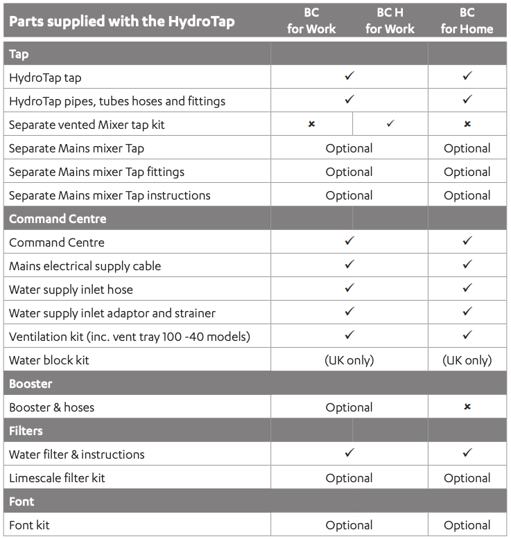
Note: Mains water isolation valve is not supplied with the kit.
Contact Zip for the full range of consumables and accessories.
SECTION 6: Set up the ventilation
Use of tools can be hazardous. Assess the risks before you start.
Use instructions supplied with individual kit parts.
A clearance envelope around all Command Centres must be provided to allow ventilation for the safe and effective use of the HydroTap system.
 BC100 – BC40 models
- Cold air is drawn in through the inlet vent and gap provided by the door buffers.
- Inlet vent is mounted over cupboard side, door or floor cut-out (see below).
- Warm air is exhausted through vent tray.
- Observe 100mm inlet / outlet vent separation (see below).
The vent tray must be fitted. It provides a safe exhaust for refrigerant gas in the unlikely event of a leak.
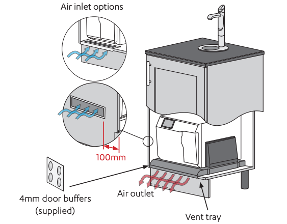
Vent tray dimensions WxDxH (mm): 500 x (515-555) x 40
BC30, BC20 & Home models
- Cold air is drawn in through the inlet vent and lower gap provided by the door buffers.
- Inlet vent is mounted over cupboard side, door or floor cut-out.
- Warm air is exhausted through upper gap provided by the door buffers.
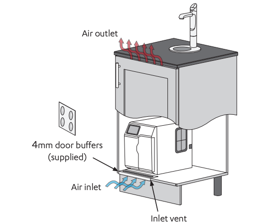
All models
If cupboard temperature exceeds 35°C, additional ventilation is required. Contact your Zip service provider for options (including additional vents and fan kit).
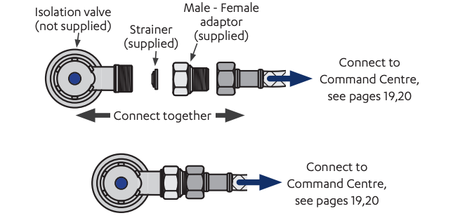
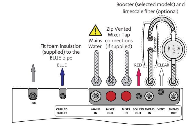
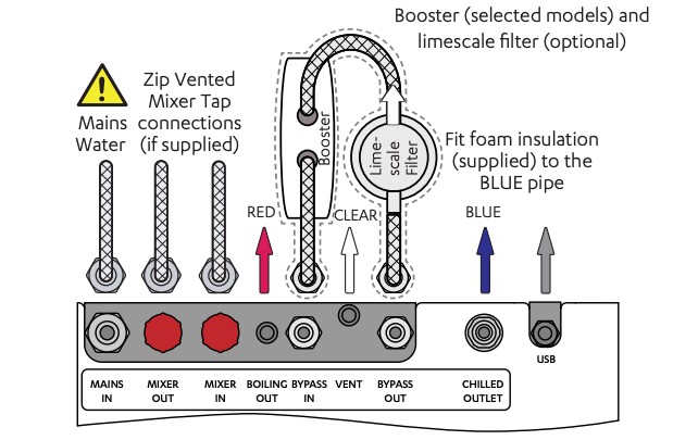
SECTION 7: Connect the water supply
Valves and fittings must be sealed with PTFE tape if compression seals are not included.
Note Mixer tap installations also use a `Tee piece’ as part of the water supply plumbing connections, see the Tap installation instructions supplied with the Mixer Tap to connect the water supply if using the mixer tap option.
Note correct strainer orientation.
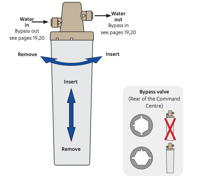
SECTION 8: Set the bypass & install the limescale filter
Available as optional accessory – UK only.
For filter head and scale filter installation use the guide supplied with the filter head and filter respectively.
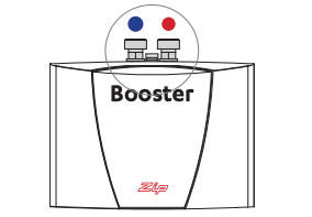
SECTION 9: Fit the Booster
- Supplied with selected models, or available as an optional accessory.
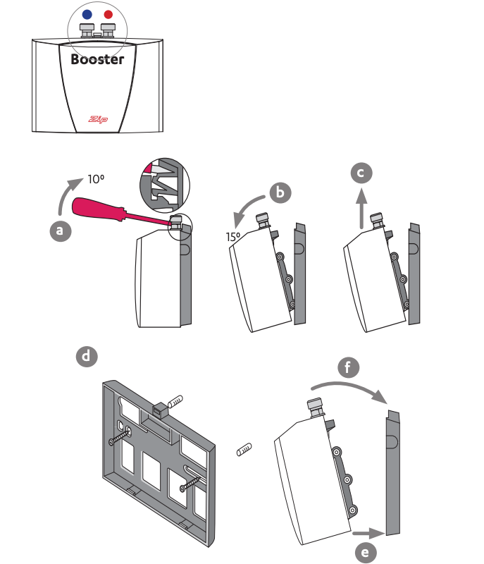
Note Take care not to break the clips when removing or installing the Booster.
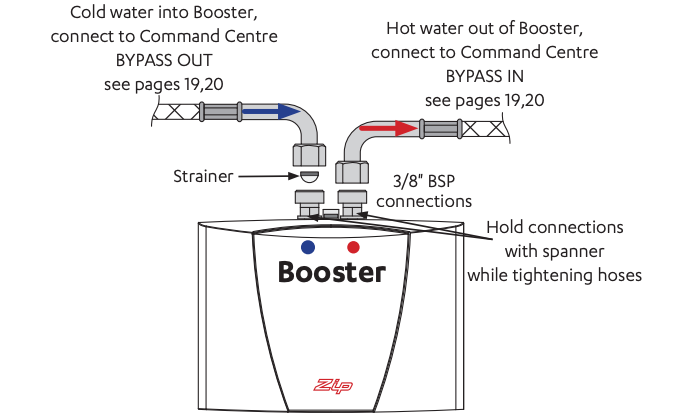
SECTION 10: Connect the Booster
Do not connect to electrical power until commissioning.
Do not over tighten hose connections.
Braided hoses supplied cannot be lengthened.
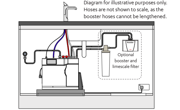
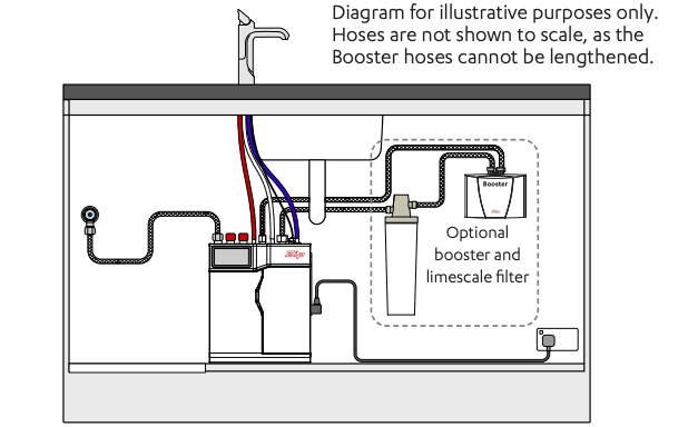
SECTION 11: Connect the Command Centre
Generic installation instructions
For HydroTap, mixer tap and any optional accessories, use instructions supplied with individual kit components.
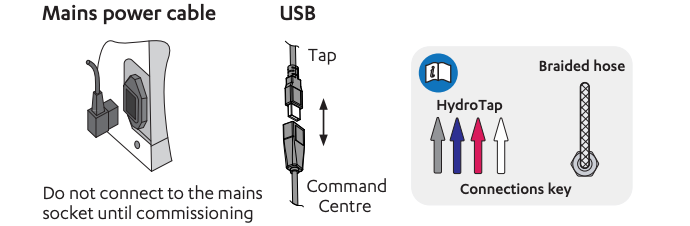
Installation diagrams are for illustrative purposes only. Hoses are not shown to scale and cannot be lengthened.
Tips for hose connection
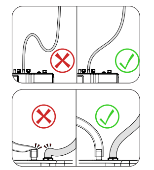
- Push the silicone hose over the connector for a minimum of 15mm.
- Ensure there a constant fall from the tap down to the command centre.
- Hoses must be trimmed to avoid loops and kinks. Take care when positioning before cutting and make a clean cut straight across the hose, using a sharp blade.
- The hoses must not be under tension when installed.
SECTION 11: Connect the Command Centre
BC40, BC60, BC100 models
Example installation
BC20, BC30, BC Home models
Example installation
SECTION 12: Commissioning

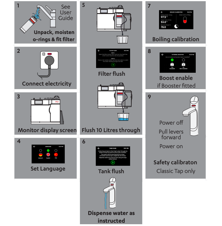
Notes
Refer to User Guide for operation and maintenance.
![]()
Zip Water (Australia) Pty Ltd
ABN 46 000 578 727 67 – 77Allingham Street, Condell Park NSW 2200Postal: Locked Bag 80, Bankstown 1885 AustraliaTel (+612) 9796 3100Free call 1800 947 827 (1800 ZIP TAP)www.zipwater.com

Zip Water UK
Trafalgar House, Rash’s Green,Dereham, Norfolk, NR19 1JG0345 6 005 005[email protected]specify.zipwater.co.uk
![]()
References
[xyz-ips snippet=”download-snippet”]