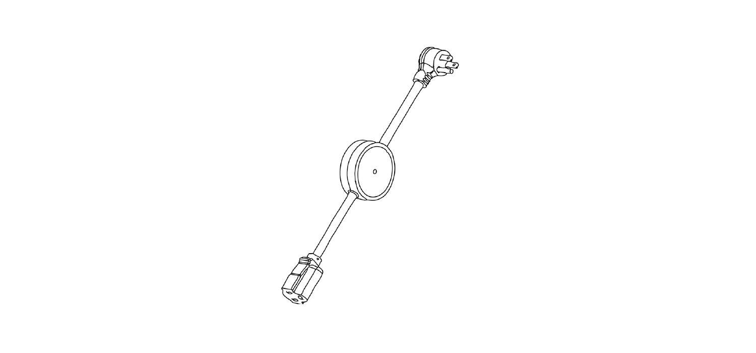
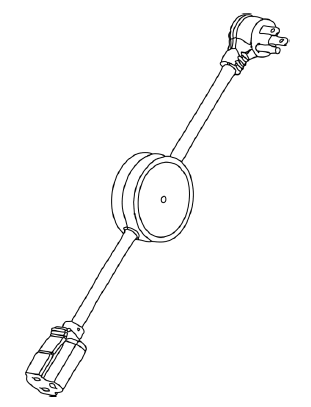
Z-Wave Power SwitchUser Manual
Model: ZEN15
FEATURES
- Local and Z-Wave wireless control of your favorite home appliances like microwaves and refrigerators
- Energy monitoring in live mode or over time (your Z-Wave gateway needs to support this feature)
- Scene inclusion for custom automation events when included to a Z-Wave gateway controller
- On/Off status recovery after power failure
- LED indicator to display Z-Wave signal strength and power usage for the connected device
- Added security with AES signal encryption (requires a security enabled gateway controller for full functionality)
- Z-Wave Plus with improved 500 chip for faster and more reliable wireless communication
- Built-in range extender
SPECIFICATIONS
- Model Number: ZEN15
- Z-Wave Signal Frequency: 908.42 MHz
- Power: 120V, 60Hz
- Maximum Load: 15A, 1800W, ½ HP
- Operating Temperature: 14° – 104° F
- Range: Up to 130 feet line of sight
- Installation and Use: Indoor only
- Dimensions: 20” (with cord) x 2.6” x 1.1”
- Weight: 10oz
Z-WAVE COMMAND CLASSES
This device requires the following command classes to be supported and recognized by your Z-Wave controller:
COMMAND_CLASS_ALLSWITCHCOMMAND_CLASS_ASSOCIATIONCOMMAND_CLASS_ASSOCIATION_GROUP_INFORMATIONCOMMAND_CLASS_BASICCOMMAND_CLASS_CONFIGURATIONCOMMAND_CLASS_DEVICE_RESET_LOCALCOMMAND_CLASS_FIRMWARE_UPDATE_MDCOMMAND_CLASS_MANUFACTURER_SPECIFICCOMMAND_CLASS_METERCOMMAND_CLASS_POWERLEVELCOMMAND_CLASS_SCENE_ACTIVATIONCOMMAND_CLASS_SCENE_ACTUATOR_CONFIGURATIONCOMMAND_CLASS_SECURITYCOMMAND_CLASS_SWITCH_BINARYCOMMAND_CLASS_VERSIONCOMMAND_CLASS_ZWAVEPLUS_INFO
BEFORE YOU RETURN IT
Let us know if you are having any issues installing or operating the device.Our fast and friendly tech support is here to help, every day of the year: Get more helpful tips at getzooz.com
INSTALLATION: PLEASE READ
WAIT!Make sure the load you are about to connect does not exceed 1800W, 15A, or 1/2 HP in power.DO NOT CONNECT THIS SWITCH TO 220V APPLIANCES.
Connecting heavy duty equipment powered by 220V to this Power Switch will DAMAGE the device and may cause the connected appliance to malfunction.
DO NOT connect any of the following to this Power Switch:
- 220V water boilers
- Electrical dryers
- 220V compressors or pumps
- Phone or battery chargers
- Electric heaters
You may safely use this smart plug with:
- 110V refrigerators rated at or below 15A
- 110V window and split AC units rated at or below 15A
- 110V Humidifiers and dehumidifiers
- 110V Sump pumps and other pumps rated at or below 1/2HP
- Microwaves
- Gas dryers
- Floor lamps
- TV’s and Audio / Video Equipment
- Computers / PCs / Laptops
- Alarm Clocks
Not sure if your equipment can be safely controlled by the Power Switch?
Just ask:
Plug the Power Switch into any standard grounded 110V receptacle. Do NOT connect any devices to the plug at this point. Press and release the Z-Wave button and make sure the LED indicator goes on as well – this confirms the surge protector is active.
Q: I pressed the Z-Wave button but the LED did not light up. What should I do?A: If you just purchased your device and the LED indicator never turned on, please try plugging the device into a different receptacle to verify it’s not a grounding issue and try pressing the Z-Wave button a few times quickly. If the LED still does not turn on, contact the reseller or Zooz directly:
Use the Z-Wave button to turn the lamp or appliance on and off manually. The plug is off when the LED indicator is lit up in pink.
WIRELESS CONTROL

Please include the Power Switch to your network BEFORE connecting it to the appliance you wish to control.Auto Z-Wave Inclusion
- Put your Z-Wave controller into inclusion mode
- Plug the Power Switch into a grounded receptacle located within direct range from your Z-Wave gateway controller
- The LED indicator will start flashing blue, then turn blue (on) or pink (off) once included
- A new on / off device will be recognized by your Z-Wave controller
Manual Z-Wave Inclusion
- Plug the Power Switch into a grounded receptacle located within direct range from your Z-Wave gateway controller
- Put your Z-Wave controller into inclusion mode
- Press and release the Z-Wave button 3 TIMES QUICKLY
- The LED indicator will start flashing blue, then turn blue (on) or pink (off) once included
- A new on / off device will be recognized by your Z-Wave controller
Secure Z-Wave Inclusion
- Plug the Power Switch into a grounded receptacle located within direct range from your Z-Wave gateway controller
- Put your Z-Wave controller in secure inclusion mode
- Press and HOLD the Z-Wave button for at least 3 seconds
- The LED indicator will start flashing green, then turn blue (on) or pink (off) once included
- A new secure on / off device will be recognized by your Z-Wave controller
TROUBLESHOOTING TIPS:
If you are unable to include the Z-Wave Power Switch to your controller, please try one of the following:
- Bring the Power Switch closer to your Z-Wave controller
- Once you put the controller into inclusion mode, press and release the Z-Wave button quickly more than 3 times to ensure the command has gone through
- Put your controller into EXCLUSION mode. Press and release the Z-Wave button quickly 3 times, and then try adding it to your network again
- If you are trying to include the Power Switch as a secure device, please make sure your controller supports AES signal encryption
Z-WAVE EXCLUSION
- Plug the Power Switch into a grounded receptacle located within direct range of your Z-Wave gateway controller
- Put your Z-Wave controller into exclusion mode
- Press and release the Z-Wave button 3 TIMES QUICKLY
- The LED indicator will start flashing orange, then turn blue (on) or pink (off) once excluded
- The Power Switch will disappear from your controller’s device list. The LED indicator will remain solid orange for a few seconds to indicate exclusion
If the first attempt is unsuccessful, please repeat the process following all steps carefully.
FACTORY RESET
When your network’s primary controller is missing or otherwise inoperable, you may need to reset the device to factory settings manually. In order to complete the process, plug the Power Switch into a grounded receptacle, then PRESS AND HOLD the Z-Wave button for AT LEAST 20 SECONDS. The LED indicator will flash orange and then stay solid orange for 2 seconds to indicate successful reset. The Power Switch will then turn off.
NOTE: All previously recorded activity and custom settings will be erased from the device’s memory. You may only reset your Power Switch once it has been in-cluded to a Z-Wave network.
ASSOCIATION
Depending on your Z-Wave gateway’s home automation software capabilities, you may be able to associate your Power Switch in groups with other Z-Wave devices to schedule scenes and create events. This Power Switch supports Group 1 with up to five devices for lifeline communication. This device will send BASIC REPORT to Group 1 when operated manually.
LED NOTIFICATIONS
The LED indicator on your Power Switch will visually report power consumption and network range.
How to read LED indicator colors?
Pink = Power Switch is offBlue = 0 – 300 WCyan = 300 – 600 WGreen = 600 – 900 WYellow = 900 – 1200 WRed = 1200 – 1500 WPurple = 1500 – 1800 WPurple blink = over 1800 W
LED Indicator Control
Parameter 27: You can choose how the LED indicator displays power consumption on the Power Switch
Values: 0 – LED indicator will display power consumption whenever the device is plugged in (LED stays on at all times – default setting); 1 – LED indicator will display the level of power consumption for 5 seconds only whenever the device is turned on or off (LED indicator will stay off for most of the time).
Size: 1 byte dec.
How to test Z-Wave network range for my Power Switch?You can easily check if the Power Switch is within your Z-Wave controller’s range:Press and hold the Z-Wave button for 6 to 9 seconds until the LED indicator turns violet. The LED indicator will then report signal strength.
- Flashing green = direct communication with the primary controller is established and still being diagnosed
- Solid green for 2 seconds = direct communication with the primary controller is stable
- Flashing orange = direct communication with the primary controller is intermittent and being diagnosed
- Solid orange = communication quality is fair
- Solid red = communication with the primary controller has failed
Press and release the Z-Wave button to exit testing mode.
This function may only be activated once the Power Switch has been included to a Z-Wave network.
ADVANCED SETTINGS
If your controller’s software allows for advanced configuration and parameter adjustment, you will be able to change and save the settings below and customize the Power Switch to serve your needs. Please refer to your controller’s user guide for advanced programming instructions as they are a little different for each software.
Overload Protection
Parameter 20: Overload protection will turn the Power Switch relay off once power exceeds 16.5A for over 5 seconds when this setting is enabled. We DO NOT recommend changing this parameter’s value as it may result in device damage and malfunction.
Values: 0 – Disabled; 1 – Enabled (default).
Size: 1 byte dec.
On/Off Status Recovery After Power Failure
Parameter 21: Choose the recovery state for your Power Switch if power outage occurs.
Values: 0 – Power Switch remembers the status prior to power outage and turns back to it (default); 1 – Power Switch automatically turns ON once power is restored (it does not remember the status prior to power outage); 2 – Power Switch automatically turns OFF once power is restored (it does not remember the status prior to power outage);
Size: 1 byte dec.
On/Off Status Change Notifications
Parameter 24: Your Power Switch will automatically send a notification to the controller and other associated devices if its status changes from on to off or the other way round. Choose when you want it to send the report.
Values: 0 – disabled (it will not send status change notifications); 1 – sends notification if status is changed manually or remotely via Z-Wave (default); 2 – sends notification ONLY if status is changed manually by pressing and releasing the Z-Wave button on the Power Switch;
Size: 1 byte dec.
Power Report Value Threshold
Parameter 151: Choose how you want your Power Switch to report power consumption to your controller and associated devices. The number entered as value corresponds to the number of Watts the appliance needs to go over for the change to be reported. So if 50 Watts are entered by default, the Power Switch will report any change in power usage over 50 Watts (whether it’s at least 50 Watts more or 50 Watts less compared to previous report).
Values: 0 – 65535; 0 – disabled (it will not report power consumption based on value change); 50 – default setting
Size: 2 byte dec.
Power Report Percentage Threshold
Parameter 152: Choose how you want your Power Switch to report power consumption to your controller and associated devices by percentage rate. The number entered as value corresponds to the percentage in power usage change the appliance needs to go over for the event to be reported. So if 10% is entered by default, the Power Switch will report any change in power consumption over 10% (whether it’s at least 10% more or 10% less power consumption compared to previous report).
Values: 0 – 255; 0 – disabled (it will not report power consumption based on percentage change); 10 – default setting
Size: 1 byte dec.
Power Report Frequency
Parameter 171: Choose how often you want your Power Switch to report power consumption (W) to your controller and associated device. The number entered as value corresponds to the number of seconds. So if 30 is entered by default, the Power Switch will report power consumption every 30 seconds.
Values: 5 – 2678400; 0 – disabled (it will not report power consumption); 30 – default setting
Size: 4 byte dec.
Energy Report Frequency
Parameter 172: Choose how often you want your Power Switch to report energy usage (KWH) to your controller and associated device. The number entered as value corresponds to the number of seconds. So if 300 is entered by default, the Power Switch will report energy usage every 300 seconds (5 minutes).
Values: 5 – 2678400; 0 – disabled (it will not report energy usage); 300 – default setting
Size: 4 byte dec.
Voltage Report Frequency
Parameter 173: Choose how often you want your Power Switch to report voltage (V) to your controller and associated device. The number entered as value corresponds to the number of seconds.
Values: 5 – 2678400; 0 – disabled (default – it will not report voltage levels)
Size: 4 byte dec.
Electricity Report Frequency
Parameter 174: Choose how often you want your Power Switch to report levels of electrical current (A) to your controller and associated device. The number entered as value corresponds to the number of seconds.
Values: 5 – 2678400; 0 – disabled (default – it will not report electrical current levels)Size: 4 byte dec.
WARNING
- This product should be installed indoors upon completion of any building renovations
- Prior to installation, the device should be stored in a dry, dust-and-mold-proof place
- Do not install the Power Switch in a place with direct sun exposure, high temperature or humidity
- Keep away from chemicals, water, and dust
- Ensure the device is never close to any heat source or open flame to prevent fire
- Ensure the device is connected to an electric power source that does not exceed the maximum load power
- No part of the device may be replaced or repaired by the user
Z-WAVE PLUS CERTIFIED
This product can be included and operated in any Z-Wave network with other Z-Wave certified devices from other manufacturers and/or other applications. All non-battery operated nodes within the network will act as repeaters regardless of vendor to increase reliability of the network.
ETL CERTIFIED
This is an ETL certified device. ETL, just like UL, is a Nationally Recognized Testing Laboratory. The ETL mark is proof of product compliance to North American safety standards.
WARRANTY
This Limited Warranty applies to physical goods, and only for physical goods, purchased from Zooz (the “Physical Goods”).
What does this limited warranty cover?This Limited Warranty covers any defects in material or workmanship under normal use according to instructions from the User Manual during the Warranty Period. Warranty coverage applies to purchases made from authorized dealers only. See full list of Zooz distributors here: getzooz.com/buyDuring the Warranty Period, Zooz will repair or replace, at no charge, products or parts of a product that prove defective because of improper material or workmanship, under normal use and recommended maintenance. Zooz does not assume the cost of return shipping for warranty service.
How long does the coverage last?The Warranty Period for Physical Goods purchased from Zooz is 12 months from the date you purchased this product.
What does this limited warranty not cover?This Limited Warranty does not cover any problem that is caused by:
- Conditions, malfunctions or damage not resulting from defects in material or workmanship
- improper handling or installation of the product
The warranty does not cover purchases from unauthorized dealers or second-hand sources.The warranty does not cover return shipping cost for warranty service.
What do you have to do?To obtain warranty service, please contact us to determine the problem and offer a quick solution for you: You may also get in touch with the reseller of the product directly to return or replace the product within 30 days of purchase or within applicable reseller’s returns period.
IN NO EVENT SHALL ZOOZ OR ITS SUBSIDIARIES AND AFFILIATES BE LIABLE FOR ANY INDIRECT, INCIDENTAL, PUNITIVE, SPECIAL, OR CONSEQUENTIAL DAMAGES, OR DAMAGES FOR LOSS OF PROFITS, REVENUE, OR USE INCURRED BY CUSTOMER OR ANY THIRD PARTY, WHE-THER IN AN ACTION IN CONTRACT, OR OTHERWISE EVEN IF ADVISED OF THE POSSIBILITY OF SUCH DA-MAGES. ZOOZ’S LIABILITY AND CUSTOMER’S EXCLUSIVE REMEDY FOR ANY CAUSE OF ACTION ARISING IN CON-NECTION WITH THIS AGREEMENT OR THE SALE OR USE OF THE PRODUCTS, WHETHER BASED ON NEGLIGENCE, STRICT LIABILITY, BREACH OF WARRANTY, BREACH OF AGREEMENT, OR EQUITABLE PRINCIPLES, IS EXPRESSLY LIMITED TO, AT ZOOZ’S OPTION, REPLACEMENT OF, OR REPAYMENT OF THE PURCHASE PRICE FOR THAT POR-TION OF PRODUCTS WITH RESPECT TO WHICH DA-MAGES ARE CLAIMED. ALL CLAIMS OF ANY KIND ARISING
IN CONNECTION WITH THIS AGREEMENT OR THE SALE OR USE OF PRODUCTS SHALL BE DEEMED WAIVED UNLESS MADE IN WRITING WITHIN THIRTY (30) DAYS FROM ZOOZ’S DELIVERY, OR THE DATE FIXED FOR DELI-VERY IN THE EVENT OF NONDELIVERY.
FCC NOTE
THE MANUFACTURER IS NOT RESPONSIBLE FOR ANY RADIO OR TV INTERFERENCE CAUSED BY UNAUTHORIZED MODIFICATIONS TO THIS EQUIPMENT. SUCH MODIFICATIONS COULD VOID THE USER’S AUTHORITY TO OPERATE THE EQUIPMENT. STORE INDOORS WHEN NOT IN USE. SUITABLE FOR DRY LOCATIONS ONLY. DO NOT IMMERSE IN WATER. NOT FOR USE WHERE DIRECTLY EXPOSED TO WATER.
This device complies with Part 15 of the FCC Rules.Operation is subject to the following conditions:
- This device may not cause harmful interference,
- This device must accept any interference received, including interference that may cause undesired operation.
This equipment has been tested and found to comply with the limits for a Class B digital device, pursuant to part 15 of the FCC Rules.
These limits are designed to provide reasonable protection against harmful interference in a residential installation.This equipment generates, uses and can radiate radio frequency energy and, if not installed and used according to instructions, may cause harmful interference to radio communications.
However, there is no guarantee that interference will not occur in any given installation.If this equipment causes harmful interference to radio or television reception, the user may try to correct the interference by taking one or more of the following measures:
- Reorient or relocate receiving antenna
- Increase the separation between equipment and receiver
- Connect equipment into a separate outlet or circuit from receiver
- Consult the dealer or an experienced radio/TV technician for additional assistance
All brand names displayed are trademarks of their respective holders.© Zooz 2017
References
[xyz-ips snippet=”download-snippet”]