
ZWP Wall Light Switch User Manual
INTRODUCTION
Z-Wave Products WS-100 is a member of the Z-Wave family and communicates with other Z-Wave certified devices in a control network. WS-100 replaces a standard in-wall light switch and turns it into a Z-Wave controlled network device. Each Z-Wave device serves as a node to repeat the signal in the network, thus, extending the overall Z-Wave mesh wireless network range. Different types and brands of Z-Wave devices can be associated with Z-Wave Products in your system and they will work together to optimize and expand the coverage of your Z-Wave network. Once setup is completed, you can enjoy the convenience and leisure which WS-100 offers.
FEATURES
- Works with incandescent, florescent (CIL), or LED lighting and appliance
- ON/OFF status and location LED indicator
- Scene control capable
- Instantly reports manual status change to controller
- Over We air :OTA) firmware upgrade avatahle with controllers/gateways that supports OTA
- Z-Wave Plus certified
- Z-Wave 500 Series module inside
- Fits standard single wall plate
- Fits standard multiple gang junction box
!WARNING !
RISK OF FIRE, ELECTRICAL SHOCK & BURNS DO NOT USE WITH MEDICAL AND LIFE SUPPORT INS I RUMENT No user serviceable parts are in this module The appliance connected to WS-100 must not exceed 900W incandescent, 200W CF/LED, 1/2 horsepower motor and 15A, 1800W resistive load.
Setup
This device require neutral wire
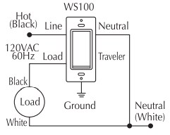
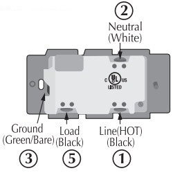
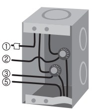
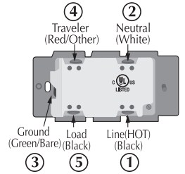
Step 1 :Identifying the wiring terminal on the module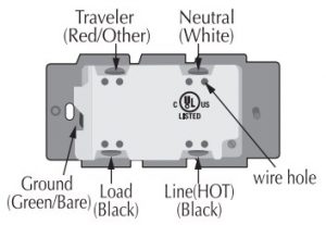
Step 2 ! WARNING ! RISK OF SHOCK !Make sure power if OFF before wiring !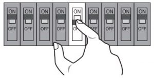
Step 3 :Remove the wall plate and the existing switch(if mounted) at your preferred installation location. You may label the wires connected to the screw terminals before disconnecting the switch. Please check that the wiring configuration below is present in the wall switch box, otherwise consult a qualified electrician.
- wires for 2-way circuit
- wires for 3-way circuit

- Line(Hot) – Black
- Neutral – White
- Ground — Green or Bare
- Traveler (3-way) Red or Other
- Load – Black
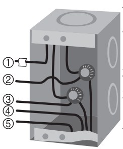
Wiring InformationUse copper wires only UL specification: the tightening torque for the screws is 14 Kgf-cm (12 Ibf-in) Strip insulation 5/8″ (16mm) Wire connection can be made either to
screw terminal
 14 AWG or larger rated at least 80 C
Hole
 14 AWG rated at least 80 C
2- way circuit
Making connection
3-way circuit
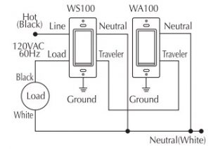
Making connection
Please refer to WA-100 user manual for wiring instructions of the auxiliary switch. The maximum length of Traveler wire may not exceed 200ft.
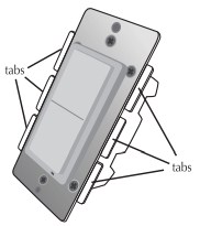
Gang BoxTo install the WS-100 in a single gang switch, no changes should be required. For dual or higher gang configuration where switches are next to each other, the tabs need b be removed Simply take a pair of piers, grab the tabs and wiggle and the tabs break off.
Step 4 :When proper wiring is completed, secure the module to the wall box. Restore power to the circuit to test if the connected load can be turned ON/OFF manually by the rocker on the module before remounting the wall plate. Also observe the status change of the LED indicator to ensure the module is in normal operating mode. If WA-100 Auxiliary Switch is used for a 3-way connection, please also test if it can control the load
Step 5 :Add(Include) the module into your network by a Z-Wave certified controller. Please refer to the controller’s instructions manual for details.
Manual Reset
Note: If Inclusion still fails after the 2nd attempt, you need to first reset the module before repeating the above steps. The manual reset method is as follows,
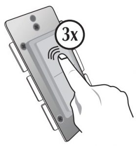
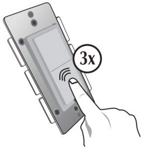
Quickly tap the top side (ON) of the rocker 3 times
Then, quickly tap the bottom side( OFF ) of the rocker 2 times
If you see the LED indicator blinks, it means that the module has been reset successfully and you may retry Step. 5 above to add the module into your network. Otherwise, please repeat the manual reset procedures.
Use the manual reset procedure only in the event that the network primary controller is lost.
BASIC OPERATION
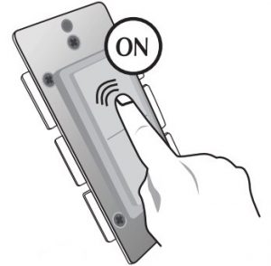
The connected appliance can be controlled manually with a push button

OR
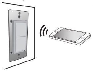
Wirelessly with a remote controller
A Z-Wave certified controller of either portable or static is capable of setting up Z-Wave Products units in your desired network. Once the module is added, you may assign it to a Group. It will change its reaction when the All command ON or OFF is received. Furthermore, it can be set in Association with another Z-Wave device to perform a specific function. Please refer to the instructions manual of your remote controller for details and procedures on how these settings can be done. Please note that the module will shut OFF after a power failure. The module will return to the last ON/OFF status after power restore.
About the rocker switch: There is only 1 rocker switch on this module for manual operation that allows you to
- Turn the connected appliance ON/OFF by tapping the switch. Tapping and releasing the upper part of the rocker turns the appliance ON. Tapping and releasing the lower part of the rocker turns the appliance OFF.
- Add(Include) or Delete(Exclude) the module to/from your Z-Wave network with your primary controller. Please refer to the instructions manual of your gateway or remote controller for details and procedures on how these actions can be done. Normally, the sequence is as follows: when the inclusion (or exclusion) process is prompted by your primary controller, single click and release the rocker switch => the controller should show that the action was successful => if the controller shows it was a fail, repeat the procedure.
Configurable ParametersThe following default settings can be changed if configurable parameters are supported by controller
The orientation of the ON/OFF on the rocker switch can be inverted by changing the following configuration with a controller (if supported) Parameter 4Length: 1 byteValid values: 0 or 1 (default 0)If value = 0, the connected light will turn ON by pressing the top side of the rocker switch and turn OFF by pressing the bottom side. If value = 1, the connected light will turn OFF by pressing the top side of the rocker switch and turn ON by pressing the bottom side.
About the LED indicator: By factory default, the LED indicator will be On when the connected appliance is On, and vice versa. This setting can be changed by the following methods,
- Configuration change with a controller(if supported) Parameter 3 Length: 1 byte Valid values: 0, 1 or 2 (default 0) When value = 0, the LED indicator will be ON when the connected appliance is ON,and the LED indicator will be OFF when the connected appliance is OFF If value = 1, the LED indicator will be On when the connected appliance is OFF, and the LED indicator will be Off when the connected appliance is ON If value = 2, the LED indicator will be always Off regardless of the load status
- Manually with the rocker switchQuickly short press the top(ON) of the rocker 2x and the bottom(OFF) of the rocker 2x,then the LED indicator will be always Off regardless of the load status. Repeating the proceduresabove restores the factory defauLt
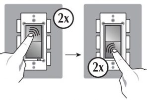 Quickly short press the top(ON) of the rocker 2x and the bottom(OFF) of the rocker 2x,then the LED indicator will be always Off regardless of the load status. Repeating the proceduresabove restores the factory defauLt
About the Z-Wave 500 Series module: You can use a Z-Wave certified portable or static controller to communicate with the module. Depending on the capability of your controller,the following simple to advanced operations can be performed.Please refer to the gateway or controller’s manual for details.
- Turn the appliance On/Off
- Add(include) or Delete(Exclude) the module to/from your network
- Assign the module to a specific Group and to set the reaction to All command
- Firmware update by PC static controller thru Over-The-Air
- To observe the Lifeline function which automatically notifies the associated modules and the network a manually reset unit is no longer in the network, thus, the corresponding association becomes invalid
Association :
- WS-100 supports association command class.
- WS-100 only supports group !11 for lifeline communication.
- You can associate up to 5 Z-Wave devices to group 1 .
- Lifeline association only supports the “manual reset” event.
- For instruction on how to “set lifeline associate ” , please refer to your wireless controller instruction.
Activation of Central Scene
Z-Wave Plus introduces a new process for scene activation – “Central Scene Control”. Press and release the button,it will send a certain command to the central controller via the lifeline association group 1. This allows the controller to read to key pressed,key released and key held down.
Scene Controller Parameters
Parameter 1 Length: 1 ByteValid Values : 0 to 99 (default=0)
| Valid Values | Configuration Option | |
| Top Button Scene Number | Bottom Button Scene Number | |
|
0 |
1 |
2 |
|
1 |
3 |
4 |
|
2 |
5 |
6 |
|
3 to 98 |
7,9,11 etc. |
8,10,12,etc. |
|
99 |
199 |
200 |
SPECIFICATION
| Model | WS-100 |
| Input power | 120VAC,60 Hz |
| Max output loading | 900W incandescent, 200W CFULED,1/2 horsepower motor and 1SA,1800W resistive load |
| Radio frequency | 908.4/916 MHz |
| Wireless range | up to 130 ft line of sight between the controller and the other available nodes |
| Normal operating temperature | 77°F (25°C)
For indoor use only |
Interoperability with Z-Wave devices
A Z-Wave network can integrate devices of various classes,and these devices can be made by different manufacturers. The Z-Wave Products unit introduced in this instructions manual has a Z-Wave certification which guarantees such an interoperability.
FCC ID: 2ABWCWS100
The Federal Communication Commission Radio Frequency Interference Statement includes the following paragraph:The equipment has been tested and found to comply with the limits for a Class B Digital Device,pursuant to part 15 of the FCC Rules. These limits are designed to provide reasonable protect on against harmful interference in a residential installation. This equipment uses,generates and can radiate radio frequency energy and,if not installed and used in accordance with the instruction, may cause harmful interference to radio communication. However,there is no guarantee that interference will not occur in a particular installation. If this equipment does cause harmful interference to radio or television reception,which can be determined by turning the equipment off and on,the user is encouraged to try to correct the interference by one or more of the following measures:
- Reorient or relocate the receiving antenna
- Increase the separation between the equipment and receiver
- Connect the equipment into an outlet on a circuit different from that to which the receiver is connected
- Consult the dealer or an experienced radio’TV technician for help
Operation is subject to the following two conditions:
- This device may not cause interference
- This device must accept any interference, including interference that may cause undesired operation of the device.
Important Note:To comply with the FCC RF exposure compliance requirements, no change to the antenna or the device is permitted. Any change to the antenna or the device could result in the device exceeding the RF exposure requirements and void user’s authority to operate the device.
Caution:Exposure to Radio Frequency Radiation.To comply with FCC/1C RF exposure compliance requirements,a separation distance of at least 20 cm must be maintained between the antenna of this device and all persons.This device must not be co-located or operating in conjunction with any other antenna or transmitter.
- Reorient or relocate the receiving antenna
- Increase the separation between the equipment and receiver
- Conned the equipment into an outlet on a circuit different from that to which the receiver is connected
- Consult the dealer or an experienced radio/TV technician for help
IC: 11786A-WS100
This device complies with Industry Canada license-exempt RSS standard(s).Operation is subject to the following two conditions:
- this device may not cause interference, and
- this device must accept any interference, including interference that may cause undesired operation of the device.
Z-Wave is a registered trademark of Sigma Design
WARRANTY
Z-Wave Products warrants to the original purchaser of this product that for the warranty period,this product will be free from material defects in materials and workmanship.The foregoing warranty is subject to the proper installation, operation and maintenance of the product in accordance with installation instructions and the operating manual supplied to customer. Warranty claims must be made by customer in writing within 30 days of the manifestation of a problem. Z-Wave Prcx:lucy sole obligation under the foregoing warranty is to repair, replace or correct any such defect that was present at the time of delivery, or to remove the product and to refund the purchase price to customer. The warranty does not extend to consequential or incidental damage to other products that may be used with this product. For inquiry and customer service,email to[email protected]
All brand names shown are trademarks of their respective owners
Warranty period: limited 1 year from date of purchase.
[xyz-ips snippet=”download-snippet”]