HIKVISION DS-PDPC12PF-EG2-WB/WE Wireless PIR-Camera Detector User Guide
DS-PDPC12PF-EG2-WB/WE Wireless PIR-Camera Detector
©2020 Hangzhou Hikvision Digital Technology Co., Ltd. All rights reserved. About this ManualThe Manual includes instructions for using and managing the Product. Pictures, charts, images and all other information hereinafter are for description and explanation only. The information contained in the Manual is subject to change, without notice, due to firmware updates or other reasons. Please find the latest version of this Manual at the Hikvision website (https://www.hikvision.com/).Please use this Manual with the guidance and assistance of professionals trained in supporting the Product.
HIKVISION
Disclaimer
TO THE MAXIMUM EXTENT PERMITTED BY APPLICABLE LAW, THIS MANUAL AND THE PRODUCT DESCRIBED, WITH ITS HARDWARE, SOFTWARE AND FIRMWARE, ARE PROVIDED “AS IS” AND “WITH ALL FAULTS AND ERRORS”. HIKVISION MAKES NO WARRANTIES, EXPRESS OR IMPLIED, INCLUDING WITHOUT LIMITATION, MERCHANTABILITY, SATISFACTORY QUALITY, OR FITNESS FOR A PARTICULAR PURPOSE. THE USE OF THE PRODUCT BY YOU IS AT YOUR OWN RISK. IN NO EVENT WILL HIKVISION BE LIABLE TO YOU FOR ANY SPECIAL, CONSEQUENTIAL, INCIDENTAL, OR INDIRECT DAMAGES, INCLUDING, AMONG OTHERS, DAMAGES FOR LOSS OF BUSINESS PROFITS, BUSINESS INTERRUPTION, OR LOSS OF DATA, CORRUPTION OF SYSTEMS, OR LOSS OF DOCUMENTATION, WHETHER BASED ON BREACH OF CONTRACT, TORT (INCLUDING NEGLIGENCE), PRODUCT LIABILITY, OR OTHERWISE, IN CONNECTION WITH THE USE OF THE PRODUCT, EVEN IF HIKVISION HAS BEEN ADVISED OF THE POSSIBILITY OF SUCH DAMAGES OR LOSS.
YOU ACKNOWLEDGE THAT THE NATURE OF INTERNET PROVIDES FOR INHERENT SECURITY RISKS, AND HIKVISION SHALL NOT TAKE ANY RESPONSIBILITIES FOR ABNORMAL OPERATION, PRIVACY LEAKAGE OR OTHER DAMAGES RESULTING FROM CYBER-ATTACK, HACKER ATTACK, VIRUS INSPECTION, OR OTHER INTERNET SECURITY RISKS; HOWEVER, HIKVISION WILL PROVIDE TIMELY TECHNICAL SUPPORT IF REQUIRED.
YOU AGREE TO USE THIS PRODUCT IN COMPLIANCE WITH ALL APPLICABLE LAWS, AND YOU ARE SOLELY RESPONSIBLE FOR ENSURING THAT YOUR USE CONFORMS TO THE APPLICABLE LAW. ESPECIALLY, YOU ARE RESPONSIBLE, FOR USING THIS PRODUCT IN A MANNER THAT DOES NOT INFRINGE ON THE RIGHTS OF THIRD PARTIES, INCLUDING WITHOUT LIMITATION, RIGHTS OF PUBLICITY, INTELLECTUAL PROPERTY RIGHTS, OR DATA PROTECTION AND OTHER PRIVACY RIGHTS. YOU SHALL NOT USE THIS PRODUCT FOR ANY PROHIBITED END-USES, INCLUDING THE DEVELOPMENT OR PRODUCTION OF WEAPONS OF MASS DESTRUCTION, THE DEVELOPMENT OR PRODUCTION OF CHEMICAL OR BIOLOGICAL WEAPONS, ANY ACTIVITIES IN THE CONTEXT RELATED TO ANY NUCLEAR EXPLOSIVE OR UNSAFE NUCLEAR FUEL-CYCLE, OR IN SUPPORT OF HUMAN RIGHTS ABUSES. IN THE EVENT OF ANY CONFLICTS BETWEEN THIS MANUAL AND THE APPLICABLE LAW, THE LATER PREVAILS.
 This product and – if applicable – the supplied accessories too are marked with “CE” and comply therefore with the applicable harmonized European standards listed under the EMCDirective 2014/30/EU, REDirective 2014/53/EU, the RoHS Directive 2011/65/EU.
 2012/19/EU (WEEE directive): Products marked with this symbol cannot be disposed of as unsorted municipal waste in the European Union. For proper recycling, return this product to your local supplierupon the purchase of equivalent new equipment, or dispose of it at designated collection points. For more information see: www.recyclethis.info
 replacement of a battery with an incorrect type that can defeat a safeguard (for example, in the case of some lithium battery types); — disposal of a battery into fire or a hot oven, or mechanically crushing or cutting of a battery, that can result in an explosion; — leaving a battery in an extremely high temperature surrounding environment that can result in an explosion or the leakage of flammable liquid or gas; and — a battery subjected to extremely low air pressure that may result in an explosion or the leakage of flammable liquid or gas
 2006/66/EC (battery directive): This product contains a battery that cannot be disposed of as unsorted municipal waste in the European Union. See the product documentation for specific battery information. The battery is marked with this symbol, which may include lettering to indicate cadmium (Cd), lead (Pb), or mercury (Hg). For proper recycling, return the battery to your supplier or to a designated collection point. For more information see:www.recy-clethis.info
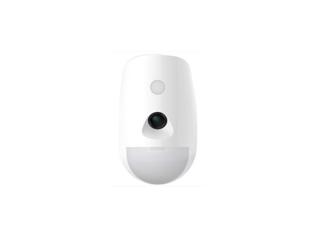
1 Appearance

2 Enrollment
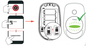
Note: The enrollment progress will be completed in 3 to 10 seconds normally.
- Log in to the APP Store, download and install the
- Power on the security control
- Log in the APP and tap the icon “+” . Scan the QR code or input the control panel serial to add the control panel.
1 Enroll the Peripheral Locally
- In the APP, tap the “Enrollment Mode” button on the control panel page to make the control panel enter the enrollment
- Loosen the screw and remove rear
- Power on the peripheral, and it will be automatically enrolled to the control panel

Note: make the device power off, hold the tamper switch and then power on for re-enrollment synchronously. The distance between the detector and AXPRO should be less than 50 cm.
2 Enroll the Peripheral with QR and serial No.
- In the APP, tap the icon “+”and scan the QR code or serial on the peripheral.
- Loosen the screw and remove rear
- Power on the peripheral, and it will be automatically enrolled to the control

3 Installation
-
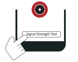
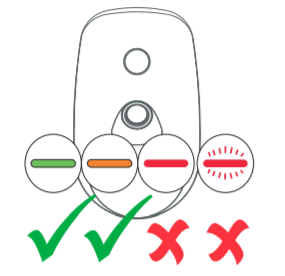
- Check Signal Strength Enter the signal checking mode by operating on the control panel. Trigger the detector. Solid Green for 3 s – Strong SignalSolid Orange for 3 s – Medium Signal Solid Red for 3 s – Weak SignalRed light flashes for 3S – Failure


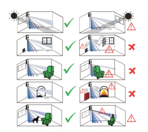
- Check the installation environment

- Install the DetectorNote: The additional force shall be equal to three times the weight of the equipment but not less than 50N. The equipment and its associated mounting means shall remain secure during the installation. After the installation, the equipment, including any associated mounting plate, shall not be damaged.Make sure there is no obstacle sheltering the LENs and IR light.with Screwsa. Knock out the screw holes on the rear panel.
 B. Secure the rear panel on the wall with four
 with the Sponge TapePaste the device on the wall with sponge tape.
 You can paste the detector on the wall or in the corner.Note: Installing with sponge tape is non EN compliant.
- Check Signal Strength Enter the signal checking mode by operating on the control panel. Trigger the detector. Solid Green for 3 s – Strong SignalSolid Orange for 3 s – Medium Signal Solid Red for 3 s – Weak SignalRed light flashes for 3S – Failure
Bracket InstallationCeiling Bracket Fitting (Non EN compliant)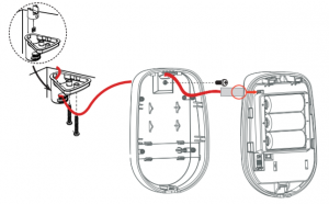
Wall Bracket Fitting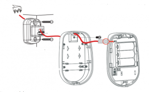
4. Test
Detector zones and planesThe zones and plans of the PIRCAM are shown below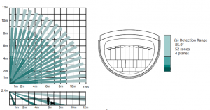
While the detector is disarmed, the detector will enter the walk test mode (within 3 minutes after being enrolled). Trigger the detector within the detection range.If the LED indicator turns blue, the installation position is properly. If the LED indicator is still off, adjust the position of the detector.
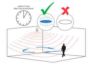
Note: while the detector is disarmed, power off and power on will make the detector enter the walk test mode.
5 Formatting
Hold the tamper switch for 8 s and power the device on at the same time. The red LED flashes 3 times when the formatting operation is completed
6 Set up with App
Link the detector to the zone.On the device list page, tap the AX PRO and then log in to the device (if required) to enter the Area page. Tap Device, and tap the zone.You can view the device status including temperature, battery status, signal strength, etc. Tap the button in the upper right corner to enter the Settings page
Function DescriptionZone Type Select the zone type of the detectorStay Arm Bypass Slide to green to bypass the zone from stay arming.Forbid Bypass on Arming Slide to green to forbid the zone with fault to be bypassed automatically when arming.Chime Slide to green to enable the chime.Silent Alarm Slide to green to make the zone keep silent while alarm is triggered.Sounder Delay Time Set the delay time. The sounder will be triggered immediately or after the set timeCross Zone If the alarm triggered in both of the linked zones within the set time, two alarm messages will be reported.Sensitivity Set the sensitivity of the detector. Higher sensitivity makes the intruder easier to be detected.Image Resolution Set the resolution of the image.Image in Series Set the captured image number in series.Swinger limit activations Set the limit times of swinger activition .Trigger Interval, sec Set the interval of trigger, and the alarm message will not be repeated within the time.LED Turn On/Off the LED.Signal Strength Test Enter the test mode, and view the LEDPolling Rate Set the interval of heartbeat.Detection Zone Test Enter the test mode, and start walk test. indication.Bypass Slide to green to bypass the zone.Find Me Tap Find Me to make peripherals find the zone.
5 Operation Caution and Device Maintenance
- All the electronic operation should be strictly compliance with the electrical safety regulations, fire prevention regulations and other related regulations in your local
- Do not drop the device or subject it to physical shock, and do not expose it to high electromagnetism Avoid the equipment installation on vibrations surface or places subject to shock (ignorance can cause equipment damage).
- Please make sure that the power has been disconnected before you wire, install or dismantle the
- If smoke, odors or noise rise from the device, turn off the power at once and unplug the power cable, and then please contact the service center.
- Do not drop the device or subject it to physical shock, and do not expose it to high electromagnetism Avoid the equipment installation on vibrations surface or places subject to shock (ignorance can cause equipment damage).
- Do not place the device in extremely hot (refer to the specification of the device for the detailed operation temperature), cold, dusty or damp locations, and do not expose it to high electromagnetic
- The device for indoor use shall be kept from rain andExposing the equipment to direct sun light, low ventilation or heat source such as heater or radiator is forbidden (ignorance can cause fire danger).
- Do not aim the device at the sun or extra bright A blooming or smear may occur otherwise (which is not a malfunction however), and affecting the endurance of sensor at the same time.
- Improper use or replacement of the battery may result in hazard of Replace with the same or equivalent type only. Dispose of used batteries according to the instructions provided by the battery manufacturer.
- Do not expose the device to the corrosive Otherwise the equipment damage may occur.
- Do not expose the device to the explosive
8 Specification
| Model | DS-PDPC12PF-EG2-WB/WE | |
|
Detection Performance |
Detection Method | Passive Infrared,Video Verification |
| Sensor Model | SFG321-711 | |
| Detection Range | 12m | |
| Detection Angle | 85.9° | |
| Detection Zones | 52 | |
| Detectable Speed | 0.3 to 2m/s | |
| Sensitivity | Auto,High,Pet | |
| Pet Immunity | 30Kg | |
| White Light Filter | 6500lux | |
| Digital Temperature Compensation | Support | |
| Creep Zone Protection | Support | |
|
Feature |
Digital Processing | Support |
| Sealed Optics | Support | |
| Tamper Protection | Front,Rear | |
| Environment Temperature Indicator | Support | |
| Signal Strength Indicator | Support | |
|
Video |
Image Sensor | ASX340 |
| Field Angle | 88°(H), 68°(V) | |
| Image Type | JPEG | |
| Resolusion | 640*480,320*240,160*120 | |
| Frame Rate | 2 | |
| Fill Light | White Light | |
| Fill Range | 12m | |
| Day/Night Switch | Color | |
| Interface | Power Switch | Power Up Enrolling |
| LED Indicator | Blue(Alarm) | |
|
Transmission |
Transmission Technology | CAM-X Wireless |
| Transmission Method | Two-Way RF Wireless | |
| Transmission Frequency | 433MHz/868MHz | |
| Transmission Security | AES-128 Encryption | |
| Transmission Range(Free Space) | 800m | |
| Enrolling Method | Power up,Remote ID,QR Code | |
|
Electrical Characteristics |
Power Supply | Battery Powered |
| Battery Type | CR123A × 3 | |
| Typical Voltage | 3V | |
| Low Voltage Value | 2.45 V | |
| Consumption | Max. current: 1.5A
Quiescent current: 10uA |
|
| PS Type | Type C | |
| Standard Battery Life | 6 Years | |
|
General |
Operation Temperature | -10 °C to 55 °C (14 °F to 131 °F) |
| Storage Temperature | -20 °C to 60 °C (-4 °F to 140 °F) | |
| Operation Humidity | 10% to 90% | |
| Dimension(WxHxD) | 72.2mm × 120.5mm × 56.7mm | |
| Weight | 220g | |
| Mounting Height | 1.8 to 2.4m | |
| Mounting Method | Wall | |
| Application Scenario | Indoor | |
| Bracket | Optional Wall & Ceiling Accessory |
9 Reference Table
| 1st Photo transmission time | |
| – 160 x 120 | 5s (5KB per image) |
| – 320 x 240 | 6s (10KB per image) |
| – 640 x 480 | 12s (60KB per image) |
| Internal memory buffer | |
| – 160 x 120 | 160 images (5KB per image) |
| – 320 x 240 | 80 images (10KB per image) |
| – 640 x 480 | 25 images (30KB per image) |
Read More About This Manual & Download PDF:
References
[xyz-ips snippet=”download-snippet”]


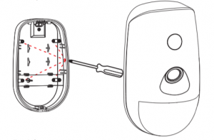 B. Secure the rear panel on the wall with four
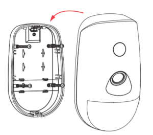 with the Sponge TapePaste the device on the wall with sponge tape.
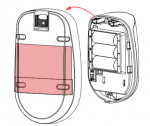 You can paste the detector on the wall or in the corner.Note: Installing with sponge tape is non EN compliant.