
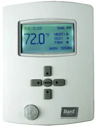
Bard CompleteStat Controller
NOTEScreenshots shown in this manual reflect default settings (when applicable).
INSTALLATION
IMPORTANT: For optimum temperature sensor performance, the Bard CompleteStat must be mounted on an interior wall and away from any heat sources, sunlight, windows, air vents, air circulation obstructions and/or any other cause of erratic or false temperature sensing. Thermostat covers are not recommended as they interfere with motion and temperature sensing.
Mounting Controller
- It is recommended that18 AWG solid-conductor control wire is used for installation. See the low voltage wiring diagrams beginning on page 15 for exact number of conductors.NOTE: Shielded wire must be used in applications where transient signals may accumulate and affect digital signal from control to unit.
- Turn the hex screws in the bottom and top of the controller clockwise (inward) until they clear the cover. Remove base plate from controller.
- Route control wiring through base plate.
- With the embossed “UP” arrows of the base plate pointing in the appropriate direction, fasten the base plate to the desired wall location. A vertical/horizontal 2×4 wall handybox can be used for the CO2-sensing CompleteStat and a vertical-only 2×4 wall handy box can be used for non-CO2-sensing CompleteStat.
- Make appropriate control wire connections to terminal blocks. See low voltage wiring diagrams beginning on page 15.
- Replace controller over base plate, being careful not to pinch/dislodge connections.
- Turn hex screws in bottom/top of controller counter-clockwise (outward) to secure cover.
|
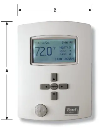
Models |
Dimensions in Inches (mm) | ||
| Height (A) | Width (B) | Depth | |
| CS9B(E)-THOA | 5.551
(141) |
4.192 (106) | 1.125 (29) |
| CS9B(E)-THOCA | 5.192 (132) | 1.437 (36.5) |
BASIC OPERATION
BASIC SETUP
These instructions are intended to provide the basic settings to get the equipment started.
Complete Stat Buttons and Home, Override and Configuration ScreensNavigate the menus and change settings by pressing a combination of the four arrow buttons and the ENTER button.
- ENTER button to select and/or exit value editing
- UP or DOWN button to move among entries
- RIGHT or LEFT button to move among value fields
- LEFT button to return to the home screen
NOTE:
- Although cooling/heating setpoints can be accessed by simply pressing the UP or DOWN buttons during normal operation, any changes made in this fashion will not be permanent but last only for a specific length of time as an “override” feature. See Setpoints on page 9 for further information.
- The screen will revert back to the home screen if inactive for “X” number of seconds (factory default is 120 seconds). See page 14 in the latest version of CompleteStat Controller Advanced Programming & Features 2100-685 for information on adjusting the inactivity setting.
- If the screen includes up and down arrows in the upper corners (as shown in Figure 7 on page 7), additional choices can be found by continuing to press the UP or DOWN buttons.
QUICK START PROGRAMMING
System SelectionTo select A/C or HP, stages of heating and cooling, and with/without economizer:
- Press RIGHT button to access Main Menu screen.
- Press DOWN button to scroll to TECHNICIAN. Press ENTER button.
- Controller will ask for password. Press UP and RIGHT buttons to enter ‘BARD’. Press ENTER button.
- Press ENTER button again to enter the APPLICATION menu (see Figure 3).

- Press ENTER button again to choose DEGREES.NOTE: The UNIT_TYPE category must be set to “NOT CONFIGURED” before the controller will allow the scale to be changed (see step 7 on page 6).
- Press UP or DOWN button to choose °F (Fahrenheit) or °C (Celsius). Press ENTER to save selection of scale.NOTE: The change from F to C will not take effect on the home screen until the 24VAC power is cycled off and back on.
- Press DOWN button to scroll to UNIT_TYPE. Press ENTER button.
- Press UP or DOWN button to choose from the available system types (A/C, HP or Not Configured).
- Press ENTER button to select/save appropriate choice.
- Press DOWN button to scroll to OPT. Press ENTER button.
- Press UP or DOWN button to choose from the following available system stages:
- A/C – 1H/1C
- A/C – 2H/2C
- A/C – 1H/2C
- A/C – 2H/1CNOTE: These are stages of compressor operation.
- Press ENTER button to select/save appropriate model stage.
- Press DOWN button to scroll to ADDITIONAL SETUP. Press ENTER button.
Air Conditioner Applications (see Figure 4)NOTE: The following is for A/C applications. Heat pump application information can be found in the following section.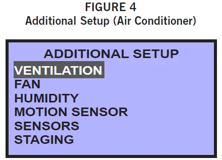
Ventilation, Fan and Humidity Setup
- Press ENTER button to enter VENTILATION menu.
- Press ENTER button to highlight ECON options. Press UP or DOWN button to choose from the available economizer options:• NONE = No economizer, or standard vent package (ERV/CRV/MFAD)• EN/DIS = Economizer in system
- Press ENTER button to select/save appropriate economizer option.
- Press LEFT button to go back to ADDITIONAL SETUP.
- The indoor blower can be set for ON or AUTO in either occupied or unoccupied conditions. To access or change blower settings, press DOWN button to scroll to FAN. Press ENTER button to enter FAN SETUP (see Figure 5).
- Press DOWN button to scroll through selections; adjust as necessary.• Speeds: Constant speed (nonadjustable)• Off Delay: “0” = System fan will run for specified time after call ends; 0-600 seconds in 30-second increments.• Unocc: “ON” = System fan will run continuously during all operational modes; “AUTO” = System fan will operate during call for cooling or heating, but will cycle off when no compressor or no heating is needed (factory default).• Occ: “ON” = System fan will run continuously during all operational modes; “AUTO” = System fan will operate during call for cooling or heating, but will cycle off when no compressor or no heating is needed (factory default).
- Press ENTER button to save changes to FAN mode selections.
- Press LEFT button to go back to ADDITIONAL SETUP.
- Press DOWN button to scroll to HUMIDITY. Press ENTER button to enter HUMIDITY SETUP.
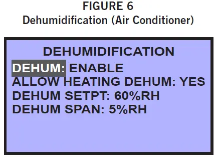
- Press DOWN button to scroll to DEHUMIDIFICATION. Press ENTER button (see Figure 6).
- Press ENTER button again to highlight current dehum choice (default is ENABLE).
- Press UP or DOWN button to toggle ENABLE/DISABLE. Press ENTER button to select/save choice.
- Press DOWN button to scroll through additional DEHUMIDIFICATION screen choices:• ALLOW HTG DEHUM = Allows dehumidification in heating: YES/NO (default is YES).• DEHUM SETPT = Relative Humidity (RH) setpoint: 45% RH to 80% RH, 1% increments (default is 60%RH).• DEHUM SPAN = Amount of RH% removal allowed past setpoint: 5% to 10%, 1%increments (default is 5%RH).
- Press ENTER button to save changes.
- Press LEFT button to return to the home screen. Proceed to System Enable on page 9 to continue the setup process.Heat Pump Applications (see Figure 7)NOTE: The following is for heat pump applications. A/C application information can be found in the previous section.

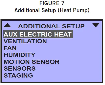
Auxiliary Electric Heat Setup
If the heat pump selection is chosen, electric heat must be configured. These steps do not apply to air conditioners or other types of conventional heating. To configure the auxiliary heat from the home screen:
- Press RIGHT button to access Main Menu screen.
- Press DOWN button to scroll to TECHNICIAN. Press ENTER button.
- Controller will ask for password. Press UP and RIGHT buttons to enter ‘BARD’. Press ENTER button.
- In the TECHNICIAN menu screen, press ENTER button to enter the APPLICATION menu.
- Press DOWN button to scroll to ADDITIONAL SETUP. Press ENTER button.
- Press ENTER button again to choose AUX ELECTRIC HEAT.
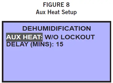
- Press ENTER button again to highlight current AUX HEAT choices (see Figure 8).
- Press UP or DOWN button to scroll through AUX HEAT screen choices:• W/O LOCKOUT = Auxiliary heat will activate regardless of compressor operation or outdoor air temperature (factory default). If W/O LOCKOUT is chosen, proceed to set delay-on time (Step 9).• COMP LOCKOUT = Compressor locks out below the selected outdoor air temperature. Requires optional Bard 8403-061 Outdoor Air Temperature Sensor.• NONE = No auxiliary strip heat; controller will not energize W2. If NONE is chosen, press LEFT button to return to the home screen.
- Press DOWN button to highlight DELAY (MINS).
- Press ENTER button to highlight default DELAY minutes.
- Press UP or DOWN button to select amount of minutes desired to delay the electric heat before activation: 10-120 minutes, in 10 minute increments (factory default 15 minutes). Press ENTER button to save choice.
- Press LEFT button to return to ADDITIONAL SETUP.
If COMP LOCKOUT was chosen during the heat strip configuration process, an optional outdoor air temperature sensor will have to be installed/configured to specifically set the temperature at which the compressor will no longer be allowed to operate. Refer to the latest version of CompleteStat Controller Advanced Programming & Features 2100-685 to configure the outdoor air temperature sensor.To install Bard 8403-061 Outdoor Air Temperature Sensor, attach the leads to terminals “OAT” and “GND”. To set the compressor outdoor air temperature limits from the home screen:
1. Press RIGHT button to access Main Menu screen.2. Press DOWN button to scroll to TECHNICIAN. Press ENTER button.3. In the TECHNICIAN menu screen, press UP or DOWN button to scroll to LIMITS. Press ENTER button.4. Press DOWN button to scroll to COMP OAT CLG LOW. Press ENTER button.5. Press UP or DOWN button to select outdoor air temperature for compressor lockout (factory default 0ºF). Press ENTER to save choice.6. Press LEFT button to return to TECHNICIAN menu.
Ventilation, Fan and Humidity Setup
- In the TECHNICIAN menu screen, press ENTER button to enter the APPLICATION menu.
- Press DOWN button to scroll to ADDITIONAL SETUP. Press ENTER button.
- Press DOWN button to scroll to VENTILATION. Press ENTER button.
- Press UP or DOWN button to choose from the available economizer options:• NONE = No economizer, or standard vent package (ERV/CRV/MFAD). This is the factory default.• EN/DIS = Economizer in system
- Press ENTER button to select/save appropriate economizer option.
- Press LEFT button to go back to ADDITIONAL SETUP.
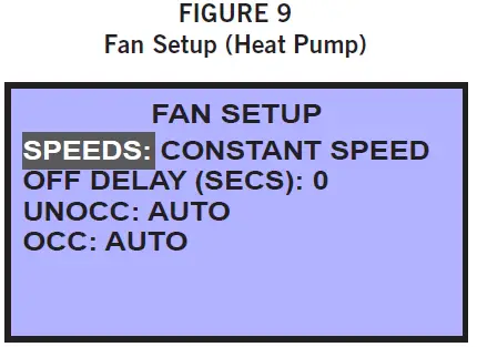
- The indoor blower can be set for ON or AUTO in either occupied or unoccupied conditions. To access or change blower settings, press DOWN button to scroll to FAN. Press ENTER button to enter FAN SETUP (see Figure 9).
- Press DOWN button to scroll through selections; adjust as necessary.• Speeds: Constant speed (nonadjustable)• Off Delay: “0” = System fan will run for specified time after call ends; 0-600 seconds in 30-second increments.• Unocc: “ON” = System fan will run continuously during all operational modes; “AUTO” = System fan will operate during call for cooling or heating, but will cycle off when no compressor or no heating is needed (factory default).• Occ: “ON” = System fan will run continuously during all operational modes; “AUTO” = System fan will operate during call for cooling or heating, but will cycle off when no compressor or no heating is needed (factory default).
- Press ENTER button to save changes to FAN SETUP selections.
- Press LEFT button to go back to ADDITIONAL SETUP.
- Press DOWN button to scroll to HUMIDITY. Press ENTER button to enter HUMIDITY SETUP.
- Press ENTER button again to choose DEHUMIDIFICATION (see Figure 10).
- Press ENTER button again to highlight current dehum choice (default is ENABLE).
- Press UP or DOWN button to toggle ENABLE/DISABLE. Press ENTER button to select/save choice.
- Press DOWN button to scroll through additional DEHUMIDIFICATION screen choices:• ALLOW HTG DEHUM = Allows dehumidification in heating as well as cooling: YES/NO (default is YES).• DEHUM SETPT = Relative Humidity (RH) setpoint: 45% RH to 80% RH, 1% increments (default is 60%RH).• DEHUM SPAN = Amount of RH% removal allowed past setpoint: 5% to 10%, 1%increments (default is 5%RH).
- Press ENTER button to save changes.

Reversing Valve Setup
- Press LEFT button two (2) times to return to ADDITIONAL SETUP.
- Press UP or DOWN buttons to scroll to VALVE (see Figure 11). NOTE: VALVE does not show up on first screen. Continuing to press the UP or DOWN button will display VALVE.
- Press ENTER button to highlight choice of ACTIVE HTG or ACTIVE CLG. Press UP or DOWN button to toggle between the choices. Press ENTER button to save choice.
- Press LEFT button to return to the home screen.

System Enable
To enable heating or cooling from the home screen:
- Press RIGHT button to access the Main Menu screen.
- Press ENTER button to enter the SYSTEM menu (see Figure 12).
- Press ENTER button to choose from available SYSTEM ENABLE options (use UP or DOWN buttons to scroll through choices):• AUTO (factory default) = System is in “Auto-Changeover” mode. HVAC system will cycle heating and cooling automatically to stay within preset heating and cooling setpoints.• EMER HT = HP mode only.• OFF = HVAC system is inactive.• COOLING = System is in “Cooling-Only” mode. HVAC system will cycle cooling in reference to cooling setpoint only. Unit will not activate heating sequence.• HEATING = System is in “Heating-Only” mode. HVAC system will cycle heating in reference to heating setpoint only. Unit will not activate cooling sequence.
- Press ENTER button to save choice.
- Press LEFT button to return to the home screen.
Setpoints
To access setpoints from the home screen:
- Press RIGHT button to access the Main Menu screen.
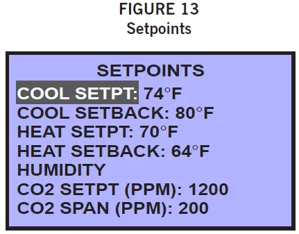
- Press DOWN button to scroll to SETPOINTS. Press ENTER button (see Figure 13). Factory default values are shown in the figure.
- Press ENTER button to select COOL SETPT.
- Press UP or DOWN buttons to enter appropriate cooling setpoint. Press ENTER button to save new cooling setpoint.
- Press DOWN button to scroll to HEAT SETPT. Press ENTER button.
- Press UP or DOWN buttons to enter appropriate heating setpoint. Press ENTER button to save new heating setpoint.
- Follow the steps provided above to adjust cooling and heating setback temperatures, dehum setpoint and span, and CO2 setpoint and span of control in parts per million (if available).
- Press LEFT button to return to the home screen.
NOTE: The controller will not allow heating/cooling setpoints to contradict one another, or to be within a degree of conflicting operation.NOTE: Any system startup with indoor ambient temperatures lower than 56°F or above 86°F, or humidity higher than 65%, will experience an internal Low Temperature or High Temperature alarm. This will not affect normal operation and can be cleared easily.
 report this ad
Bard CompleteStat should be operational at this point. For further controller enhancement or operation detail, please consult the latest edition of CompleteStat Advanced Programming & Features 2100-685.
References
[xyz-ips snippet=”download-snippet”]