![]()
Bard Electronic Expansion Valve (EEV) and Service Tool Instruction Manual

Models: Q24H4D Q30H4D Q36H4D Q43H4D Q48H4D
![]() Bard Manufacturing Company, Inc.Bryan, Ohio 43506www.bardhvac.com
Bard Manufacturing Company, Inc.Bryan, Ohio 43506www.bardhvac.com
Manual: 7960-922Supersedes: NEWDate: 8-13-21
Q**H4D dehumidification models provide a unique dehumidification circuit for periods of low outdoor ambient temperature and high indoor humidity conditions.
Refer to Spec Sheet S3607 for the standard features of the base units and this manual for electrical data.
Dehumidification Circuit
The dehumidification circuit incorporates an independent heat exchanger coil in the supply air stream. This coil uses discharge gas to reheat the supply air after it passes over the cooling coil without requiring the electric resistance heater to be used for reheat purposes. This results in very high mechanical dehumidification capability from the air conditioner on demand without using electric resistance reheat.
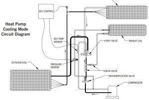
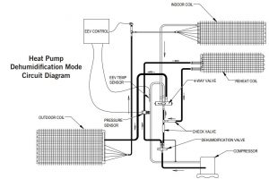
The dehumidification refrigerant reheat circuit is controlled by a dehumidification valve directing the refrigerant gas to the normal condenser during periods when standard air conditioning is required. During periods of time of low ambient temperature (approximately 65° to 75° outdoor) and high indoor humidity, a humidistat senses the need for mechanical dehumidification. It then energizes both the compressor circuit and dehumidification valve, thus directing the hot refrigerant discharge gas into a separate desuperheating condenser circuit, which reheats the conditioned air before it is delivered to the room. The refrigerant gas is then routed from the desuperheating condenser to the system condenser for further heat transfer. When the humidistat is satisfied, the system automatically switches back to normal operation and either continues to operate or turns off based on the signal from the wall thermostat. The result is separate humidity control at minimum operating cost.
Dehumidification Sequence of Operation
Dehumidification is controlled through the thermostat (if capable) or through a separate humidistat. On a call for dehumidification mode of operation, the compressor and dehumidification valve of the unit are energized through circuit R – D to provide dehumidification. Dehumidification will continue until the humidistat is satisfied.
A cooling call takes precedence over a dehumidification call for as long as the cooling call is present.
A heating call takes precedence over a dehumidification call unless an occupied signal is received. When occupied, a dehumidification call takes precedence over first stage heating. A second stage heating call takes precedence over a dehumidification call even when occupied.
Refer to the chart on page 11 for a full list of outputs that can be expected for different input combinations.
Balanced ClimateTM Mode
Enable Balanced Climate mode for cooling operation ONLY and utilize a 2-stage thermostat to enhance the comfort. To activate this mode, the jumpers between Y1 and Y2 on both low voltage terminal strips (blower section and control panel) need to be removed. Refer to unit wiring diagram for clarity.
This mode will allow the indoor blower to run at a reduced airflow on the first stage of cooling. A 2-stage thermostat connected to Y2 will then allow the airflow to return to normal rated speed if the call for cooling is not satisfied within the allotted time frame specified by the thermostat.
Electronic Expansion Valve
OperationThis model employs an electronic expansion valve (EEV) which meters the refrigerant to the evaporator. In the heat pump application, the EEV is used bi-directionally to meter the refrigerant in both heating and cooling modes. The EEV is made of a stepper motor that is controlled with a step output from the controller. The valve is capable of 480 steps which drives a needle valve that in turn regulates the flow of refrigerant. The EEV allows for tighter control and better capacity management in varying operating conditions than a standard TXV. The EEV system consists of the electronic valve and stator, control board, relay, suction temperature sensor and suction pressure transducer. The pressure transducer and temperature sensor monitor the suction line to provide real time data to the control board so that a real time superheat can be calculated. This then determines the EEV position. The controller is set to maintain around 19° superheat. The relay is used to activate the EEV system’s controller anytime that the compressor is energized.
EEV Instructions for Vacuuming, Reclaiming and Charging Unit
 WARNINGExposure to high pressure refrigerant hazard.This unit is equipped with an electronic expansion valve (EEV). In order to fully recover refrigerant or evacuate system during repairs, either use service tool P/N 2151- 021 to manually open the EEV or be sure to recover and evacuate from all service ports: suction, liquid and discharge.
Failure to do so could result in eye injuries and/or refrigerant burns.
DO NOT connect to the high pressure service port on the front of the unit with the RED circular label. This connection point is under very high pressure and could cause injury and/or refrigerant burns.
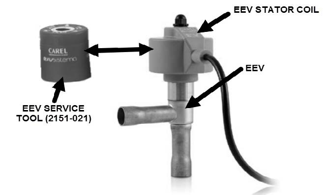
The electronic expansion valve moves to a closed position when there is no call to control. In order to pull a complete vacuum, fully reclaim the system or charge the unit, connections to the suction and liquid line service ports need to be utilized or the valve needs to be manually opened first. The valve can be opened manually using the magnetic EEV service tool (Bard P/N 2151-021) shown in Figure 1. To do this, remove the EEV stator coil (red color with retaining nut on top), slide the magnetic tool over the shaft where the stator was removed and turn in a clockwise direction to open the valve to the full open position (directional arrows are provided on the tool).
FIGURE 1Electronic Expansion Valve (EEV) and Service Tool
Reapply the EEV stator coil and retaining nut once complete. Upon powering the unit back up, the control board will automatically drive the EEV back to the fully shut position. Once the compressor starts, the control board will again modulate the EEV position to control the system superheat.
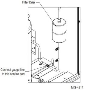
The high side connection should be made at the service port located on the liquid line assembly near the unit base on the right side of the unit (see Figure 2).
FIGURE 2High Side Connection
Troubleshooting the Electronic Expansion Valve
The control board has two status LEDs.
- The green LED should be lit anytime that the board has power and the control is functioning.
- The red LED is to show that an alarm is present.
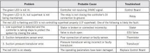
See Table 1 for a guide to know where to start troubleshooting the EEV. Refer to the appropriate unit replacement parts manual for any parts that are needed.
Control BoardCheck that the controller is getting 24VAC signal (GO 24VAC Hot and G 24VAC common). Reference unit wiring diagram for proper connections. If 24V is present but the green LED is not lit, replace the controller. If the green LED is now lit but the superheat is still not being maintained, troubleshoot the relay to check that the DI is connected to G; refer to Relay in EEV Control Box.
Electronic Expansion ValveCheck to see if valve can be moved by manually moving the stepper motor using the EEV service tool shown in Figure 1 (Bard Part # 2151-021). If valve still does not control, check the transducer and thermistor sensors as described on page 4. If sensors are good, replace the valve.
Relay in EEV Control BoxContacts NO to DI and COM to G must be closed for EEV control to start controlling superheat. Check that the relay is getting 24VAC. Reference unit wiring diagram for proper connections. If 24V is present, measure the resistance between COM and NO; it should be 0 ohms when the relay is getting 24V. If the resistance is out of range, replace the relay.
Stator CoilDisconnect the stator from the valve and the control and measure the resistance of the windings using an electrical tester. The resistance of both windings should be around 40 ohms +/– 10%. The four wire sets that will have resistance between them are: White and red, green and red, yellow and purple, blue and purple. If the resistance falls outside these values, replace the stator.
Transducer Sensor
- Check continuity of all three wires from transducer plug to controller plug. Replace wires if poor connection in any wire.
- Check to ensure wires are correctly connected as follows:Blue wire = pin 1 of controller plug to pin C on transducer plugRed wire = pin 2 of controller plug to pin B on transducer plugBlack wire = pin 3 of controller plug to pin A on transducer plug
- Check that there is 5VDC Nominal between the red and black wires going to the transducer.
- Check the signal voltage between the blue and black wires (0.5-4.5VDC Actual). The following formula and Figure 3 can be used to determine if the transducer’s voltage to pressure ratio is within range. Replace transducer if out of range.
Formula for Tech:(Measured Pressure x .016) + .5 = Expected Transducer Signal Voltage (see Figure 3).
FIGURE 3Voltage to Pressure: Suction Pressure Transducer
![]()
TABLE 1Electronic Expansion Valve Troubleshooting
Thermistor Sensor
- Make a visual check for broken wire insulation, broken wires or cracked epoxy material.
- Disconnect 10k ohm NTC thermistor from the EEV control box.
- Use an ohmmeter to measure the resistance between the two connectors. Also use ohmmeter to check for short or open.
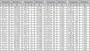
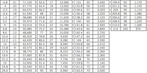
- Compare the resistance reading to Table 2. Use sensor ambient temperature. (Tolerance of part is ±10 %.)
- If sensor is out of tolerance, shorted, open or reads very low ohms, it should be replaced.
TABLE 210K Ohm NTC Sensor: Temperature/Resistance
Heat Pump Cooling Mode Circuit Diagram
Heat Pump Dehumidification Mode Circuit Diagram
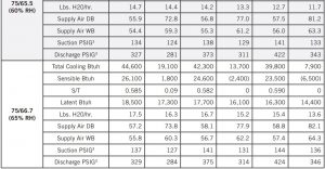
Cooling and Dehumidification Application Data1
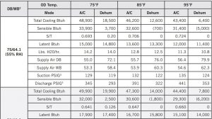
Q24H4D Cooling and Dehumidification Application Data1

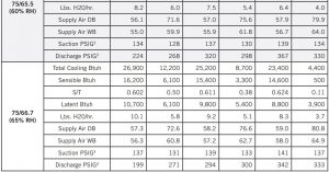
1 Values listed are with ventilation package disabled2 Return air temperature °F @ Default airflow (825 CFM) for AC tests and Balanced Climate airflow (600 CFM) for dehumidification tests3 Suction pressure +/- 4 psi, Discharge pressure +/- 10 psi
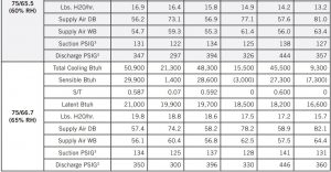
Q30H4D Cooling and Dehumidification Application Data1

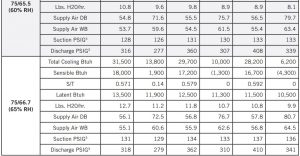
1 Values listed are with ventilation package disabled2 Return air temperature °F @ Default airflow (900 CFM) for AC tests and Balanced Climate airflow (650 CFM) for dehumidification tests3 Suction pressure +/- 4 psi, Discharge pressure +/- 10 psi
Q36H4D Cooling and Dehumidification Application Data1
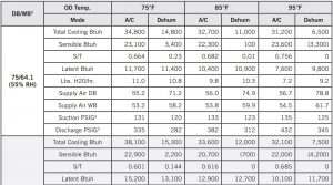
1 Values listed are with ventilation package disabled2 Return air temperature °F @ Default airflow (1125 CFM) for AC tests and Balanced Climate airflow (825 CFM) for dehumidification tests3 Suction pressure +/- 4 psi, Discharge pressure +/- 10 psi
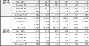
Q43H4D Cooling and Dehumidification Application Data1
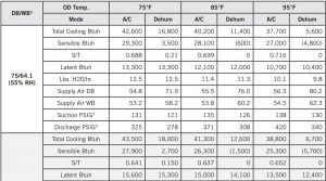
Q48H4D Cooling and Dehumidification Application Data1
1 Values listed are with ventilation package disabled2 Return air temperature °F @ Default airflow (1500 CFM) for AC tests and Balanced Climate airflow (1050 CFM) for dehumidification tests3 Suction pressure +/- 4 psi, Discharge pressure +/- 10 psi
TABLE 3Dehumidification Relay Logic Board
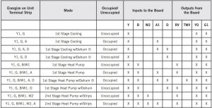
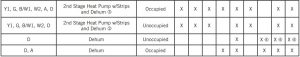
- Cooling takes precedence over dehumidification. A cooling call cancels dehumidification.
- When occupied (for either jumper position), dehumidification takes precedence over first stage heating.
- A second stage heating call always takes precedence over dehumidification.
- The relay logic board has a jumper (J1) on it to choose between “any-time dehumidification” and “occupied dehumidification”. The factory default is P1-P2. With the jumper in the P1-P2 position, dehumidification is available any time there is a “D” input to the relay logic board. With the jumper in the P2-P3 position, dehumidification is available when there is an occupancy signal to the “A1” terminal, “D” would also need to be energized to dehumidify.
Refer to sequence of operation. In most cases cooling and heating modes take priority over dehumidification.
TABLE 4Electrical Specifications – Q**H4D Series
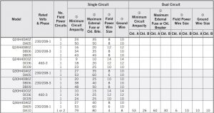
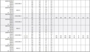
- These “Minimum Circuit Ampacity” values are to be used for sizing the field power conductors. Refer to the National Electrical code (latest version), Article 310 for power conductor sizing. CAUTION: When more than one field power circuit is run through one conduit, the conductors must be derated. Pay special attention to note 8 of Table 310 regarding Ampacity Adjustment Factors when more than three (3) current carryingconductors are in a raceway.
- Maximum size of the time delay fuse or circuit breaker for protection of field wiring conductors.
- Based on 75°copper wire. All wiring must conform to the National Electrical Code and all local codes.
- Maximum KW that can operate with the heat pump on is 9KW. Full heat available during emergency heat mode.
NOTE: The Maximum Overcurrent Protection (MOCP) value listed is the maximum value as per UL 1995 calculations for MOCP (branch-circuit conductor sizes in this chart are based on this MOCP). The actual factory-installed overcurrent protective device (circuit breaker) in thismodel may be lower than the maximum UL 1995 allowable MOCP value, but still above the UL 1995 minimum calculated value or Minimum Circuit Ampacity (MCA) listed.
IMPORTANT: While this electrical data is presented as a guide, it is important to electrically connect properly sized fuses and conductor wires in accordance with the National Electrical Code and all local codes.
References
[xyz-ips snippet=”download-snippet”]