![]()
INSTALLATION INSTRUCTIONS
I-TEC® Wall Sleeve for 1″ and 2″ LouversModels:IWS-A23IWS-B23IWS-C23

Getting Other Information and Publications
These publications can help with the installation of the air conditioner or heat pump. They can usually be found at the local library or purchased directly from the publisher. Be sure to consult the current edition of each standard.The standard for the Installation …………..ANSI/NFPA 90A of Air Conditioning and Ventilating SystemsStandard for Warm Air Heating ………..ANSI/NFPA 90B and Air Conditioning SystemsI-TEC Installation Instruction Manual… Bard/2100-549 (latest revision)
For more information, contact these publishers:
| ACCA | Air Conditioning Contractors of America 1712 New Hampshire Avenue, NWWashington, DC 20009Telephone: (202) 483-9370 Fax: (202) 234-4721 |
| ANY | American National Standards Institute 11 West Street, 13th FloorNew York, NY 10036Telephone: (212) 642-4900Fax: (212) 302-1286 |
| ASHRAE | American Society of Heating, Refrigerating, and Air Conditioning Engineers, Inc.1791 Tullie Circle, N.E.Atlanta, GA 30329-2305Telephone: (404) 636-8400Fax: (404) 321-5478 |
| BARD | Bard Manufacturing Company, Inc.1914 Randolph DriveBryan, OH 43506Telephone: (419) 636-1194Fax: (419) 636-2640 |
I-TEC WALL SLEEVE GENERAL INFORMATION
Shipping Damage
Upon receipt of equipment, the carton should be checked for external signs of shipping damage. If damage is found, the receiving party must contact the last carrier immediately, preferably in writing, requesting inspection by the carrier’s agent.
General
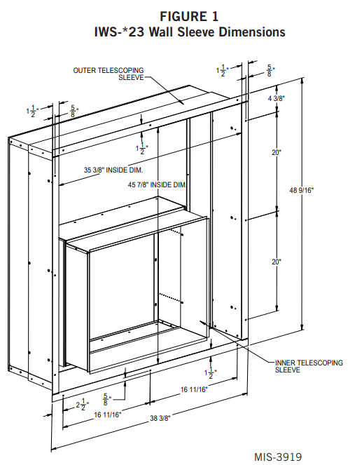
The IWS-*23 Series wall sleeve is designed for use with the I-TEC Series heat pump. The wall sleeve assembly consists of a large intake sleeve, smaller exhaust sleeve and an adapter curb. Both sleeves are telescoping to adjust for different wall depths. See Figures 1 and 2.
| Wall SleeveModel Number | Wall Thickness | Standard LouverDepth |
| IWS-A23 | 5.5″ – 8″ | 1″ |
| IWS-B23 | 8″ – 13.5″ | 1″ |
| IWS-C23 | 13″ – 23.5″ | 1″ |
The adapter curb is 7″ deep and allows the smaller sleeve to be used. When using this sleeve and adapter the unit will be 7″ from the indoor wall surface, and an ILST trim kit will be needed.These instructions explain the recommended method to install the wall sleeve. The equipment covered in this manual is to be installed by trained service and installation technicians.These instructions and any instructions packaged with any separate equipment required to make The entire air conditioning system should be carefully read before beginning the installation.
While intended as a general recommended guide, these instructions do not supersede any national and/or local codes in any way. Authorities having jurisdiction should be consulted before the installation is made.
Unpacking
- The smaller exhaust sleeve is attached to the weatherization plate with two (2) screws for shipping. Remove these screws (throw away) and set the exhaust sleeve assembly aside.
- Remove the inner telescoping sleeve (with the rubber gasket) from the larger inlet sleeve and set it aside.
- Remove inlet sleeve, with weatherization plate attached, from the carton and turn over.
- Remove and save the four (4) screws attaching the security plate.
Side Angle Relocation for ILA-2 Louver
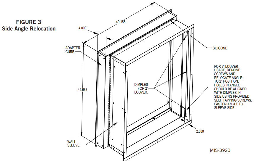
The IWS-*23 wall sleeve is designed for use with both 1″ and 2″ louver depths. As shipped, the sleeve is ready for 1″ louver installation. Refer to Figure 3 for angle installation instructions for 2″ louver depth.

Installation – Wood Framed Walls
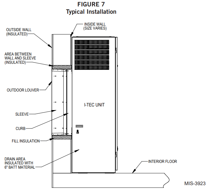
For wood frame construction walls, the minimum dimensions of the opening must be 48″ tall by 42¾” inches wide. A 2 x 6 header will be required for the opening. The sides of the opening must have trimmer studs to support the header and to provide a structural member on which to fasten the sleeve (see Figure 4).All of the dimensions are referenced from the finished floor height. If a riser platform accessory is used, adjust dimensions accordingly.Once the opening is framed, the sheeting can be installed; the sheeting material must not extend into the opening.The intake sleeve should be test fit into the opening to make sure of the dimensions. The sleeve must be inserted into the opening from the outside of thebuilding. The bottom of the sleeve must be level from side to side, and the sleeve must be square in the opening. A slope is built into the bottom of the sleeve from the inside to the outside. This will allow any water that gets into the sleeve to drain out. Once the test fit is completed, the sleeve must be removed from the opening, and two 1/4″ beads of the sealant must be applied to the mounting flanges of the sleeve (see Figure 5).The sleeve is then re-inserted into the prepared opening from the outside of the building. All of the mounting flanges must contact the exterior wall. Check to see that there is enough sealant to make this joint watertight. Additional sealant must be applied as necessary. The sleeve must be centered in the opening, and the bottom of the sleeve must be checked to make certain that it is level from side to side. The bottom flange should be secured to the wall by using two (2) field-supplied wood screws through the holes in the bottom mounting flange of the sleeve. The sleeve must be checked to make sure that it is square in the opening. Once the sleeve is square, the side and top mounting flanges of the sleeve must be secured to the wall with ten (10) field-supplied wood screws through the holes in the flanges.The inner portion of the intake sleeve must be inserted from the inside of the building. While holding the flanged side of the sleeve, slide it into the outer sleeve and insert far enough so it projects approximately ½” from either the smooth wall surface or from the sill.Final adjustment must be done from the outside.On the inside of the building, the gaps between the sleeve and the rough wall opening must be filled with insulation.NOTE: If foam insulation is used, the final location of the inner sleeve must be determined since the foam insulation could lock the inner sleeve into an incorrect location causing either an air leak between the sleeve and back of the unit or preventing the unit from going as tight to the wall or sill as desired. This must be done before the unit is placed and before the inner portion of the intake, sleeve is secured with screws to the outer sleeve.Insulating this space will prevent infiltration of any unwanted outside air (see Figure 7 on page 9).


If the I-TEC unit will be drained through the wall, the drain line must be installed prior to setting the unit.Information for the drain installation is provided in the main installation instructions manual supplied with the unit. At this point, the following are options:
- Install the weatherization plate if the I-TEC unit is not ready to be installed.NOTE: The exhaust sleeve attaches to the I-TEC unit. Store it and any remaining mounting hardware in a safe location.
- Proceed with the attachment of the wall sleeve to the I-TEC unit (see page 8).
Installation – Masonry Construction Walls
For masonry construction walls, the minimum dimensions for the opening will be 48″ tall by 42¾” wide. These dimensions are measured from the finished floor height (see Figure 6). These will be the finish dimensions of the opening.The sleeve should be test fit in the opening before final preparations are made. The sleeve will be installed into the opening from the outside of the building in. The sleeve must be centered in the opening from side to side. The mounting flanges of the sleeve must contact the outside wall all around the opening. The side and top mounting flanges must have the mounting holes drilled into the outside wall for the concrete anchors which will hold the sleeve in the wall.

The holes should be drilled through the holes in the sleeve with the sleeve level and square in the opening. A slope is built into the bottom of the sleeve from the inside to the outside. This will allow any water that gets into the sleeve to drain out. Once the test fitting has been checked out, the sleeve should be removed from the wall.With the sleeve removed, two 1/4″ beads of the sealant must be applied to the flanges that contact the outside wall (see Figure 5).The sleeve must be installed back in the wall making sure that the predrilled holes in the wall line up with the holes in the mounting flanges of the sleeve. Check to make sure that there is enough sealant between the wall and the flanges to make the joint watertight.Additional sealant must be applied as required. The sleeve must be anchored to the wall. All four mounting flanges must be fastened to the outside wall using twelve (12) field-supplied masonry screws.The inner portion of the intake sleeve must be inserted from the inside of the building. While holding the flanged side of the sleeve, slide it into the outer sleeve and insert far enough so it projects approximately ½” from either the smooth wall surface or from the sill.The final adjustment must be done from the outside.On the inside of the building, the gaps between the sleeve and the rough wall opening must be filled with insulation.
NOTE: If foam insulation is used, the final location of the inner sleeve must be determined since the foam insulation could lock the inner sleeve into an incorrect location causing either an air leak between the sleeve and back of the unit or preventing the unit from going as tight to the wall or sill as desired. This must be done before the unit is placed and before the inner portion of the intake, sleeve is secured with screws to the outer sleeve. Insulating this space will prevent infiltration of any unwanted outside air (see Figure 7).If the I-TEC unit will be drained through the wall, the drain line must be installed prior to setting the unit.Information for the drain installation is provided in the main installation instructions manual supplied with the unit. At this point, the following are options:
- Install the weatherization plate if the I-TEC unit is not ready to be installed.NOTE: The exhaust sleeve attaches to the I-TEC unit.Store it and any remaining mounting hardware in a safe location.
- Proceed with the attachment of wall sleeve to I-TEC unit.
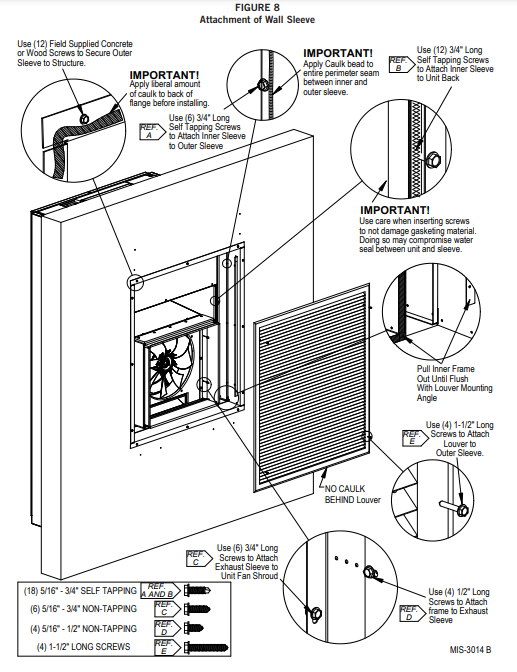
Attachment of Wall Sleeve to I-TEC Unit
Move the unit into place ensuring it is aligned side to side. Push it back until the side panels are flush with the wall, or until the sides contact the window sill—ifthat is the case. From the outside of the building, push the inner sleeve inward until the foam gasket contacts the unit. Attach the sleeve to the rear of the I-TEC using the twelve (12) ¾” long self-tapping screws supplied with the sleeve (see Figure 8, REF. B).Tie the inner and outer sleeves together with the three (3) ¾” long self-tapping screws on each side (see Figure 8, REF. A). Apply a bead of caulk to the entire perimeter seam between the inner and outer sleeves (see Figure 8, REF. A).The exhaust sleeve has three (3) screw slots in each side flange. Line these up with the screw engagement holes in the fan panel. Attach using six (6) ¾” long sheet metal screws supplied with the sleeve (see Figure 8, REF. C). Extend the sleeve out until it is flush with the louver attachment angles. Lock the sleeve in place using two (2) ½” long sheet metal screws on each side by shooting through the slot into a pre-punched hole (Figure 8, REF. D). Use 1-½” long screws supplied to attach louver to outer sleeve (See Figure 8, REF. E).
![]()
Bard Manufacturing Company, Inc.Bryan, Ohio 43506www.bardhvac.com
Manual: 2100-686BSupersedes: 2100-686ADate: 4-22-21
References
[xyz-ips snippet=”download-snippet”]