![]() Supplemental InstructionsModels:T36S1D, T42S1D, T48S1D, T60S1D
Supplemental InstructionsModels:T36S1D, T42S1D, T48S1D, T60S1D
This model provides a unique dehumidification circuit for periods of high indoor humidity conditions.Additionally an “energy recovery ventilator” may be provided to allow for outside ventilation air requirements by eliminating excessive sensible and latent loads as a result of the increased ventilation requirement.Refer to Specification Sheet S3447 for the standard features of the base unit. Electrical data for the dehumidification models is different than the electrical data for the standard T**S1 models. Refer to Page 7 for the electrical data.
Dehumidification Circuit
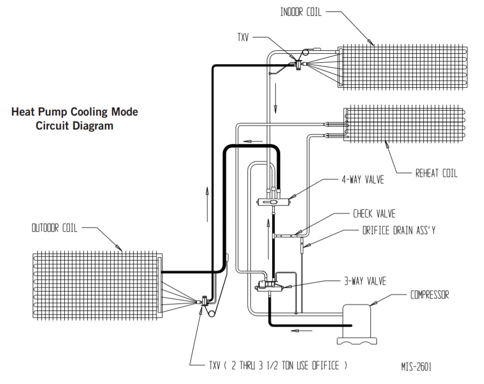
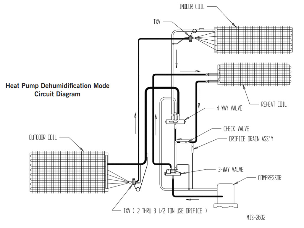
The dehumidification circuit incorporates an independent heat exchanger coil in the supply air stream in addition to the standard evaporator coil.This coil reheats the supply air after it passes over the cooling coil, and is sized to nominally match the sensible cooling capacity of the evaporator coil.Extended run times in dehumidification mode can be achieved using waste heat from the refrigeration cycle to achieve the reheating process, while at the same time large amounts of moisture can be extracted from the passing air stream. Models that also have electric heaters installed have the electric heat inhibited during dehumidification mode, although it remains available for additional reheat during certain conditions. See below for specific operating sequences, and see attached are tables for performance on sensible and latent capacities, water removal ratings, and supply air delivery conditions.The dehumidification refrigerant reheat circuit is controlled by a 3-way valve directing the refrigerant gas to the normal condenser during periods when standard air conditioning is required. During periods of time of low ambient temperature (approximately 65° to 75° outdoor) and high indoor humidity, a humidistat senses the need for mechanical dehumidification. It then energizes both the compressor circuit and the 3-way valve, thus directing the hot refrigerant discharge gas into a separate desuperheating condenser circuit which reheats the conditioned air before it is delivered to the room. The refrigerant gas is then routed from the desuperheating condenser to the system condenser for further heat transfer. A small orifice inserted betweenthe reheat coil return line and the suction line will prevent liquid from accumulating in the reheat coil when it is inactive. This drain does not affect the normal operation of the system. A check valve is located in the reheat coil return line. It has a soft spring to hold the ball on the seat. Refer to Page 3 for the location of the check valve and drain back orifice. When the humidistat is satisfied, the system automatically switches back to normal A/C mode and either continues to operate or turns off based on the signal from the wall thermostat. The result is separate humidity control at minimum operating cost.
Dehumidification Sequence of Operation
Dehumidification is controlled through the thermostat (if capable) or through a separate humidistat. On a call for dehumidification mode of operation, the compressor and 3-way valve that feeds the reheat coil are energized through circuit R-W3. Dehumidification will continue until the humidistat is satisfied. If the room temperature falls below 1 st stage heating setpoint, electric heat will be energized by the room thermostat and cycle to maintain room temperature.If the 2 and stage heating setpoint is reached, the dehumidification cycle is de-energized and the heat pump heating is energized.If the mixed air (return and ventilation, if used) temperature (measured at the internal filter location) drops below 65°F during the dehumidification cycle, electric heat will cycle to help maintain room temperature to the 65°F condition.Anytime there is a call for an R-Y circuit, dehumidification is canceled and the unit will operate until satisfied.If the dehumidification call is still present when the R-Y call is satisfied, the unit will continue to operate and revert to dehumidification mode.
 |
 |
| T36S1D Application Performance Data | ||||||||||
| IndoorConditions | Outdoor | System Capacity | Pounds ofWater/Hour | EvaporatorAirflow | ApproximateSupply Air | Mode | ||||
| DB/WB | % RH | DB | Total | Sensible | Latent | S/T | Lbs. | CFM | DB/WB | A/C vs. Dehum |
| 65/63 | 90 | 65 | 39,773 | 17,117 | 22,656 | 0.43 | 21.37 | 1100 | 51.3 / 51.0 | A/C |
| 65/63 | 90 | 65 | 20,483 | (-1,612) | 22,095 | 0 | 20.84 | 1100 | 66.2 / 57.5 | Dehum |
| 75/62.5 | 50 | 75 | 37,395 | 28,861 | 8,534 | 0.77 | 8.05 | 1100 | 51.4 / 50.6 | A/C |
| 75/62.5 | 50 | 75 | 13,111 | 6,588 | 6,523 | 0.5 | 6.15 | 1100 | 69.6 / 58.6 | Dehum |
| 75/65.5 | 60 | 75 | 39,695 | 25,159 | 14,536 | 0.63 | 13.71 | 1100 | 54.5 / 53.9 | A/C |
| 75/65.5 | 60 | 75 | 17,009 | 3,586 | 13,423 | 0.21 | 12.66 | 1100 | 72.0 / 60.9 | Dehum |
| 75/68 | 70 | 75 | 41,414 | 22,024 | 19,390 | 0.53 | 18.29 | 1100 | 57.1 / 56.6 | A/C |
| 75/68 | 70 | 75 | 18,168 | 957 | 17,211 | 0.05 | 16.24 | 1100 | 74.2 / 63.6 | Dehum |
| 80/67 | 50 | 95 | 2,594 | (-487) | 3,082 | 0 | 2.91 | 1100 | 80.4 / 66.2 | Dehum |
| T42S1D Application Performance Data | ||||||||||
| IndoorConditions | Outdoor | System Capacity | Pounds ofWater/Hour | EvaporatorAirflow | ApproximateSupply Air | Mode | ||||
| DB/WB | % RH | DB | Total | Sensible | Latent | S/T | Lbs. | CFM | DB/WB | A/C vs. Dehum |
| 65/63 | 90 | 65 | 44,438 | 18,907 | 25,531 | 0.43 | 24.09 | 1100 | 51.8 / 51.2 | A/C |
| 65/63 | 90 | 65 | 20,765 | (-587) | 21,352 | 0 | 20.14 | 1100 | 65.5 / 57.9 | Dehum |
| 75/62.5 | 50 | 75 | 40,262 | 31,532 | 8,730 | 0.78 | 8.24 | 1100 | 52.3 / 51.2 | A/C |
| 75/62.5 | 50 | 75 | 13,136 | 7,555 | 5,581 | 0.58 | 5.27 | 1100 | 69.8 / 59.1 | Dehum |
| 75/65.5 | 60 | 75 | 42,824 | 27,116 | 15,708 | 0.63 | 14.82 | 1100 | 55.4 / 54.4 | A/C |
| 75/65.5 | 60 | 75 | 15,544 | 4,489 | 11,055 | 0.29 | 10.43 | 1100 | 71.8 / 61.8 | Dehum |
| 75/68 | 70 | 75 | 45,445 | 24,140 | 21,305 | 0.53 | 20.1 | 1100 | 57.9 / 57.1 | A/C |
| 75/68 | 70 | 75 | 19,977 | 1,667 | 18,310 | 0.08 | 17.27 | 1100 | 73.9 / 63.6 | Dehum |
| 80/67 | 50 | 95 | 5,289 | (-216) | 5,505 | 0 | 5.19 | 1100 | 80.2 / 65.7 | Dehum |
Values shown in ( ) are BTUH of heat available at these conditions
| T48S1D Application Performance Data | ||||||||||
| IndoorConditions | Outdoor | System Capacity | Pounds ofWater/Hour | EvaporatorAirflow | ApproximateSupply Air | Mode | ||||
| DB/WB | % RH | DB | Total | Sensible | Latent | S/T | Lbs. | CFM | DB/WB | A/C vs. Dehum |
| 65/63 | 90 | 65 | 53,748 | 22,691 | 31,057 | 0.42 | 29.3 | 1100 | 51.9 / 51.4 | A/C |
| 65/63 | 90 | 65 | 28,218 | (-1,638) | 29,856 | 0 | 28.17 | 1100 | 66.1 / 57.3 | Dehum |
| 75/62.5 | 50 | 75 | 49,295 | 38,697 | 10,598 | 0.79 | 10 | 1100 | 52.5 / 51.6 | A/C |
| 75/62.5 | 50 | 75 | 20,207 | 9,819 | 10,388 | 0.49 | 9.8 | 1100 | 69.3 / 58.3 | Dehum |
| 75/65.5 | 60 | 75 | 52,392 | 33,593 | 18,799 | 0.64 | 17.73 | 1100 | 55.5 / 54.7 | A/C |
| 75/65.5 | 60 | 75 | 24,015 | 5,714 | 18,301 | 0.24 | 17.27 | 1100 | 71.7 / 60.9 | Dehum |
| 75/68 | 70 | 75 | 55,457 | 29,604 | 25,853 | 0.53 | 24.39 | 1100 | 57.8 / 57.1 | A/C |
| 75/68 | 70 | 75 | 27,428 | 2,150 | 25,278 | 0.08 | 23.85 | 1100 | 73.7 / 63.0 | Dehum |
| 80/67 | 50 | 95 | 11,243 | 1,576 | 9,667 | 0.14 | 9.12 | 1100 | 79.1 / 64.9 | Dehum |
| T60S1D Application Performance Data | ||||||||||
| IndoorConditions | Outdoor | System Capacity | Pounds ofWater/Hour | EvaporatorAirflow | ApproximateSupply Air | Mode | ||||
| DB/WB | % RH | DB | Total | Sensible | Latent | S/T | Lbs. | CFM | DB/WB | A/C vs. Dehum |
| 65/63 | 90 | 65 | 62,312 | 27,363 | 34,949 | 0.44 | 32.97 | 1650 | 50.1 / 49.9 | A/C |
| 65/63 | 90 | 65 | 33,100 | (-289) | 33,389 | 0 | 31.5 | 1650 | 65.2 / 56.6 | Dehum |
| 75/62.5 | 50 | 75 | 57,542 | 44,209 | 13,333 | 0.77 | 12.58 | 1650 | 51.0 / 50.1 | A/C |
| 75/62.5 | 50 | 75 | 26,138 | 12,483 | 13,655 | 0.48 | 12.88 | 1650 | 68.2 / 57.2 | Dehum |
| 75/65.5 | 60 | 75 | 61,912 | 38,922 | 22,990 | 0.63 | 21.69 | 1650 | 53.7 / 53.2 | A/C |
| 75/65.5 | 60 | 75 | 30,827 | 7,749 | 23,078 | 0.25 | 21.77 | 1650 | 70.8 / 59.8 | Dehum |
| 75/68 | 70 | 75 | 65,315 | 34,612 | 30,703 | 0.53 | 28.97 | 1650 | 56.0 / 55.6 | A/C |
| 75/68 | 70 | 75 | 34,303 | 3,483 | 30,820 | 0.1 | 29.08 | 1650 | 73.0 / 62.1 | Dehum |
| 80/67 | 50 | 95 | 17,289 | 2,543 | 14,746 | 0.15 | 13.91 | 1650 | 78.5 / 63.9 | Dehum |
Values shown in ( ) are BTUH of heat available at these conditions
TABLE 1Dehumidification Relay Logic Board
| Energize on UnitTerminal Strip | Mode | Occupied/Unoccupied | Inputs to the Board | Outputs from the Board | ||||||||||
| RAT | Y | B | W2 | Al | D | G | G1 | BK | RV | TWV | W | YO | A2 | |
| Y, G | 1st Cooling | Unoccupied | X | X | X | X | X | |||||||
| Y, G, 01 | 1st Cooling | Occupied | X | X | X | X | X | X | X | |||||
| Y, G, W3, 01 | 1st Cool/Dehum | Occupied | X | X | X | X | X | X | X | X | ||||
| Y, G, W3 | 1st Cool/Dehum | Unoccupied | X | X | X | X | X | X | ||||||
| Y, Yl*, G | 2nd Cooling | Unoccupied | X | X | X | X | X | |||||||
| Y, Yl*, G, 01 | 2nd Cooling | Occupied | X | X | X | X | X | X | X | |||||
| Y, Yl*, G, 01, W3 | 2nd Cool/Dehum | Occupied | X | X | X | X | X | X | X | X | ||||
| Y, Y1*, G, W3 | 2nd Cool/Dehum | Unoccupied | X | X | X | X | X | X | ||||||
| Y, G, B | 1st Heating | Unoccupied | X | X | X | X | X | X | X | |||||
| Y, G, B, 01 | 1st Heating | Occupied | X | X | X | X | X | X | X | X | X | |||
| Y, G, B, 01, W3 | 1st Heat/Dehum | Occupied | X | X | X | X | X | X | X | X | X | X | X | |
| V, G, B, W3 | 1st Heat/Dehum | Unoccupied | X | X | X | X | X | X | X | X | ||||
| V, Yl*, B, G | 2nd Heating | Unoccupied | X | X | X | X | X | X | X | |||||
| Y, Y1*, B, G, 01 | 2nd Heating | Occupied | X | X | X | X | X | X | X | X | X | |||
| Y, Yl*, B, G, 01, W3 | 2nd Heat/Dehum | Occupied | X | X | X | X | X | X | X | X | X | X | X | |
| Y, Y1*, B, G, W3 | 2nd Heat/Dehum | Unoccupied | X | X | X | X | X | X | X | X | ||||
| Y, Y1*, G, B, W2 | 3rd Heating ** | Unoccupied | X | X | X | X | X | X | X | X | X | |||
| Y, Yl*, G, B, W2, 01 | 3rd Heating ** | Occupied | X | X | X | X | X | X | X | X | X | X | X | |
| Y, Yl*, G, B, W2, 01, W3 | 3rd Heating ** | Occupied | X | X | X | X | X | X | X | X | X | X | X | X |
| Y, yr, G, B, W2, W3 | 3rd Heating ** | Unoccupied | X | X | X | X | X | X | X | X | X | X | ||
| B, W2, E***, G | Emergency Heat | Unoccupied | X | X | X | X | X | X | X | |||||
| B, W2, E***, G, 01 | Emergency Heat | Occupied | X | X | X | X | X | X | X | X | X | |||
| B, W2, E***. G, 01, W3 | Emergency Heat/Dehum | Occupied | X | X | X | X | X | X | X | X | X | |||
| B, W2, E***, G, W3 | Emergency Heat/Dehum | Unoccupied | X | X | X | X | X | X | X | |||||
| W3 | Dehum | Unoccupied | X | X | X | X | ||||||||
| W3, 01 | Dehum | Occupied | X | X | X | X | X | X | ||||||
| W3, 01, RAT Closed | Dehum/RAT | Occupied | X | X | X | X | X | X | X | X | X | |||
| W3, RAT Closed | Dehum/RAT | Unoccupied | X | X | X | X | X | X | X |
* Y1 directly energizes the compressor solenoid; it does not go through the dehum board.** Is only applicable to units with strip heat.*** Is directly energized at the terminal strip of the unit; it does not go through the dehum board.
TABLE 2Electrical Specifications
- These “Minimum Circuit Ampacity” values are to be used for sizing the field power conductors. Refer to the National Electrical Code (latest version), Article 310 for power conductor sizing.CAUTION: When more than one field power circuit is run through one conduit, the conductors must be derated. Pay specialattention to note 8 of Table 310 regarding Ampacity Adjustment Factors when more than three (3) current-carrying conductors are in a raceway.
- Maximum size of the time delay fuse or circuit breaker for protection of field wiring conductors.
- Based on 75°copper wire. All wiring must conform to the National Electrical Code and all local codes.
- The maximum KW that can operate with the heat pump on is 4KW. Full heat available during emergency heat mode.
- The maximum KW that can operate with the heat pump on is 10KW. Full heat available during emergency heat mode.
- The maximum KW that can operate with the heat pump on is 9KW. Full heat available during emergency heat mode.
- The maximum KW that can operate with the heat pump on is 8KW. Full heat available during emergency heat mode.
NOTE: The Maximum Overcurrent Protection (MOCP) value listed is the maximum value as per UL 1995 calculations for MOCP (branch-circuit conductor sizes in this chart are based on this MOCP). The actual factory-installed overcurrent protective device (circuit breaker) in this model may be lower than the maximum UL 1995 allowable MOCP value, but still above the UL 1995 minimum calculated value or Minimum Circuit Ampacity (MCA) listed.
IMPORTANT: While this electrical data is presented as a guide, it is important to electrically connect properly sized the fuses and conductor wires in accordance with the National Electrical Code and all local codes.
![]() Bard Manufacturing Company, Inc.Bryan, Ohio 43506www.bardhvac.comManual: 7960-640ESupersedes: 7960-640DDate: 5-14-21
Bard Manufacturing Company, Inc.Bryan, Ohio 43506www.bardhvac.comManual: 7960-640ESupersedes: 7960-640DDate: 5-14-21
References
[xyz-ips snippet=”download-snippet”]