
Bard W42-72AC/42-60HC UV-C LED Field Kits
WARNING
Electrical shock hazard.Disconnect the remote electric power supply or supplies before servicing. Failure to do so can result in serious injury or death.
Exposed moving parts.Disconnect all electrical power before servicing. Failure to do so can result in severe injury or amputation.
CAUTION
Sharp metallic edges.Take care and wear appropriate protective devices to avoid accidental contact with sharp edges. Failure to do so can result in personal injury. Ultraviolet band C (UV-C) energy may cause damage to non-metallic components except for UV-rated and HVAC-style drain pans. Select mounting locations that prevent exposure to vulnerable components. If mounting locations are limited, protect components with UV-resistant material such as aluminum foil, aluminum duct tape, metallic shields, etc.
WARNING
UV-C exposure can cause burns to skin and damage eyes. Ensure proper safety precautions are taken during installation. A trained, experienced technician must install the UV-C field kit.
CAUTION
UV radiation hazard.Use only with shielding in place. Protect eyes and skin from exposure to UV light.
Product Specifications
| Model | |
| Olympia UV-C Light F15T5-15W-UVC-DL | |
| Electrical Specs | |
| Input Voltage | 120-277VAC |
| Power Consumption | 15W |
| Frequency | 50/60Hz |
| Dimensional Specs | |
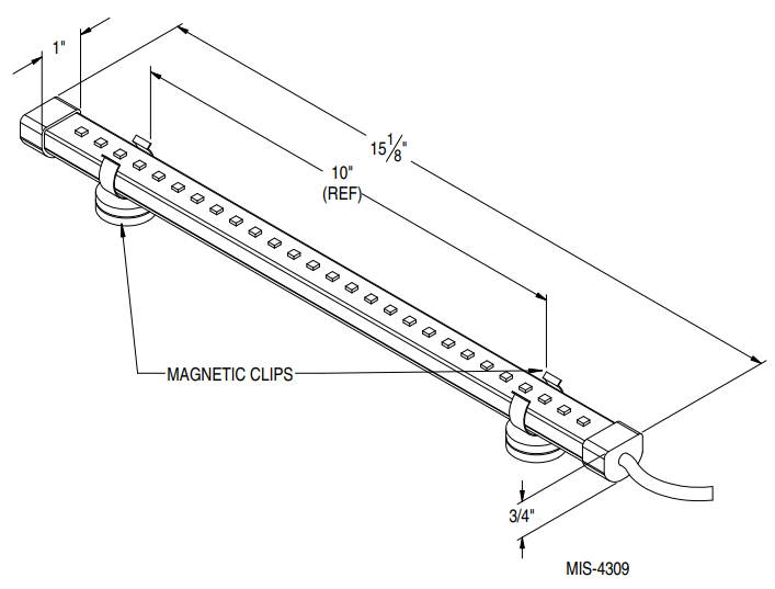
| Unit Dimensions | 15-1/8″ L x 3/4″ H x 1″ D |
| Weight | 1 lb |
| Performance | |
| Irradiance | 170µW/cm2 |
| UL Listing and Certifications | |
|
Compliance and Certifications |
UL 1598 |
| CSA C22.2#250.0 | |
| UL 8750 | |
| UL 2043 | |
| CE | |
| RoHS Directive | |
| “UV-C LED Light Bar Installed” Label 7961-622-0375 is located near unit serial plate |
Overview
The UV-C field-installed light kits utilize UV-C LED lighting technology to sterilize and improve overall air quality within an occupied space. UV-C exposure is proven to damage the DNA of microorganisms and render them inactive aiding in preventing the spread of diseases. These instructions are applicable to the following models:
| Kit | Voltage | Wall-Mount Models |
| 8620-343 | 460V | W42AC-72AC W42HC-60HC |
| 8620-344 | 230V |
Personal Protective Equipment (PPE)UV radiation is absorbed by clothing, plastic or glass. Once absorbed, the UV radiation is no longer active. Wear UV goggles or face shield. Cover any exposed skin with coats, gloves, etc.
UV-C band light spectrum is not visible to the eye.NOTE: The health aspects associated with the use of this product and its ability to aid in disinfection of environmental air have not been investigated by UL.NOTE: Color shift or chalking may occur without affecting structural properties.
Dimensions
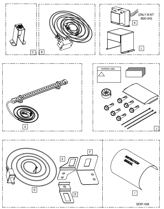
Parts List
| Reference Letter | Bard P/N | Description | Qty. |
| A | 910-2181 | 15″ UV-C Assembly | 1 |
| B | 910-2182 | Relay Assembly | 1 |
| C | 910-2183 | Red Indicator Light Assembly | 1 |
| D | 910-2184 | Door Panel Switch Assembly (Interlock Safety Device) | 1 |
| E | 113-908 | Bracket (WH/Q-TEC Q**H/A4 Units) | 1 |
| F | 113-909 | Bracket (I-TEC Units) | 1 |
| G | 113-913 | Bracket (Q-TEC Units) | 1 |
| H | 7961-963 | UV-C Warning Label | 1 |
| I | Per Model | Supplemental Instructions Manuals and Wire Diagrams | 4/2 |
| J | 400-0467 | Parts Bag – Six (6) Screws, Three (3) Zip Ties, Six (6) Pieces of Foil Tape, Bushing, UV-C Warning Label and “UV-C LED Light Bar Installed” Label | 1 |
| K | 910-2191 | 460V Stepdown Transformer Assembly (820-343 Kit Only) | 1 |
| L | 113-932 | Transformer Enclosure (820-343 Kit Only) | 1 |
Installation
Field-supplied tools needed:
- Appropriate personal protection equipment, including gloves and safety glasses
- Electrical meter to verify power status
- Drill
- Phillips head screwdriver
- 5/16″ nut driver
Installation Procedure
- Disconnect all power to HVACR unit. Use the meter to verify that power has been disconnected.
- Remove outer and inner control panel covers.
- Remove blower housing cover (large upper panel).
- Attach two (2) magnetic clips to the UV light assembly (see Dimensions drawing on page 2).
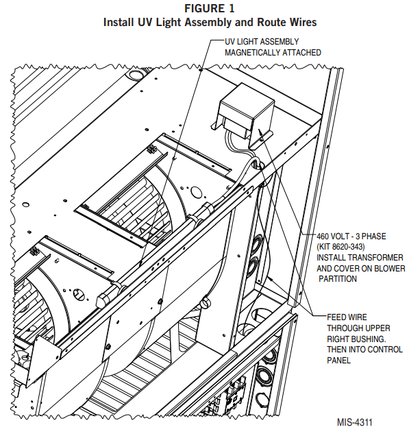
- Install UV light assembly onto blower partition on the inside of the front flange as shown in Figure 1. UV light should be directed over blower outlets, facing evaporator coil.
- Route wires into control panel through upper right bushing in blower partition, then into control panel as shown in Figure 1.
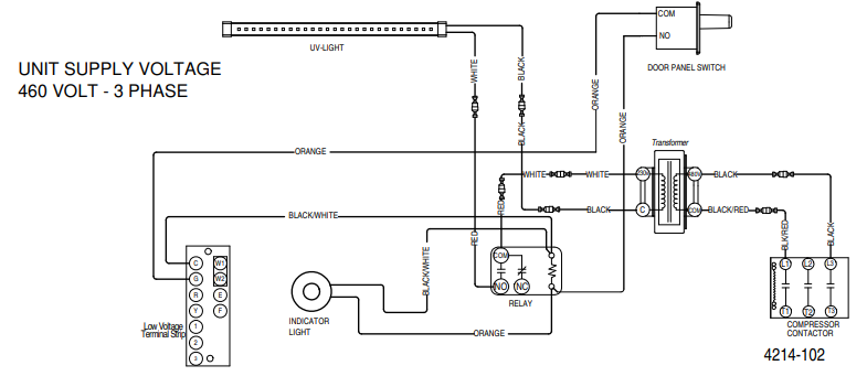
- Kit 8620-343 (460V-3PH Units) Only: Install 460V stepdown transformer on blower partition and route wires through blower partition as shown in Figure 1.

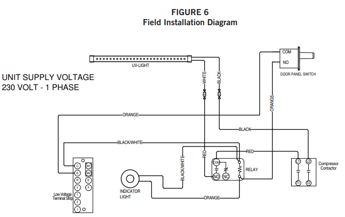
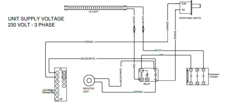
- Connect red wire from UV light assembly to “NO” contact on the relay assembly (see Field Installation Diagram on page 8).
- Determine unit supply voltage—located on the unit serial plate. Connect black wire from UV light assembly to:
- (230V-1PH) − “L2”
- (230V-3PH) − “L3”
- (460V-3PH) − Black Wire-TransformerSee Field Installation Diagram on page 8.
- Connect red wire from “COM” on relay assembly to:
- (230V-1PH) − “L1”
- (230V-3PH) − “L1”
- (460V-3PH) − White Wire-Transformer
- Connect short orange wire from relay assembly to indicator light assembly.
- Connect short black/white wire from relay assembly to indicator light.
- Control panel assemblies vary due to available control options. Find unused space on control panel and install relay and indicator light assemblies in control panel using self-drilling screws provided (see Figure 2).
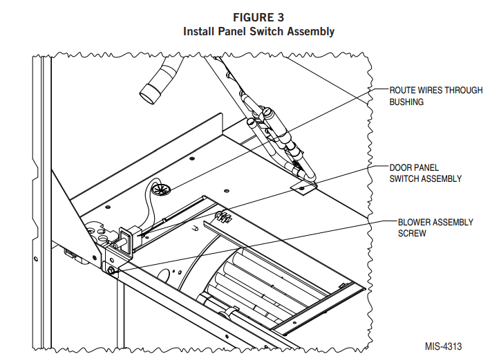
- Install the door panel switch into panel switch bracket 113-908 (see Figure 3). The door panel switch acts as an interlock safety device to disable the UV light source upon removal of the blower access panel preventing UV exposure.
- Remove the right screw from the blower assembly (see Figure 3). Do NOT discard the screw as it will be reinstalled.
- Install panel switch bracket directly behind blower mounting angle where the screw was removed (see Figure 3). Align the bottom hole in the bracket with a hole where the screw was removed in Step 13.
- Re-install screw to secure the blower assembly and panel switch assembly.
- Remove left filter and filter slide, then route long orange wire from relay assembly (up to door panel switch) and connect to “NO”. Route wire from door panel switch (down to control panel) through upper right control panel bushing, through filter partition housing and blower partition as shown in Figure 4.
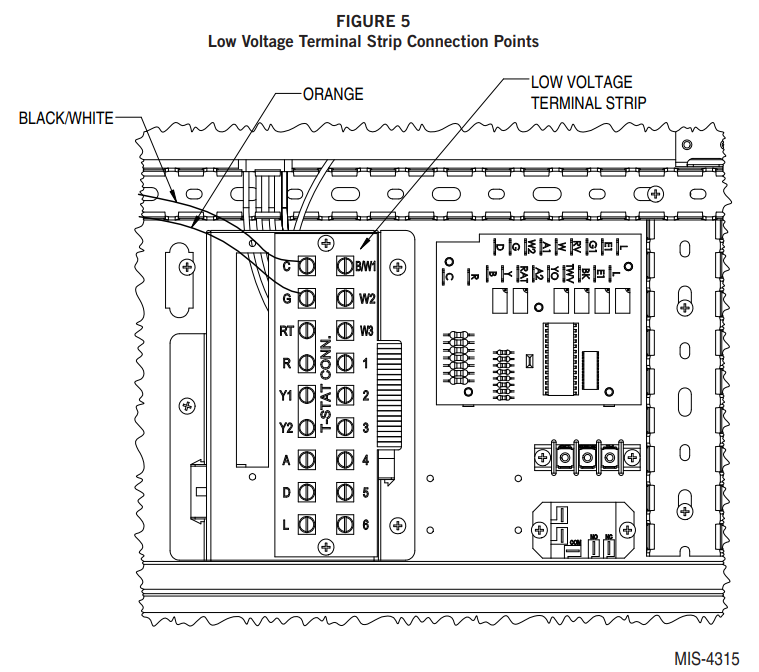
- Seat spade end of orange wire from the panel switch assembly under the “G” terminal on the low voltage strip assembly, then seat spade end of black/white wire from coil on the relay assembly under the “C” terminal on low voltage strip (see Figure 5).
- Wires can be dressed in provided zip ties or by tucking into wire channels. Ensure wires are secured away from sharp edges and moving parts to prevent damage. Cover wires and plastic components within a distance of 6″ of the UV light with foil tape to create a protective barrier from the UV light.
- UV light will not function without the blower panel installed because of the panel switch (interlock safety switch). Do NOT press the door panel switch with the blower panel removed as the UV source could become active and create UV exposure. Replace the blower access cover (large upper panel). Adhere UV-C Warning Label 7961-963 to blower access panel. Adhere “UV-C LED Light Bar Installed” Label 7961-622-0375 to the unit serial plate. (Serial plate is silver and located on the exterior of the unit cabinet or on a service panel with “5253-039- XXXX” printed in the lower right corner.).
- Now that the blower panel is installed, UV light operation can be safely verified. Restore power to unit and provide a “G” call signal from the thermostat. The operation can be confirmed if indicator light installed in Step 8 is ON in the control panel. Do NOT attempt to look at the UV source to confirm operation!
- Disconnect power to unit. Replace all inner and outer panel covers.
- Restore power to the unit.

 The door panel switch acts as an interlock safety device to disable the UV light source upon removal of the blower access panel preventing UV exposure.
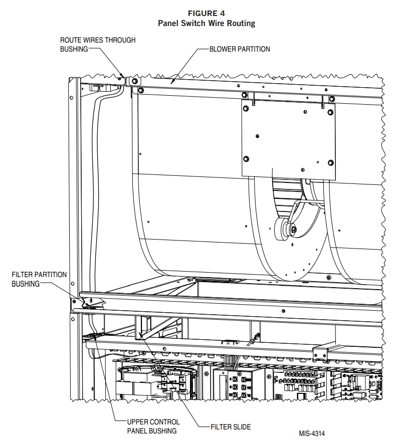
Bard Manufacturing Company, Inc.Bryan, Ohio 43506www.bardhvac.com
References
[xyz-ips snippet=”download-snippet”]