![]()
SUPPLEMENTAL INSTRUCTIONS
CMC-35 Alarm Relay Kit
The CMC-35 is a field-installable alarm relay kit. This alarm relay kit is only for use on R-410A refrigerant systems.The CMC-35 kit is for use with Bard models W42AC, W42HC, W48AC, W48HC, W60AC, W60HC, and W72AC wall-mount units.The CMC-35 kit consists of:
- 7960-857 Supplemental Instructions
- 910-2069 Relay Assembly
- 1012-065 Screws (2)
- 7961-312-0514 CMC-35 Unit I.D. Label
Field-supplied tools needed:
- Appropriate personal protection equipment, including gloves and safety glasses
- 5/16″ nut driver
- Phillips head screwdriver
- Small flat-head screwdriver for securing the wire in terminal blocks
- Electrical tools
- Multimeter for troubleshooting
 WARNING Electrical shock hazard. Disconnect the remote electric power supply or supplies before servicing. Failure to do so can result in serious injury or death.WARNING Exposed moving parts. Disconnect all electrical power before servicing. Failure to do so can result in severe injury or amputation. CAUTIONSharp metallic edges. Take care and wear appropriate protective devices to avoid accidental contact with sharp edges. Failure to do so can result in personal injury.
Installation
Disconnect all power to the wall-mount unit. Remove outer and inner control panel covers.
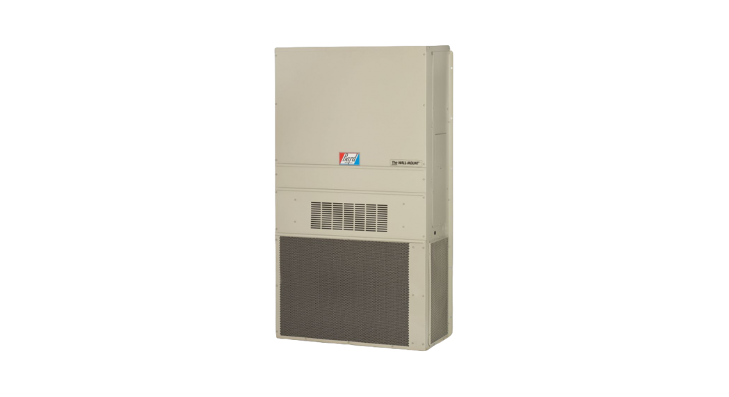
- Mount the 910-2069 relay assembly in the control panel as shown in Figure 1.
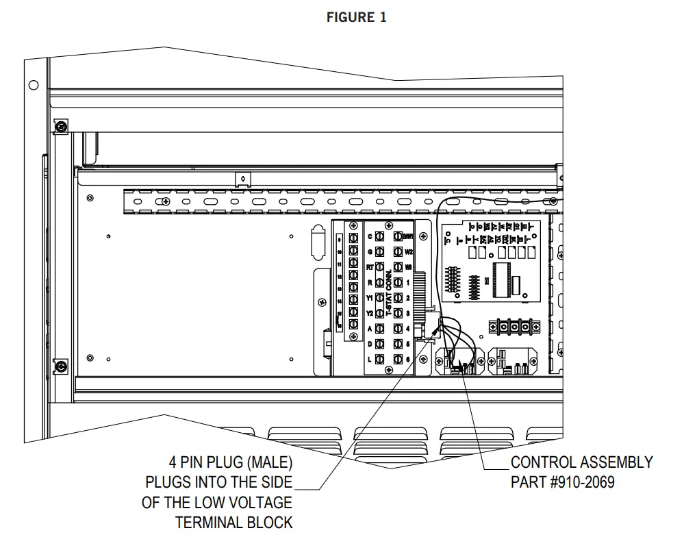
- Route the wires in the cable duct. Connect the 4 pin male plug to the female plug on the side of the low voltage terminal box. For air conditioners, connect the pink wire to the ALR terminal on the compressor control module. For heat pumps, connect the pink wire to the L terminal on the defrost logic board. Refer to Figure 2 on page 3 or the unit wiring diagram for proper wire connection locations.
- Make the desired dry contact connections on the front of the low voltage terminal strip. (Normally Closed = 1 & 3, or Normally Open = 2 & 3). See Figure 2 or the unit wiring diagram.
- Apply the “This unit is equipped with CMC-35 control module” label to the inside of the inner control panel cover above the unit wiring diagram.
- Replace the inner and outer control panel covers. This completes the installation.
Sequence of Operation
When installed, the alarm relay will indicate one of the following has occurred:
- High refrigerant pressure lockout
- Low refrigerant pressure lockout
- Unit power brownout lockout
During any of the listed events, an alarm can be signaled to a thermostat or controlling device. The unit will remain in lockout mode until the call for cooling is removed (Y1, Y2) or power is reset to the unit.
![]()
Bard Manufacturing Company, Inc.Bryan, Ohio 43506www.bardhvac.com
Manual: 7960-857ASupersedes: 7960-857Date: 3-18-21
References
[xyz-ips snippet=”download-snippet”]