
BEAM IsatDock DRIVE User Guide
BEAM Communications5/8 Anzed Court, MulgraveVictoria, 3170, AUSTRALIA
Tel: +61 3 8588 4500 Fax: +61 3 9560 9055
Information: [email protected]Support: [email protected]
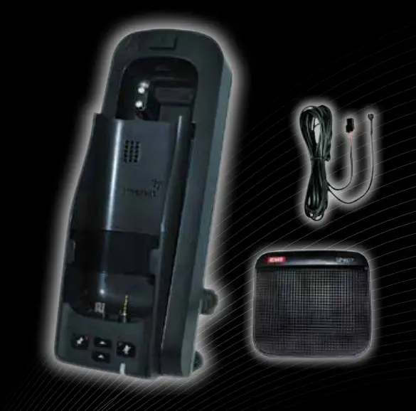
IsatDock DRIVE Equipment Overview
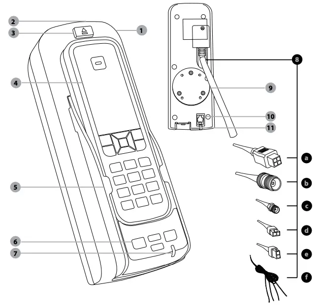
- IsatDock DRIVE unit
- Key Lock
- IsatPhone Eject Button
- IsatPhone Pro (not included)
- IsatPhone Pro Docking Tray
- Function Buttons
- Status Indication Light
- Power Cable Looma. Power Supplyb. Satellite TNC-Female Connectorc. GPS SMA-Female Connectord. Microphonee. Speakerf. Alert Loop (green & brown) Horn Alert (blue) Radio Mute (white)
- RAM Mounting
- Privacy Handset Connection
- Micro USB Data Connection
Specification Summary
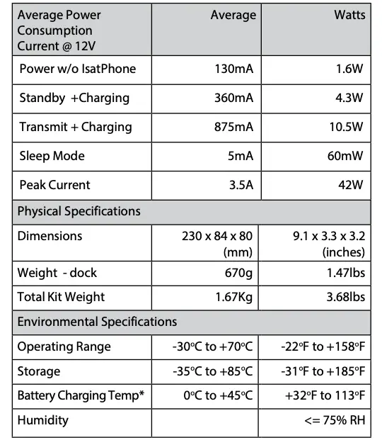
* It is ideal for the ambient temperature to be approximately 18 degrees below the 45°C upper limit for the handset to charge the battery whilst docked.
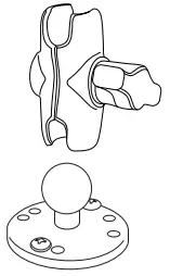
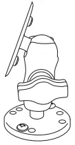
Mounting Cradle
The IsatDock DRIVE is supplied with a universal RAM® mount bracket that enables mounting to any flat surface (vertical or horizontal) within a vehicle, or other required location.
- Attach one pivot base to the rear of the IsatDock DRIVE using the M4 screws and washers supplied.

- Secure the second pivot base to the location you have selected for mounting the IsatDock DRIVE. (screws not supplied)
- Use the interconnecting step of the RAM® mount to secure the IsatDock DRIVE to the pivot base and tighten into the desired location firmly using the wing nut on the stem.
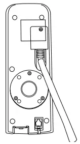
Inmarsat Antenna Connection

The antenna connections exit from the rear of the IsatDock DRIVE cradle, via the antenna loom. There are two RF connections required, the Satellite TNC – Female Connector and GPS SMA-Female connector.
- Refer to the antennas installation guide for antenna mounting and location requirements.
- Connect the antenna cable labelled “Inmarsat” to the IsatDock’s TNC connector
- Connect the antenna cable labelled “GPS” to the IsatDock’s SMA connector
- Connect the antenna cable labelled “Inmarsat” to the antenna connector labelled “ISAT” via the SMA connector.
- Connect the antenna cable labelled “GPS” to the antenna connector labelled “GPS” via the SMA connector
![]()
WARNING
DO NOT pull with force on the cables from the rear of the IsatDock DRIVE. Please install strain relief clamping for the antenna cables where required.
Correct installation of the antenna system is a vital part of the IsatDock DRIVE system, to ensure reliable functionality, and drop-free calls.
WARNING
Changes or modifications not expressly approved by BEAM Communications could void the product warranty
WARNING
To satisfy FCC RF exposure requirements for mobile transmitting devices, a separation distance of 55 cm or more should be maintained between the antenna of this device and persons during device operation. To ensure compliance, operations at closer than this distance is not recommended.
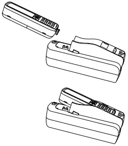
Docking and Un-docking your IsatPhone Pro
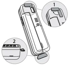
To place the IsatPro Phone into the docking unit, both the ‘covers’ on the external antenna connectors and the USB/Audio connectors need to be opened.
- The antenna ‘cover’ must be placed at 90 degrees to the antenna connector cavity and run parallel to the top edge of the phone.
- The ‘cover’ in the base of the phone should be in the a 90 degree opened position.
- To dock the handset, align the IsatPhone with the phone tray and slide the handset down until it seats flush to the bottom of the tray. Swing the phone down into the cradle by applying pressure to the top of the handset. An audible ‘click’ is heard when the phone is in the docked position.
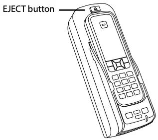
- To remove the handset from the cradle, press the EJECT button at the top of the docking station. The dock will swing out and the handset can be removed.
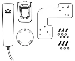
Privacy Handset (Optional – Extra Order)
The IsatDock DRIVE provides a RJ9 audio socket on the bottom of the docking unit, for connection to the Beam privacy handset. This provides a local handset function, conveniently mounted next to the IsatDock DRIVE cradle.
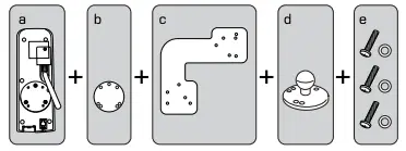
- The Privacy Handset Kit (purchased/ ordered separately) contains a mounting bracket, space plate, screws, washers and nut bolts.
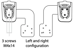
- Mount the handset cup to the mounting plate, it can be installed to the left or right side of the dock by simply rotating the bracket. Secure the cup with the washer and nut bolt behind the bracket.
- Mount the spacer plate and the mounting bracket to the rear of the IsatDock DRIVE, by using the longer screws provided with the kit. The original RAM® arm-bracket plate is also reinstalled behind these plates.[a] Rear of IsatDock[b] Spacer[c] Mounting plate[d] RAM base[e] Mounting screws and washers
- Plug the Privacy Handset RJ9 connector into the bottom of the docking unit, as per image below.
 [a] Rear of IsatDock[b] Spacer[c] Mounting plate[d] RAM base[e] Mounting screws and washers
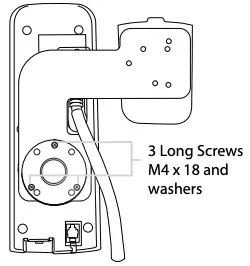
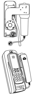
Privacy Handset mode is enabled when the handset is removed from the cup. Please ensure to re-dock the Privacy Handset when not in use.
IsatDock DRIVE Front Panel
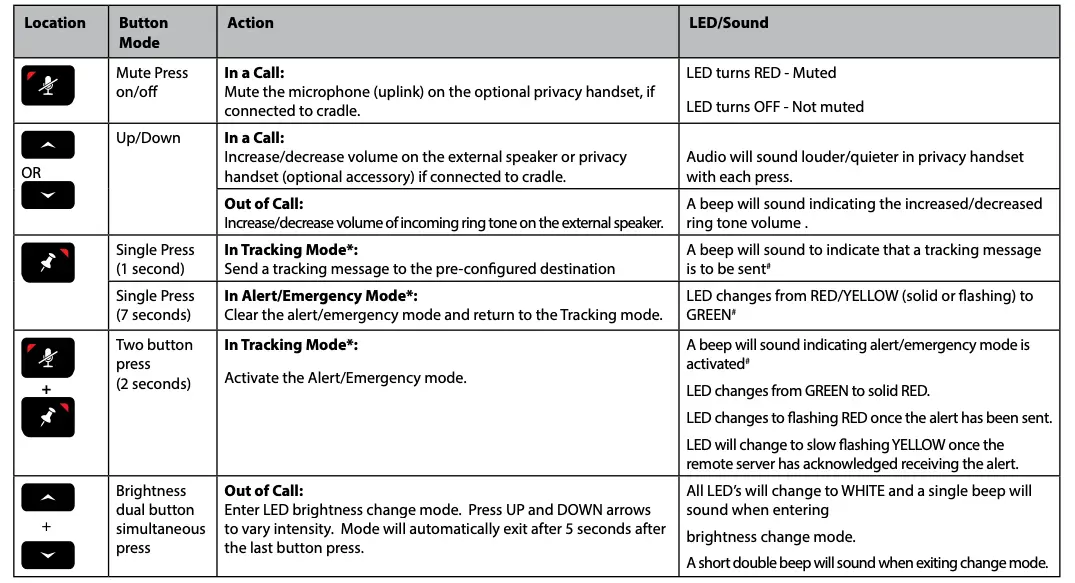
* This action is optional, only when the Tracking Mode for your IsatDock DRIVE is configured and activated.# A beep will only sound if audible alerts are enabled in the Falcon
References
[xyz-ips snippet=”download-snippet”]