BEAM ISD2MARINE Basic Piracy Bundle
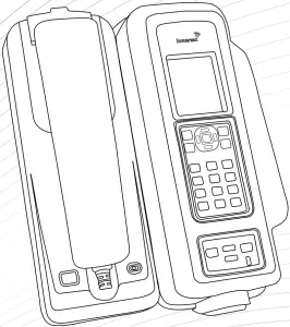
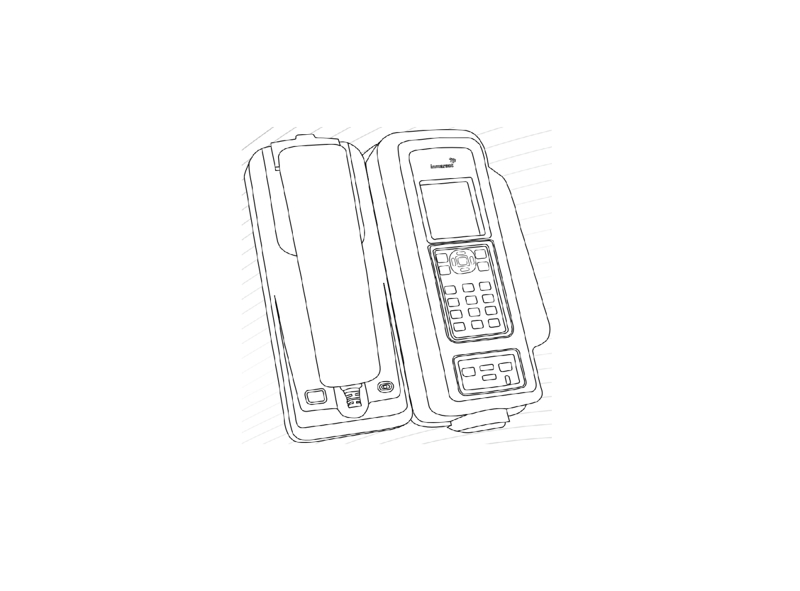
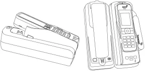
IsatDock2 MARINE Equipment Overview

- Cover Lock Clasp
- Marine Cover
- Mounting Cup (spring or springless cup options)
- Privacy Handset
- Speaker (under handset)
- Microphone
- Speakerphone Button
- Cover Seal
- IsatPhone 2 Eject Button
- IsatPhone 2 (not included)
- Function Buttons
- Status Indication LED
- Back Panel Connectorsa. USB Data Interfaceb. BEAM Alert Loop connectionc. RJ11/POTS interfaced. DC power and accessory inpute. RJ9 Privacy handset
- IsatDock2 Adapter
Specification Summary
| Average Power Consumption Current @ 12V | Average | Watts |
| Power w/o IsatPhone 2 | 130mA | 1.6W |
| Standby + Charging | 360mA | 4.3W |
| Transmit + Charging | 875mA | 10.5W |
| Sleep Mode | 5mA | 60mW |
| Peak Current | 3.5A | 42W |
| Physical Specifications | Metric | Imperial |
| Dimensions | 276 x 208 x 100 (mm) | 10.9 x 8.2 x 3.9 (inches) |
| Weight – dock | 1.67kg | 3.67lbs |
| Total Kit Weight | 2.72kg | 5.99lbs |
| Environmental Specifications | ||
| Operating Range | -30ºC to +70ºC | -22oF to +158oF |
| Storage | -35ºC to +85ºC | -31oF to +185oF |
| Battery Carging Temp* | 0ºC to +45ºC | +32oF to +113oF |
| Humidity | <= 75% RH | |
| I/O Alert | ||
| 1 x BEAM Alert Loop | Bare wire – “Normally closed” loop IN to OUT | |
| Personal Alert | In-built – single key press | |
| Connectors / Interfaces | ||
| POTS/RJ11 | RJ11/2-wire, 5REN @ 600m Adjustable dial, ring, busy tone configured frequency and adaptive impedance. | |
| BEAM Antenna | TNC-Female | |
| GPS Antenna | SMA-Female | |
| 10-32V DC | 4-way microFit (AC/DC adapter, or DC | |
| Privacy Handset Port | lead) RJ9 connector | |
| Configuration/Data | USB Micro | |
| Speaker phone | In-built speaker/microphone |
* It is ideal for the ambient temperature to be approximately 18 degrees below the 45oC upper limit for the handset to charge the battery whilst docked.
Antenna Connection
To connect the IsatDock2 MARINE to the GSPS BEAM Antenna, requires the use of certified satellite and GPS antenna cables. These cables are purpose built cables as approved by BEAM to manage the power requirements for the antenna system.
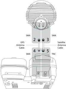
- Refer to the antennas installation guide for antenna mounting and location requirements.
- Connect the antenna cable labelled “GPS” to the SMA antenna connector labelled “GPS”.
- Connect the antenna cable labelled “Inmarsat” to the SMA antenna connector labelled “SAT”.
- Connect the GPS-SMA (Female) cable end to the IsatDock2 MARINE’s SMA connector.
- Connect the TNC (Female) antenna cable end to the IsatDock2 MARINE’s satellite connector.
![]() WARNINGDO NOT pull with force on the cables from the rear of the IsatDock2 MARINE. Please install strain relief clamping for the antenna cables where required. Correct installation of the antenna system is a vital part of the IsatDock MARINE system, to ensure reliable functionality, and drop-free calls.
WARNINGDO NOT pull with force on the cables from the rear of the IsatDock2 MARINE. Please install strain relief clamping for the antenna cables where required. Correct installation of the antenna system is a vital part of the IsatDock MARINE system, to ensure reliable functionality, and drop-free calls.
![]() WARNINGChanges or modifications not expressly approved by BEAM Communications could void the product warranty
WARNINGChanges or modifications not expressly approved by BEAM Communications could void the product warranty
![]() WARNINGTo satisfy FCC RF exposure requirements for mobile transmitting devices, a separation distance of 55 cm or more should be maintained between the antenna of this device and persons during device operation. To ensure compliance, operations at closer than this distance is not recommended.
WARNINGTo satisfy FCC RF exposure requirements for mobile transmitting devices, a separation distance of 55 cm or more should be maintained between the antenna of this device and persons during device operation. To ensure compliance, operations at closer than this distance is not recommended.
Privacy Handset and Mounting Cup
There are two unique mounting cups fit for the privacy handset. (1) springless cup for either a desk mounted cradle position or a wall mounted cradle position. (2) spring cup for heavy duty use.
(1) Springless CupDesk mounted cradle positionThe ‘springless’ cup is fitted to the docking station with the mounting clip in a ‘flush’ position.
Wall mounted cradle positionThe mounting clip can be slid out and reversed, producing a protruding point that the Privacy handset rests upon. For a wall mounted docking station this retains the privacy handset and the springless cup has enough height to allow the handset to rise up off the clip and out of the mounting cup. This option would be best suited for stable conditions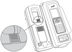
(2) Spring Cup – Heavy duty useIn harsh environments, the Privacy handset is actively retained in the mounting cup. This is achieved by using the ‘spring’ mounting cup. To remove the handset from the cup, the phone is lifted up against the pressure of the spring until it clears the lower mounting pip and can be removed from the docking station.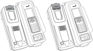
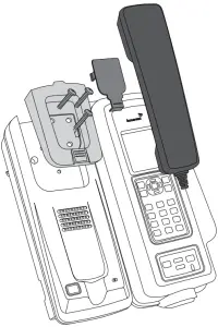
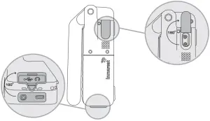
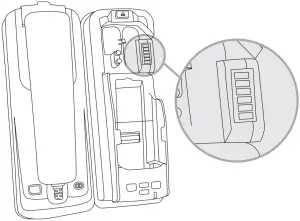
Docking and Un-docking your IsatPhone 2
- Lift the antenna ‘cover’ and rotate through 180 degrees, then push down into the open position.
- The ‘cover’ in the base of the phone should be rotated 180 degrees to be in the open position

- Detach the USB/Audio adapter from the dock and insert by hand in the base of the IsatPhone 2.
- To dock the handset, open the antenna slightly, align the IsatPhone 2 with the phone tray and slide the handset down until it seats flush to the bottom of the tray. Swing the phone down into the cradle by applying pressure to the top of the handset. An audible ‘click’ is heard when the phone is in the docked position.
- To remove the handset from the cradle, press the EJECT button at the top of the docking station. The dock will swing out and the handset can be removed.
- Place the adapter back in its dedicated slot, when the phone is not in the docking unit.
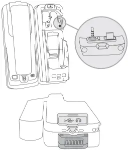
Mounting Orientation
There are four keyhole shaped slots in the mounting bracket that mate with feet on the rear of the docking station. To attach the bracket, the larger end of the keyhole will pass over the feet. The dock is then slid down to lock the feet into the narrow section of the keyhole.
![]() Fit the docks feet in large holes of the bracket
Fit the docks feet in large holes of the bracket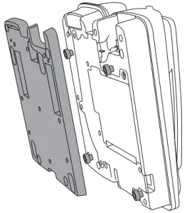
![]() Slide Dock down
Slide Dock down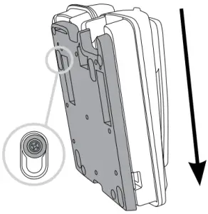
![]() Final lock position
Final lock position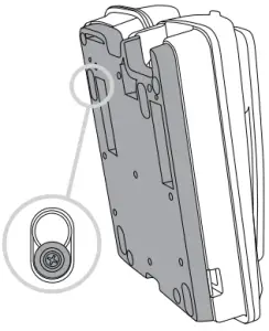
The IsatDock2 MARINE can be mounted either flat on a desk or vertically to a wall. When wall mounting the docking station, the wall bracket is first screwed to the wall and the dock is slid into place. One security pin is then slid into place locking the dock to the wall.The docking station can be elevated in the desk mounted orientation by two retractable feet included in the mounting bracket.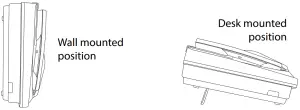
![]() NOTE: For extensive mounting instructions please refer to your IsatDock2 MARINE Manual.
NOTE: For extensive mounting instructions please refer to your IsatDock2 MARINE Manual.
IsatDock2 MARINE Front Panel
| Location | Button Mode | Action | LED/Sound |
 |
Mute Press ON/OFF | In a Call:Mute the microphone (uplink) on the privacy handset if connected to cradle. | LED turns RED – MutedLED turns OFF – Not mutedLED flashing Yellow – RJ11/POTS in use |
|
|
UP/DOWN | In a Call:Increase/decrease volume on the internal hardware or privacy handset (optional accessory) if connected to cradle. | Audio will sound louder/quieter in privacy handset with each press. |
| Out of Call:Increase/decrease volume of incoming ring tone on the internal hardware speaker. | A beep will sound indicating the increased/decreased ring tone volume | ||
 |
Single Press (1 second) | Send a Personal Alert message to the IsatPhone 2’s pre-configured destination * | A beep will sound to indicate that a Personal Alert button was pressed.# |
|
|
Brightness dual button simultaneous press (1 second) | Out of Call:Enter LED brightness change mode. Press UP and DOWN arrows to vary intensity.Mode will automatically exit after 5 seconds after the last button press. | All LED’s will change to WHITE and a double beep will sound when entering brightness change mode.A short single beep will sound when exiting change mode. |
 |
Speakerphone press ON/OFF | In a Call:Terminate call if speakerphone mode is active Activate speakerphone mode if Privacy Handset mode is active. | LED turns GREEN – Speakerphone mode activeLED turns OFF – Speakerphone mode not active |
| Out of Call:Answer inbound call in speakerphone mode |
 OR
OR
* This action is optional, only when the Personal Alert Mode for your IsatPhone 2 is configured.# A beep will only sound if audible alerts are enabled in the Falcon
BEAM Communications Pty Ltd 5/8 Anzed Court, Mulgrave Victoria, 3170, AUSTRALIAWeb: www.beamcommunications.comInformation: [email protected]Support: [email protected]Tel: +61 3 8588 4500Fax: +61 3 9560 9055
 report this ad
References
[xyz-ips snippet=”download-snippet”]