 ZW39Z-Wave Smart Plug(Dimmer)Installation Manual

INTRODUCTION
The EVA LOGIK ZW39 is a Z-Wave enabled 500W receptacle designed for most residential lighting and applications. It’s compatible with LED, halogen, incandescent.The ZW39 fully works with the Fibaro, Smartthings, Wink hub as well as all other certified Z-Wave controllers.
Specifications:
Power: 120VAC, 60HzLoading: 500WFrequency: 908.42MHzFCC ID: OXGZW36IC: 10460A-ZW36
Min / Max brightness level setting( Refer to Parameter 9/10 )
- Press the button 5 times quickly, the white indicator light flashes slowly, enter the setting “Min brightness” mode, and the load lamp automatically adjusts to the min brightness.
- Hold the button to adjust the brightness of the bulb, select the appropriate brightness to set the min brightness.
- Quick Press the button 5 times to confirm it (the min brightness setting is completed). It will be entered into the “Max Brightness” setting automatically, the bulb will adjust to the max brightness.
- Hold the button to adjust the brightness of the bulb, select the appropriate brightness to set the max brightness.
- Press the button 5 times to confirm.
- After confirmation, the brightness of the bulb will automatically be adjusted from the set min brightness to the max brightness, then from the max brightness to the min brightness, finally staying at the set min brightness. The white indicator light stops flashing.
- Min / Max brightness level settings are completed.Remark: If the setting is not confirmed at Step 3/Step 5, the setting mode will be exited after 10S, and the adjusted value will not be saved.
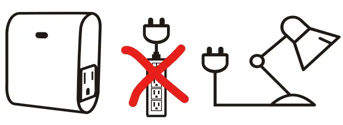
Plug the light you want to control into the Z-Wave Smart plug-controlled outlet.NOTE: Plug directly into an outlet, do not use with extension cords

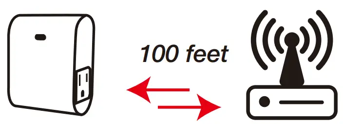
Note: Your device may need to be within 100 feet of the controller to be included. If so, include the device in the network within 10 feet of the controller and relocate it to the desired position in your home. Be sure to refresh the network if the device is included in this manner.

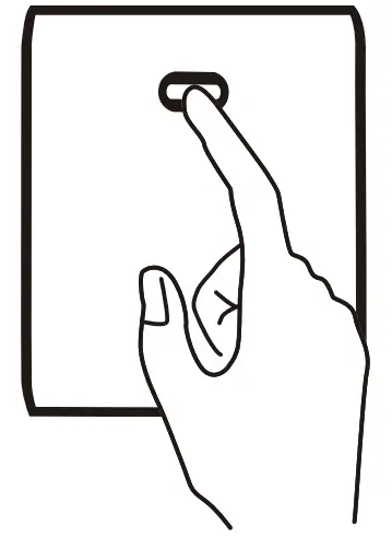
Add to Z-Wave NetworkPut the Z-wave interface controller into “Add” mode, triple press the Program button.It will be included in the network. (Once your controller is confirmed, refresh the Z-Wave network to optimize performance. )

Remove from Z-Wave Network Put the Z-Wave interface controller into “Remove” mode, triple press the Program button. It will be excluded from the network.
To return your switch to factory defaultsManual: Click the button 2 times quickly, and hold for at least 10 seconds.Host reset: Remove it from the host and the device is the factory reset.Note: This should only be used in the event your network’s primary controller is missing or otherwise inoperable
Association(LED flashes 2 times when the configuration parameter changes.)Support 2 groups, each group max support 2 devicesGroup 1 lifelineGroup 2 send a basic set
Parameter Settings
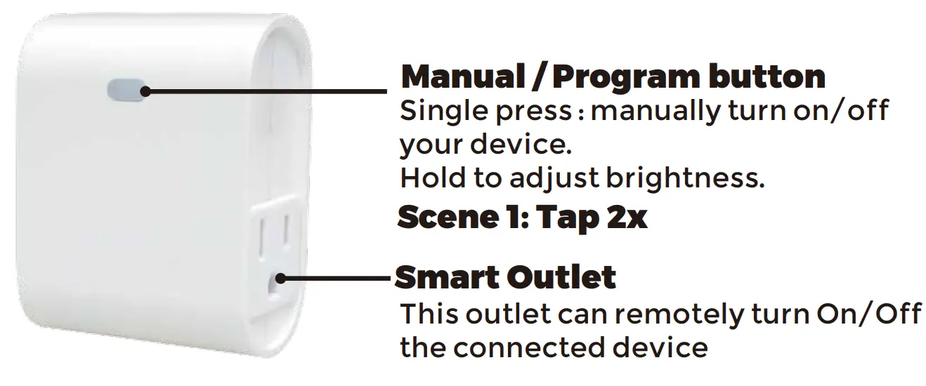
- ADD/REMOVE–Manual add mode: Press the button 3 times.–Auto-add mode: LED will blink within 30 seconds after first power on1 Tap: control on/offHold: control brightness
- Factory reset:Manual: Click the button 2 times quickly, and hold for at least 10 secondsHost reset: Remove it from the host and the device is the factory reset.
- LED indicator (quickly press 6x: change Parameter)(LED flashes 2 times when the configuration parameter changes.)Parameter=1, Size=1, Default =0Value=0 Load Off, Indicator LED OnValue=1 Load On, Indicator LED OffValue=2 Always OffValue=3 Always On
- Auto Turn-OFF Timer(LED flashes 2 times when the configuration parameter changes.)Parameter =2, Size=4, Values: 0 – 65535 (Min); Defualt V=0 turn off outlet
- Auto Turn-ON Timer(LED flashes 2 times when the configuration parameter changes.)Parameter =4, Size=4, Values: 0 – 65535 (Min); Default V=0 turn on outlet
- Restores state after a power failure(quickly press 10x: change Parameter)(LED flashes 2 times when the configuration parameter changes.)Parameter=6, Size=1,Value=0 Output offValue=1 Output onValue = 2 Restores state after power failure
- Dimming speed — How fast or slow the light turns on/off when you hold the switch. (LED flashes 2 times when the configuration parameter changes.)Parameter=7, S=1, V=XX(0x01—0x63) Defualt V=1
- The multilevel minimum value can be set (ALL )(quickly press 5x) (LED flashes 2 times when the configuration parameter changes.)Parameter=8, Size=1, Value=0 DisableValue=1. .Value=99Default = 10
- Multilevel maximum value can be set (ALL )(quickly press 5x) (LED flashes 2 times when the configuration parameter changes.)Parameter=9, Size=1, Value=0 DisableValue=1. .Value=99Default = 99
- Local on or off dimmer speed control by parameter 9(LED flashes 2 times when the configuration parameter changes.)Parameter=10, Size=1, Value=0 Control by parameter 9Value=1 On/off instantlyDefault = 0
- Dimmer speed — How fast or slow the light turns dim when adjusting the switch. (LED flashes 2 times when the configuration parameter changes.)Parameter=11, Size=1, Value=1 from 0x63 to 0x00 or from 0x00 to 0x63 need 1sValue=2 from 0x63 to 0x00 or from 0x00 to 0x63 need 2s..Value=10 from 0x63 to 0x00 or from 0x00 to 0x63 need 99sDefault = 412: Scene functionscene 1: Tap 2x
FCC / IC
This device complies with part 15 of the FCC and Industry Canada license-exempt RSS standard(s). Operation is subjected to the following two conditions:(1) this device may not cause harmful interference, and (2) this device must accept any interference received, including interference that may cause undesired operation.
FCC NOTE:The manufacturer is not responsible for any radio or TV interference caused by unauthorized modifications to this equipment.Such modifications could void the user’s authority to operate the equipment.
- Reorient or relocate the receiving antenna.
- Increase the separation between the equipment and receiver.
- Connect the equipment into an outlet on a circuit different from that to which the receiver is connected.
- Consult the dealer or an experienced radio/TV technician for help
NOTE:This equipment has been tested and found to comply with the limits for a Class B digital device, pursuant to Part 15 of the FCC Rules.These limits are designed to provide reasonable protection against harmful interference in a residential installation. This equipment generates, uses, and can radiate radio frequency energy and, if not installed and used in accordance with the instructions may cause harmful interference to radio communications. However, there is no guarantee that interference will not occur in a particular installation. If this equipment does cause harmful interference to radio or television reception, which can be determined by turning the equipment off and on, the user is encouraged to try to correct the interference by one or more of the following measures:Important note:To comply with the FCC RF exposure compliance requirements, no change to the antenna or the device is permitted.Any change to the antenna or the device could result in the device exceeding the RF exposure requirements and void the user’s authority to operate the device.
COMMANDCLASS
GENERIC DEVICE CLASS:11 – GENERIC_TYPE_SWITCH_MULTILEVELSPECIFIC DEVICE CLASS:01 – SPECIFIC_TYPE_POWER_SWITCH_MULTILEVEL
COMMANDCLASS:5E – COMMAND_CLASS_ZWAVEPLUS_INFO26 – COMMAND_CLASS_SWITCH_MULTILEVEL27 – COMMAND_CLASS_SWITCH_ALL70 – COMMAND_CLASS_CONFIGURATION85 – COMMAND_CLASS_ASSOCIATION8E – COMMAND_CLASS_MULTI_CHANNEL_ASSOCIATION59 – COMMAND_CLASS_ASSOCIATION_GRP_INFO55 – COMMAND_CLASS_TRANSPORT_SERVICE86 – COMMAND_CLASS_VERSION72 – COMMAND_CLASS_MANUFACTURER_SPECIFIC5A – COMMAND_CLASS_DEVICE_RESET_LOCALLY73 – COMMAND_CLASS_POWERLEVEL9F – COMMAND_CLASS_SECURITY_26C – COMMAND_CLASS_SUPERVISION7A – COMMAND_CLASS_FIRMWARE_UPDATE_MD
 |
CAUTION – PLEASE READ! |            |
| This device (ZW39) is intended for installation in accordance with the National Electric Code and local regulations in the United States, or the Canadian Electrical Code and local regulations in Canada. If you are unsure or uncomfortable about performing this installation consult a qualified electrician. |
           |
WARNING – SHOCK HAZARD |            |
| TURN OFF THE POWER to the circuit for the switch and lighting fixture at the service panel (circuit breaker) prior to installation. ALL WIRING CONNECTIONS MUST BE MADE WITH THE POWER OFF to avoid personal injury and/or damage to the switch. |
           |
OTHER WARNINGS |            |
| Risk of FireRisk of Electrical ShockRisk of Burns |
           |
MEDICAL EQUIPMENT |            |
| Please DO NOT use this switch to control Medical or Life Support equipment. Z-Wave devices should never be used to control the On/Off status of Medical and/or Life Support equipment. |
           |
CONTROLLING APPLIANCES |            |
| Please exercise EXTREME CAUTION when using Z-Wave devices to control appliances. The reason being is because the appliance you want to control may be in a separate room and if unintentional behavior occurs (such as a device turning on or off – either intentionally via schedules, or unintentionally via network error) this event may lead to a hazardous condition. For these reasons, please note the following suggestions:1) Do not include Z-Wave devices in Groups or Scenes if they control appliances.2) Do not use Z-Wave devices to control electric heaters or any other appliances which may present a hazardous condition due to unattended, unintentional, or automatic power control |
References
[xyz-ips snippet=”download-snippet”]


