EXTECH CLT600 Cable Locator and
 Tracer User Guide
Application Illustrations
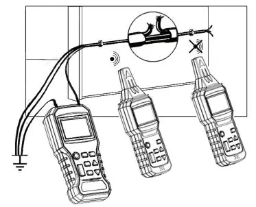
Figure 1 Locating wire breaks. Diagram shows one Transmitter in a fixed location and one Receiver being used in two locations. The Receiver position on the left is detecting a signal, while the Receiver position on the right is not detecting a signal.
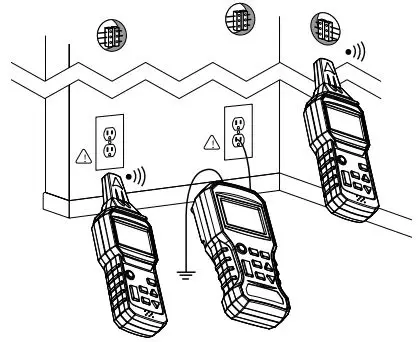
Figure 2 Locating and tracing lines and receptacles
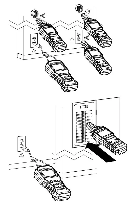
Figure 3 Two examples of matching connected points in a circuit.
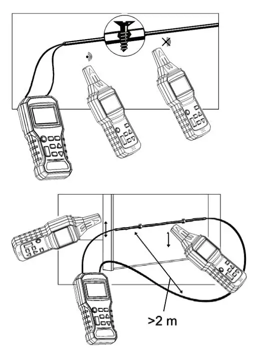
Figure 4 Two examples of broken line detection tests. Top diagram shows a two-conductor test; bottom diagram shows a single-conductor test. Diagrams show one Transmitter in a fixed location and one Receiver being used in two locations. On the top diagram, the Receiver position on the left is detecting a signal, while the Receiver position on the right is not.
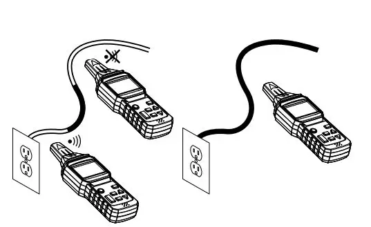
Figure 5 Non-Contact Voltage Detection
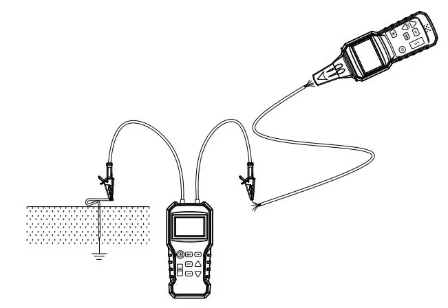
Figure 6 Using the supplied earth ground spike (rod)
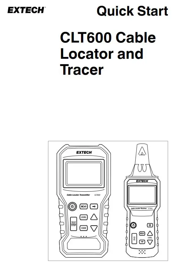
Quick Start
Note: Please refer to the User Manual for complete instructions: https://support.flir.com.
SAFETY
- This device has been designed and tested according to CE Safety Requirements for Electronic Measuring Apparatus, EN 61010-1 EN 61326-1 and other safety standards.
- Safety Rating: Category III 450 V.
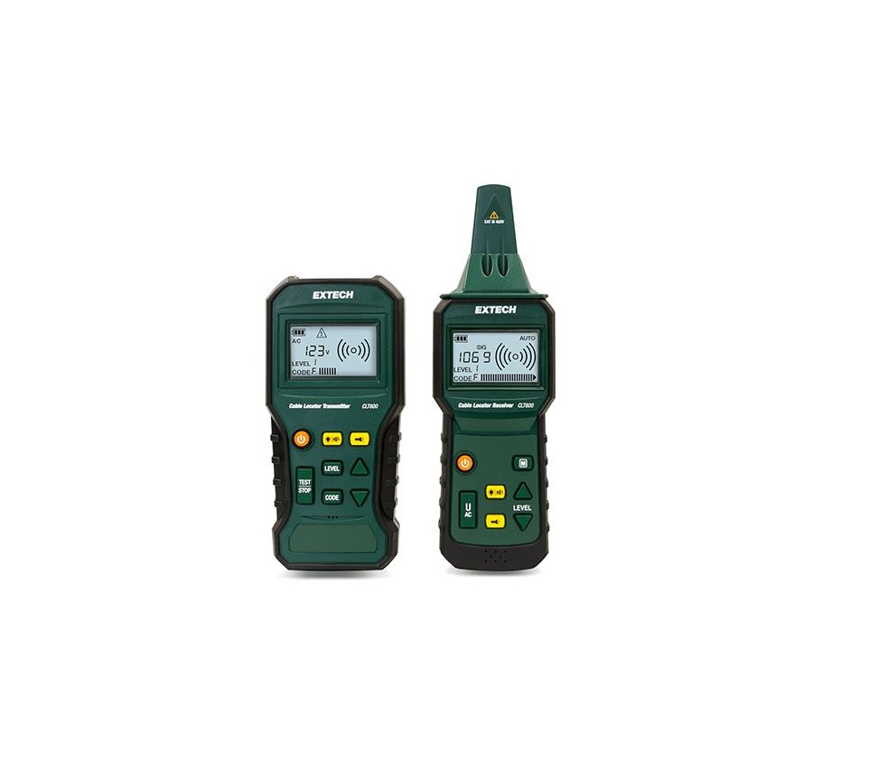
TRANSMITTER AND RECEIVER DESCRIPTIONS
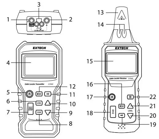
Transmitter Description (shown on left, above)
- Negative (COM) ground, or common terminal. Connect the black test lead here.
- Positive `+’ terminal. Connect the red test lead here.
- Work lights
- LCD Screen
- Power button (short press ON/OFF).
- LEVEL button. Press and `LEVEL’ will flash on the display. Select one of three signal levels using the arrow buttons.
- TEST/STOP button. Press to send/stop the transmission signal.
- CODE button. Long press and `CODE’ will flash on the display. Select a code (F, E, H, d, L, C, O, A) using the arrow buttons.
- Down arrow. Short press to decrement the selection in the LEVEL or CODE modes.
- Up arrow. Short press to increment the selection in the LEVEL or CODE modes.
- Work light button (short press).
- Backlight (short press) and beeper mute (long press) button.Receiver Description (shown on right, above)
- Receiver antenna. Detects a transmitted signal or a voltage source in non-contact detector mode.
- Work lights
- LCD screen
- Backlight (short press) and beeper mute (long press) button
- Power button (short press).
- UAC button. Short press to access the non-contact voltage detector. Press again to return to normal Receiver mode.
- Work light button (short press).
- Down arrow. When in Manual Mode, short press to decrease the sensitivity level.
- Up arrow. When in Manual Mode, short press to increase the sensitivity level.
- Manual (M) button. Short press to access the Manual signal detection mode. Select from eight sensitivity levels, using the LEVEL buttons.
NOTE: The battery compartment is located on the back of the instruments. Each instrument requires 6 x 1.5 V `AAA’ batteries.
DISPLAY DESCRIPTION
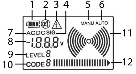
- Battery status.
- Beeper ON/OFF status.
- Voltage warning.
- Signal indicator (indicates that the digital display is showing the received signal strength).
- Manual detection mode.
- Automatic detection mode.
- Voltage AC or DC (digital display is showing an AC or DC volt-age measurement).
- Digital display for voltage measurement (Transmitter) or the Transmitter’s output Level as selected by the Transmitter operator.(Receiver).
- Transmission strength (Level) selection.
- Code ID indicator.
- Signal indicator. Radiating arc graphics appear when Transmitter is sending a signal. On the Receiver, the number of arcs corresponds to the Receiver’s ‘sensitivity level’.
- Bar-graph shows signal level.
TRANSMITTER OPERATING MODES
Transmitter TEST and TRANSMIT ModeIn TEST mode (default), you can measure AC or DC voltage from 12 V to 450 V AC / DC with the test leads. You also transmit a signal: Press the TEST/STOP button to allow the Transmitter to send a signal. Press the TEST/STOP button again to switch the signal OFF.
Transmitter LEVEL Select ModePress the LEVEL button, the `LEVEL’ text will flash. Use the arrows to select the strength of the transmission signal (level: 1~3). Press LEVEL again to return to the TEST Mode.CODE Selection ModeCodes are used to differentiate two or more Transmitters that can be used to detect a break in a circuit. Long press the CODE button, the `CODE’ text will flash. Use the arrows to select the code for the transmission signal (F, E, H, d, L, C, O, A). Press CODE again to return to the TEST Mode.
RECEIVER OPERATING MODES
Automatic Detection ModeIn Auto Detection mode (default) you can detect the high frequency transmission signal at the highest sensitivity. The Receiver responds to the detected signal with a variable tone (550 Hz ~ 1.6 kHz) and a bar-graph indication. The stronger the signal, the higher the frequency of the tone and the more bars on the graph.
The Receiver displays SIG (Signal) and the numeric value of the received signal strength. The optional transmission Code, sent from the Transmitter, is also displayed.
Manual Detection ModePress the M button and select the signal sensitivity level manually (8 steps) using the arrows. Press M again to return to the Auto-Detection mode.
Non-Contact Voltage Detection Mode (UAC)Press the UAC button. In this mode you can detect AC voltage without having to make contact with the circuitry. See the dedicated section later in this document.
SINGLE-POLE APPLICATIONS
Locating Opened Wires
- Refer to Figure 1 in the Application Illustrations section.
- Connect from the red, positive (+) terminal to a single conductor.
- Connect from the black (COM) terminal to earth ground.
- If there are additional conductors in the same conduit or cable, they will also have to be connected to earth ground. For convenience, use the supplied ground rod if testing outdoors.
- The Receiver can now detect the location of the wiring fault.
Locating and Tracing Lines and ReceptaclesWARNING: Do not perform this test on a live circuit.
- Connect from the red, positive (+) terminal to the `hot’ conductor.
- Connect from the black (COM) terminal to earth ground. For convenience, use the supplied ground rod if testing outdoors.
- Refer to Figure 2 in the Application Illustrations section for examples.
TWO-POLE APPLICATIONS
Locating and Matching Connected Points in a Circuit (120 V)
- Connect the supplied AC Socket Adaptor to the Transmitter and plug the AC connector into an AC receptacle.
- The Transmitter can now measure the voltage of the mains and transmit the signal through the mains.
- The Receiver can then trace the mains and determine if a receptacle is connected on the same line, if another receptacle or breaker is connected on the same circuit.
- Refer to Figure 3 in the Application Illustrations section for examples.
Broken Line Detection
- Method 1: Connect both terminals of the Transmitter, one to each wire, at one end of the line. At the other end of the line, connect the wires together.
- Method 2: Connect both terminals of the Transmitter to each end of a single wire in the line.
- The Receiver can now determine the position of the broken wire in the signal line in the wall or floor.
- Refer to Figure 4 in the Application Illustrations section for examples.
NON-CONTACT AC VOLTAGE DETECTION
- The circuit under test must be live and connected to the mains.
- Set the Receiver to the UAC mode.
- Hold the tip of the Receiver close to the source of AC voltage.
- The mains AC voltage detected by the Receiver in the UAC mode only indicates whether or not the circuit is live.
- While searching for the ends of the supply lines, the lines must be connected separately, one by one.
- The number of bars on the bar graph and the audible tone’s pitch increases as the strength of the detected signal increases. The closer the sensor is to the source of voltage, the stronger the signal detection.
- Refer to Figure 5 in the Application Illustrations section for examples.
EARTH GROUND ROD (SPIKE) USE
- In applications that require an outdoor earth ground connection, use the supplied ground rod (spike) for convenience.
- Refer to Figure 6 in the Application Illustrations section.
- Carefully drive the supplied rod into the ground at the test area.
- Connect the test leads and set up tests as shown in the application instructions provided in the accompanying sections.
ADDITIONAL APPLICATIONS
Download the User Manual (https://suppport.flir.com) to learn about additional applications including Tracing Underground Circuits and Detecting Faults in Floor Heating Systems.
TWO-YEAR LIMITED WARRANTYFLIR Systems, Inc. warrants this EdTech brand instrument to be free of defects in parts and workmanship for two years from date of shipment (a six-month limited warranty applies to sensors and cables). To view the full warranty text please visit: http://www.extech.com/support/warranties.
CUSTOMER SUPPORTCustomer Support Telephone List: https://support.flir.com/contact Calibration, Repair, and Returns: [email protected]Technical Support: https://support.flir.comExtech website: www.extech.com
EXTECHQuick Start
Websitehttp://www.flir.com
Customer supporthttp://support.flir.com
Copyright© 2020, FLIR Systems, Inc. All rights reserved worldwide.
DisclaimerSpecifications subject to change without further notice. Models and accessories subject to regional market considerations. License procedures may apply. Products described herein may be subject to US Export Regulations. Please refer to [email protected] with any questions.
 report this ad
Publ. No.: NAS100049Release: AACommit: 70188Head: 70188Language: en-USModified: 2020-09-09Formatted: 2020-09-09
References
[xyz-ips snippet=”download-snippet”]