Extech Current Calibrator PRC10 User Manual
Additional User Manual Translations available at www.extech.com
Introduction
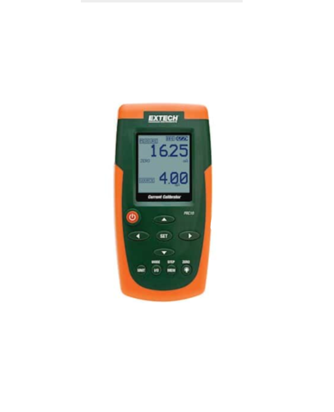
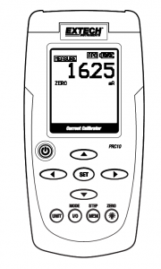
Thank you for selecting the Extech Model PRC10. This device is shipped fully tested and calibrated and, with proper use, will provide years of reliable service. Please visit the Extech Instruments website (www.extech.com) to check for the latest version of this User Guide. Extech Instruments is an ISO-9001 certified company.
Safety
International Safety Symbols This symbol, adjacent to another symbol or terminal, indicates the user must refer to the manual for further information
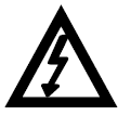 This symbol, adjacent to a terminal, indicates that, under normal use, hazardous voltages may be present
 Double insulation
Safety Notes
- Do not exceed the maximum allowable input range.
- Turn the unit OFF when the device is not in use.
- Remove the batteries if the device is to be stored for longer than 60 days.
- Never dispose of batteries in a fire. Batteries may explode or leak.
- Never mix battery types. Always install new batteries of the same type.
Cautions
- Improper use of this meter can cause damage, shock, injury or death. Read and understand this user manual before operating the meter.
- Always remove the test leads before replacing the battery.
- Inspect the condition of the test leads and the meter itself for any damage before operating the meter. Repair or replace any damage before use.
- If the equipment is used in a manner not specified by the manufacturer, the protection provided by the equipment may be impaired.
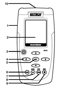
Meter Description
- AC adaptor input jack
- Display
- Power ON/OFF
- Source output adjustment arrow buttons
- Set button
- Unit button (mA or %)
- I/O MODE button
- MEM (memory STEP button)
- Backlight/ZERO button
- Test lead inputs
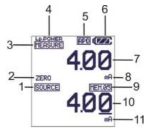
Display Layout
- SOURCE mode icon
- ZERO function status icon
- MEASURE mode icon
- Loop Power icon
- Auto Power OFF active icon
- Battery status icon
- Measure mode value
- Measure mode units icon
- Datalogger memory location
- Source mode value
- Source mode units icon
Keypad Descriptions and Operation
POWER BUTTON and AUTO POWER OFF FEATURE
- Use the POWER button to turn the unit ON or OFF. When the unit is powered up, a short self-test will ensue after which the display will stabilize.
- When the battery symbol flashes on the display, replace the battery as soon as possible. Low battery power may cause inaccurate readings and erratic meter operation.
- This instrument is equipped with Auto Power OFF which turns the meter off after 10 minutes of inactivity. To override this feature; press and hold the POWER button until the displayicon “APO” turns off.
UNIT BUTTONPress the UNIT button to select mA or % units.
I/O BUTTONMomentarily press the I/O button to select either SOURCE (output) or MEASURE (input).
MODE BUTTON (Loop Power)In the MEASURE mode, Press and Hold the MODE (I/O) button for 1 second to turn loop power on or off.
 (Backlight) BUTTONMomentarily press the Backlight button to turn the backlight on or off.
ZERO ( ![]() ) BUTTONIn the MEASURE or SOURCE mode, Press and Hold the ZERO (
) BUTTONIn the MEASURE or SOURCE mode, Press and Hold the ZERO ( ![]() ) button for 1 second to zero the meter.
) button for 1 second to zero the meter.
The arrow buttons are used to set the output value in the SOURCE mode.
- Select the SOURCE mode
- Press the ► or ◄ button select a digit for adjustment. The blinking underline curser identifies the digit selected.
- Press the ▼or ▲button to adjust the value of the digit. Press and Hold the ▼or ▲ button to rapidly adjust the value.
The SET button is used to manually step through the 5 stored output values.
- Select the SOURCE mode
- Press the SET button and the value stored in memory location 01 will be sourced. “MEM.01” appears in the display.
- Each press of the SET button will step through the 5 memory locations.
- The arrow buttons can be used to adjust the value in each memory location.
The STEP/MEM button is used to automatically step through the 5 stored output values. The meter can be set for a single cycle of the stored values or a continuous cycle.
- Select the SOURCE mode
- Press and HOLD the STEP/MEM button. ”STEPS” (single cycle) and “STEPC” (continuous cycle) will alternately appear in the display. Release the button when the desired mode isdisplayed.
- In single cycle mode the meter will source the current displayed in MEM01 for 5 seconds. The meter will then advance to MEM02 for 5 seconds. This will continue through MEM05and then step down through the memory locations. The cycle will end when MEM01 has been reached.
- In the continuous mode the cycle will continue until manually stopped.
- Momentarily press the STEP/MEM button to stop the cycle. “END” will briefly appear in the display.
STORING VALUES INTO MEMORY
The default values stored in the memory locations are:
Memory Location |
mA |
% |
|
M1 |
4.00mA |
0.0% |
|
M2 |
8.00mA |
25% |
|
M3 |
12.00mA |
50% |
|
M4 |
16.00mA |
75% |
|
M5 |
20.00mA |
100% |
To change the values in memory:
- Select the SOURCE mode
- Press the SET button to select the memory location to be changed.
- Press the arrow buttons to adjust to the new value
- Momentarily press the MEM button to store the value. The memory location icon will blink while the value is being stored.
Modes of Operation
MEASURE (Input) Mode of Operation In this mode, the unit will measure up to 50mADC.
- Turn the meter ON.
- “MEASURE” will appear in the display.
- Press the UNIT button to select mA or %
- Press and HOLD the “MODE-I/O” button for 1 second if 24V loop power is required. “Lp.POWER” will appear in the display.
- Connect the Calibration Cable to the meter.
- Connect the Calibration Cable to the device or circuit under test.
- Read the measurement on the LCD display.
SOURCE (Output) Mode of OperationIn this mode, the unit can source current up to 24mADC at 1000 ohms. The current can be output either manually or stepped from memory as described earlier.
- Turn the meter ON
- Press the “I/O” button to select SOURCE.
- Use the UNIT button to select % or mA.
- Connect the Calibration Cable to the meter
- Connect the Calibration Cable to the device or circuit under test
- Use the arrow buttons to set the desired output value in the lower display. The upper display indicates the actual current value being sourced. If the upper display does not matchthe set value, either the batteries need to be replaced or the load impedance is beyond the specified range.
Tilt Stand / Hanger
The rear stand is provides two methods for convenience in viewing.
- Pull the bottom portion of the stand out to place the unit on a flat surface for viewing.
- Pull the bottom and top portions of the stand out, and then rotate the stand to allow the unit to be hung.
Battery Replacement
When the battery icon appears on the display, the six AA batteries must be replaced.The battery compartment is located on the rear of the meter.
- Open the tilt stand, loosen the captive Philips head screw and remove the battery cover.
- Remove and replace the batteries, observing polarity.
- Replace and secure the battery cover.
 All EU users are legally bound by the Battery Ordinance to return all used batteries tocommunity collection points or wherever batteries / accumulators are sold.Disposal in household trash or refuse is prohibited. Disposal: Follow the valid legal stipulations in respect of the disposal of the device at the end of its lifecycle
Battery Safety Reminders
- Please dispose of batteries responsibly; always observe local, state, and federal regulations with regard to battery disposal.
- Never dispose of batteries in a fire. Batteries may explode or leak.
- Never mix battery types or old and new batteries. Always install new batteries of the same type.
Specifications
General SpecificationsDisplay Dot matrix LCDMaximum Load 1000 ohms @ 24mAMeter Power 6 AA batteries or AC adaptorAuto Power OFF Meter automatically powers off after 10 minutes of inactivityCurrent output capability 24mADC at 1000 ohmsOperating Temperature 41ºF to 104ºF (5ºC to 40ºC)Storage Temperature – 4oF to 140oF (-20oC to 60oC)Operating Humidity Max 80% up to 87ºF (31ºC) decreasing linearly to 50% at 104ºF (40ºC)Storage Humidity <80%Operating Altitude 7000ft (2000meters) maximumDimensions 159 x 80 x 44 mm (6.3 x 3.2 x 1.7″)Weight 232g (8.2 oz.) without batteries
Range Specifications
Mode |
Function |
Range (Resolution) |
Accuracy(% of reading) |
| Measure | Current | 0 to 50mA (0.01mA) | ± (0.01% + 1 digit) |
| Percent (%) | -25% to +230% (0.1%) | ||
| Source | Current | 0 to 24mA (0.01mA) | |
| Percent (%) | -25% to +125% (0.1%) | ||
| Power | Loop Power | 24 to 30VDC, <50mA |
Two-year Warranty
FLIR Systems, Inc. warrants this Extech brand instrument to be free of defects in parts and workmanship for two years from date of shipment (a six-month limited warranty applies to sensors and cables). To view the full warranty text please visit: http://www.extech.com/support/warranties.
Calibration and Repair Services
FLIR Systems, Inc. offers calibration and repair services for the Extech brand products we sell. We offer NIST traceable calibration for most of our products. Contact us for information on calibration and repair availability, refer to the contact information below. Annual calibrations should be performed to verify meter performance and accuracy. Product specifications are subject to change without notice. Please visit our website for the most up-to-date product information: www.extech.com.
Contact Customer Support
Customer Support Telephone List: https://support.flir.com/contact Calibration, Repair, and Returns: Technical Support: https://support.flir.com
Read More About This Manual & Download PDF:
References
[xyz-ips snippet=”download-snippet”]