![]()
EXTECH Current / Voltage Calibrator 412355A User Manual

Model 412355A
Additional User Manual Translations available at www.extech.com
Introduction
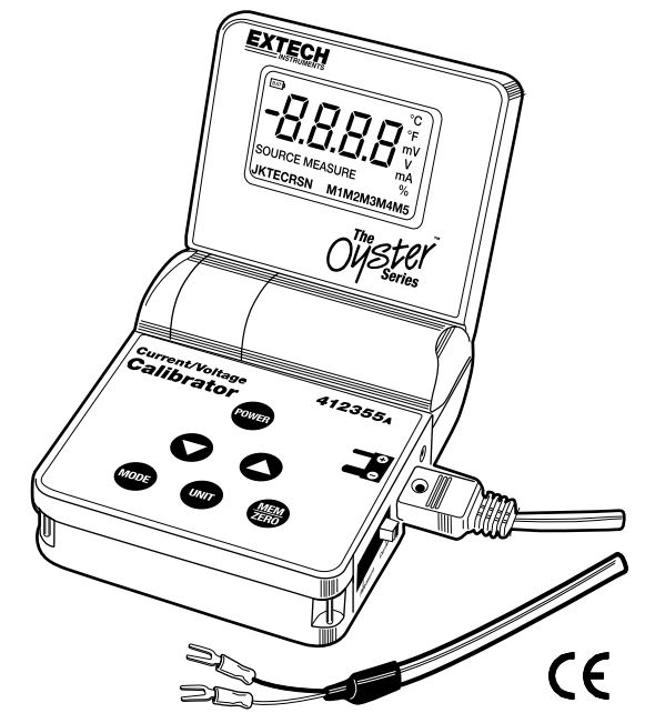
Congratulations on your purchase of the Extech Current/Voltage Calibrator. The Model 412355A can measure and source current and voltage. The Oyster Series meters have a convenient flip up display with neck-strap for hands-free operation. This meter is shipped fully tested and calibrated and, with proper use, will provide years of reliable service.
Meter Description
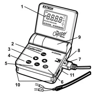
- LCD display
- POWER button
- UP and DOWN buttons
- MODE button
- UNIT button
- MEM and ZERO button
- Input/Output mini-connector
- AC adaptor jack
- Battery compartment
- Neck strap holders
- Function switch
Battery Replacement
When the LOW BAT message appears on the LCD, replace the 9V battery as soon as possible.
- Open the calibrator’s lid as far as possible.
- Open the battery compartment using a coin at the arrow indicator.
- Replace the battery and close the cover.
Operation
POWER BUTTON and AUTO POWER OFF FEATURE
- Use the POWER button to turn the unit ON or OFF. When the unit is powered up, a short selftest will ensue after which the display will stabilize.
- This meter can either be powered by one 9V battery or an AC adapter.
- When the battery symbol appears on the LCD display, replace the battery as soon as possible. Low battery power may cause inaccurate readings and erratic meter operation.
- This instrument is equipped with Auto Power OFF which turns the meter off after 10 minutes of inactivity. To override this feature; press and hold the MODE button until the display shows
 (auto power off de-activated) or (auto power off activated
FUNCTION SLIDE SWITCHSlide the Function switch on the side of the meter to the desired function (Voltage or Current)
MODEPress the MODE button to select either SOURCE (output) or MEASURE (input)
UNIT BUTTONPress the UNIT button to select:
- Voltage mode: mV or V in source.
- Current mode: mA or % in source or measure
▲▼ OUTPUT ADJUST BUTTONSPress the ▲ ▼buttons to increase or decrease the output voltage or current value in the sourcemode.
- Press the ▲ button once to increase the value in one digit steps.
- Press and hold the ▲ button to increase the value in 10 digit steps.
- Press and hold the ▲ button > 2 sec and then press the ▼ to increase the value in 100digit steps
- To decrease the value, use the ▼ button as described above.
ZERO BUTTONThe ZERO button manually zeros the display in the MEASURE mode.
- Set the meter to the MEASURE mode
- Short the input jack
- Press and release the ZERO button.
MEM BUTTONThe memory feature provides 5 user settable source values for stepped calibration outputs. Thefeature is available for Voltage, mA and % in the SOURCE mode. The memory values are stored in nonvolatile memory and are not erased when power is turned off.
Sourcing from the stored memory values:
- Select the Source mode
- Press the MEM button. The M1 icon (memory location 1) will appear in the display and thevalue stored in that location will be displayed and sourced.
- Repeated pressing of the MEM button will step through the 5 memory locations.
NOTE: The “SOURCE” icon will blink when the output value has not reached a stable level.The common cause for the “SOURCE” icon to remain blinking is that the load impedance istoo high in the current mode or too low in the voltage mode.
Storing values into memory:
- Select and display a memory location (M1 to M5)
- Press the ▲ ▼buttons to adjust the display to the desired source value.
- Press and hold the MEM button for > 2 seconds. The displayed value will be stored into the displayed memory location.
Default memory values.Five common source values are permanently programmed in memory as the default values.These values can be replaced by user selected values.To reset the meter to the default memory values:
- Turn the meter on and select the SOURCE mode.
- Press and hold the POWER button for >4 seconds. will briefly appear in the display and the default values will be stored into memory.

Over-range / Under-range IndicationSignals above or below the units ranges will be indicated by “HHHH” for above and “LLLL” forbelow.
Measure and Source
MEASURE (Input)In this mode, the unit will measure voltage or current.
- Select Voltage or Current on the Function switch.
- Turn the meter ON
- Press the MODE button to select MEASURE
- Press the UNIT button to select mA or % if current is selected.
- Connect the Calibration Cable to the meter.
- Connect the Calibration Cable to the device or circuit under test.
- Read the measurement on the LCD display.
SOURCE (Output)In this mode, the unit will source (output) voltage or current.
- Select Voltage or Current on the Function switch.
- Turn the meter ON
- Press the MODE button to select SOURCE
- Press the UNIT button to select V or mV if voltage is selected or to select mA or % if current is selected.
- Connect the Calibration Cable to the meter.
- Connect the Calibration Cable to the device or circuit under test.
- Use the ▲ ▼buttons to select the desired output value. Use the LCD display to verify the output level. Alternatively, use the stored calibration values in memory as described in the MEM button section.
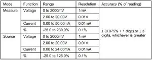
- For the -25% to 125% output range the output is 0 to 24mA.

NOTE: The “SOURCE” icon will blink when the output value has not reached a stable level. The common cause for the “SOURCE” icon to remain blinking is that the load impedance is too high in the current mode or too low in the voltage mode.
Specifications
General Specifications
- Display: 9999 count LCD
- Meter Power: 9 volt battery or 9V AC adaptor
- Auto Power OFF: Meter automatically powers off after 10 minutes of inactivity
- Current output capability: 24mA at 1000 ohms
- Operating Temperature: 41ºF to 104ºF (5ºC to 40ºC)
- Storage Temperature: -4oF to 140oF (-20oC to 60oC)
- Operating Humidity: Max 80% up to 31ºC (87ºF) decreasing linearly to 50% at 40ºC (104ºF)
- Storage Humidity: <80%
- Operating Altitude: 7000’ (2000m) maximum
- Dimensions: 3.8 x 4.7 x 1.8” (96 x 118 x 45mm) folded
- Weight: 12 oz. (340g)
- Accessories Supplied: 9V battery, AC adaptor and calibration cable with spade lugs
Range Specifications
Two-year Warranty
FLIR Systems, Inc. warrants this Extech brand instrument to be free of defects in parts and workmanship for two years from date of shipment (a six-month limited warranty applies to sensors and cables). To view the full warranty text please visit: http://www.extech.com/support/warranties.
Calibration and Repair Services
FLIR Systems, Inc. offers calibration and repair services for the Extech brand products we sell. We offer NIST traceable calibration for most of our products. Contact us for information on calibration and repair availability, refer to the contact information below. Annual calibrations should be performed to verify meter performance and accuracy. Product specifications are subject to change without notice. Please visit our website for the most up-to-date product information: www.extech.com
Contact Customer Support
Customer Support Telephone List: https://support.flir.com/contactCalibration, Repair, and Returns: [email protected]Technical Support: https://support.flir.com
Copyright © 2013-2021 FLIR Systems, Inc.All rights reserved including the right of reproduction in whole or in part in any formwww.extech.com
References
[xyz-ips snippet=”download-snippet”]