![]()
User ManualHigh Voltage DetectorMODEL DV690
Introduction
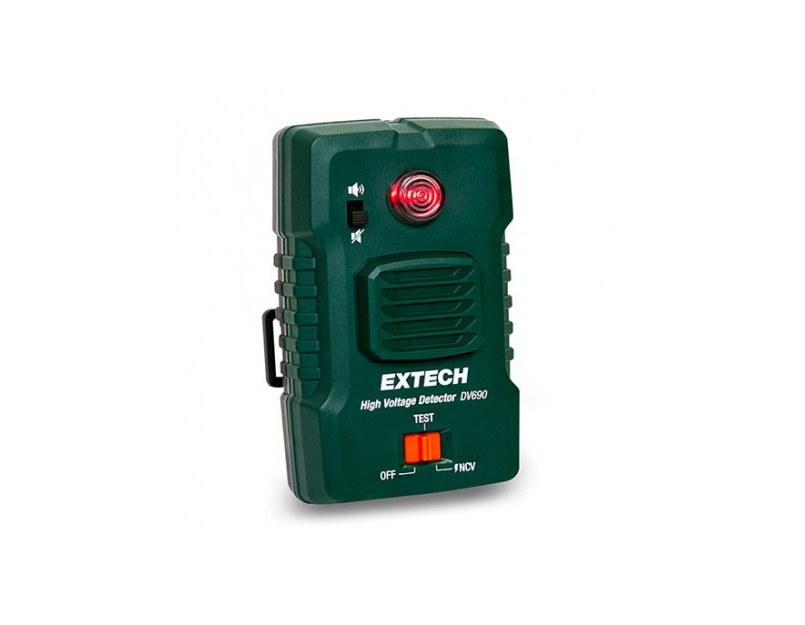
- Product OverviewThe Extech High Voltage Detector, Model DV690, senses the presence of AC voltage and alerts you (audibly and visibly) when you are in close proximity to live equipment and dangerous voltages. The non-contact sensor plate detects radiated electrical fields as it nears a live conductor.
- Product Features• Detects electrical fields from 100 V AC to 69 kV AC• Frequency bandwidth: 50 to 60 Hz• Bright LED alert indicator• Loud buzzer alarm (106 dB) with mute switch• Built-in safety self-test function• Can be held in hand or worn around the neck (supplied breakaway lan-yard), clipped to a front pocket or belt, or strapped on an arm (supplied elastic strap)• Universal `hot stick’ option using the supplied adaptor• Detector can be placed in the supplied soft protective pouch during use• Durable product housing with rugged, textured hand grip• Battery operated• Supplied with a hard-shell carrying case, breakaway lanyard, arm strap, soft pouch, hot stick adaptor, clip for belt or pocket mounting, 3 x `AA’ batteries and instructions• Complies with EN 613261 safety standard
Product Description
- Front and Back Descriptions
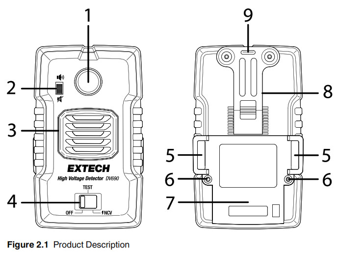
 1. LED alert indicator: Lights when voltage is detected2. Buzzer mute switch3. Audible buzzer: Sounds when voltage is detected4. Function select switch5. Slots for elastic arm strap or hot stick adaptor6. Battery compartment screws7. Battery compartment cover8. Belt/pocket clip9. Neck-strap lanyard attachment slot
 - Hot Stick’ Attachment AdaptorFigure 2 Hot Stick Adaptor Accessories1. Cylinder2. Cylinder screw3. Cylinder bracket4. Universal spline connectorFor instructions on assembling the adaptor, connecting it to the detector, and attaching a hot stick, see Section 6, Using a Hot Stick.
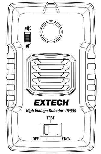
- Control Switches1. Buzzer enabled2. Buzzer muted3. Power OFF position4. Self-Test position5. NCV (non-contact voltage) detection mode
 1. LED alert indicator: Lights when voltage is detected2. Buzzer mute switch3. Audible buzzer: Sounds when voltage is detected4. Function select switch5. Slots for elastic arm strap or hot stick adaptor6. Battery compartment screws7. Battery compartment cover8. Belt/pocket clip9. Neck-strap lanyard attachment slot
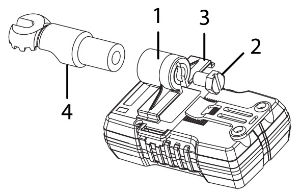 Figure 2 Hot Stick Adaptor Accessories1. Cylinder2. Cylinder screw3. Cylinder bracket4. Universal spline connectorFor instructions on assembling the adaptor, connecting it to the detector, and attaching a hot stick, see Section 6, Using a Hot Stick.
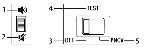 1. Buzzer enabled2. Buzzer muted3. Power OFF position4. Self-Test position5. NCV (non-contact voltage) detection mode
Battery Operation
The DV690 is battery powered and accepts three (3) 1.5 V `AA’ alkaline batteries in the rear compartment. If the detector does not audibly and visibly alert when you move the function switch to the TEST position, replace the batteries and try again. Do not use the detector if it does not power up normally.
![]() CAUTIONAlways install three new batteries of the same make and type. Do not operate the detector if the batteries appear to be damaged, leaking, or otherwise abnormal in their appearance or odor.
CAUTIONAlways install three new batteries of the same make and type. Do not operate the detector if the batteries appear to be damaged, leaking, or otherwise abnormal in their appearance or odor.
- Installing BatteriesThe battery compartment is located on the back of the detector, as shown.Figure 1 Opening the Battery Compartment1. Open the battery compartment by removing the two screws that secure the compartment cover.2. Install three (3) 1.5 V `AA’ alkaline batteries, observing correct polarity.3. Secure the battery compartment cover with the two screws.4. Do not operate the detector until the battery compartment is secured.
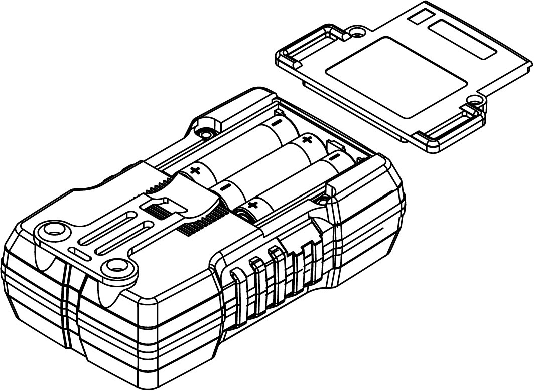 Figure 1 Opening the Battery Compartment1. Open the battery compartment by removing the two screws that secure the compartment cover.2. Install three (3) 1.5 V `AA’ alkaline batteries, observing correct polarity.3. Secure the battery compartment cover with the two screws.4. Do not operate the detector until the battery compartment is secured.
Product Verification Tests
![]() WARNINGBefore use, please perform all verification procedures, below, to ensure correct and safe operation. Failure to observe this warning can cause severe injury or death.
WARNINGBefore use, please perform all verification procedures, below, to ensure correct and safe operation. Failure to observe this warning can cause severe injury or death.
- Automatic Self-Test1. Move the selector switch to the TEST position.2. If the detector is operating normally, the buzzer will sound and the alert LED will light.3. If the buzzer does not sound, or if the alert LED does not light, the detector is not operating normally. In this case, do not use the detector until you have had it evaluated and then either repaired or replaced.
- Manual Verification Test1. Move the selector switch to the NCV position.2. Place a small gauge live wire (100 to 240 V AC) across the detector’s faceplate (between the LED and the buzzer speaker) and observe the behavior of the audible buzzer and visual LED alert. Placing the live wire at a slight angle on the detector’s faceplate can help the detection ability of the detector.3. If the buzzer sounds and the LED lights, the detector is operating normally. Note that the buzzer intensifies when the detected voltage increases.4. If either the buzzer or LED do not activate, then the detector is not functioning normally and should be evaluated and subsequently repaired or replaced.
- Ambient Noise Buzzer TestVerify that the detector’s audible buzzer is sufficient to be heard above the ambient noise in the test area. If you cannot hear the buzzer over the sound of machinery, etc. in the test area, the detector can not fully protect you. The LED will continue to visibly alert you when you are in close proximity to live voltage, however.
Wearing the DV690
The DV690 can be used by simply holding it in hand, but it may be more convenient to wear the detector so your hands are free. The detector can be worn around the neck, on an arm, or clipped to an exposed forward facing jacket pocket or belt during operation.Select the option below that is most appropriate for your application. For best results, the detector should be facing in the direction that you are facing or walking. In addition, use of the supplied protective soft pouch is recommended in dusty or wet conditions.
- Options for Wearing the DetectorCAUTIONThe detector should be worn on the outside of your clothing to minimize false alarm triggers from static electricity discharges.• Belt/Pocket clip. Attach the detector to your belt or pocket (forward-facing) using the clip on the back of the detector.• Neck-strap: Attach the supplied lanyard to the detector’s lanyard slot (see Section 2, Product Description) and wear it around the neck, keeping it outside of the clothing. The lanyard has a safety breakaway coupling mechanism that will detach the lanyard from the detector if it catches on a piece of machinery or other object.• Arm strap. Wear the detector around the arm using the supplied elastic strap. The strap feeds through the slots on the rear of the detector (see Section 2, Product Description).
Using a `Hot Stick’
Use of a hot stick (not supplied) allows you to safely reach into test areas with the detector that you either cannot reach or that are potentially dangerous to access. The supplied hot stick adaptor uses an industry standard `universal spline’ that allows the detector to attach to small or large hot sticks from a variety of manufacturers (for example, the Hastings Model HV3357).
- How to Attach the Detector to a Hot StickFigure 1 Attaching the hot stick adaptor to the DV690.Attach the cylinder (1) to the detector by connecting the cylinder bracket (2) to the slots on the back of the detector.Remove the screw (4) from the spline neck (3), if it’s attached, and slide the universal spline neck (3) into the cylinder (1).Attach the screw (4) to the cylinder (1) to secure the spline to the cylinder and then attach the hot stick to the universal spline connector (5) using a wing-bolt fastener that is typically supplied with the hot stick.
 Figure 1 Attaching the hot stick adaptor to the DV690.Attach the cylinder (1) to the detector by connecting the cylinder bracket (2) to the slots on the back of the detector.Remove the screw (4) from the spline neck (3), if it’s attached, and slide the universal spline neck (3) into the cylinder (1).Attach the screw (4) to the cylinder (1) to secure the spline to the cylinder and then attach the hot stick to the universal spline connector (5) using a wing-bolt fastener that is typically supplied with the hot stick.
Basic Operating Steps
- Install batteries in the rear compartment as explained in Section 3, Battery Operation.
- Perform the product verification steps as described in Section 4, Product Verifications.
- Wear the detector, hold it in hand, or attach it to a hot stick as explained in Section 5, Wearing the DV690 and Section 6, Using a Hot Stick.
- Move the function switch to the NCV position to begin monitoring.
- Perform your normal tasks while the detector monitors your surroundings.
- The alert LED lights and the buzzer sounds when you are in close proxim- ity to live conductors. Refer to Section 8, Distance to Voltage Considerations, for a guideline on approximately how close to the voltage source you’ll be when the visible and audible alarms trigger.CAUTIONStatic electricity can cause the DV690 to trigger; wearing the detector outside of clothing and avoiding contact with the detector will minimize false triggering.
- When you are finished using the detector, turn the function switch to the OFF position and store it in the supplied carry case. If the detector is to be stored for longer than 90 days, remove the batteries and store them separately.
Distance To Voltage Considerations
The information provided below can help you better understand the behavior of the DV690’s alarms based on the distance you are from a variety of voltage sources.![]() CAUTIONThis information is intended for general reference only and is not meant to replace protocols that you may have in place to ensure safety. Always proceed with caution and verify the operation of the DV690 before each use.Refer to Figure 8.1, below, for the examples provided in this item list.
CAUTIONThis information is intended for general reference only and is not meant to replace protocols that you may have in place to ensure safety. Always proceed with caution and verify the operation of the DV690 before each use.Refer to Figure 8.1, below, for the examples provided in this item list.
- Residential meters (240 VAC): Distance between the DV690 and the residential meter is approximately 3.1 to 4 inches (8 to 10 cm) when the alarms trigger.
- Medium voltage pad-mounted transformers (600 VAC): Distance between the DV690 and the transformer is approximately 10 inches (25 cm) when the alarms trigger.
- Distribution pole (7.2 to 14.4 kV AC): Distance between the DV690 and the distribution pole is approximately 2.6 to 5 feet (0.8 to 1.5 m) when the alarms trigger.
- Transmission pole (69 kV AC or higher): Distance between the DV690 and the transmission pole is approximately 10.8 feet (3.3 m) when the alarms trigger.Figure 1 Distance to Voltage Reference Illustration
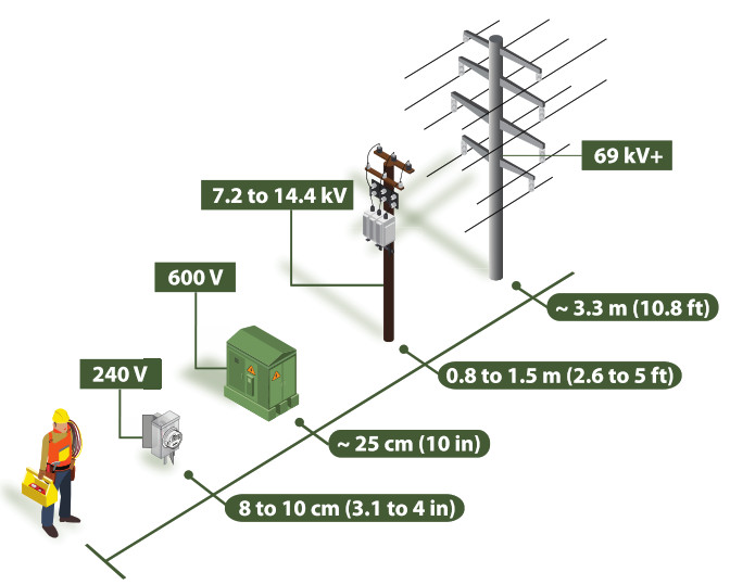 Figure 1 Distance to Voltage Reference Illustration
![]() CAUTIONThe illustration in Figure 8.1 is presented as a general guideline for reference purposes only. The distances are approximations and the voltages may vary by locale.
CAUTIONThe illustration in Figure 8.1 is presented as a general guideline for reference purposes only. The distances are approximations and the voltages may vary by locale.
Specifications
| AC voltage detection range | 100 V AC to 69 kV AC |
| Frequency bandwidth | 50 to 60 Hz |
| Audible buzzer intensity | 106 dB max. (approx.); intensity varies as the detected voltage changes |
| Visual alert | Bright red LED with an intensity of 507 Lux |
| Operating temperature | 14℉ to 104℉ (-10℃ to 40℃) |
| Operating humidity | 10 to 80 RH (non-condensing) |
| Battery power | 3 x 1.5 V ‘AA’ alkaline cells |
| Battery life | 120 hours (continuous use), approx. |
| Safety standard compliance | EN 61326–1 |
| Ingress protection | IP54 |
| Drop test | 4 ft. (1.2 m) |
| Product dimensions | 133 mm (L) x 77 mm (W) x 52 mm (D)5.24 in. (L) x 3.03 in. (W) x 2.05 in. (D) |
| Product weight | 0.49 lbs. (220 g) approx. |
| Supplied accessories | Printed instructions, elastic arm strap, neck-strap lanyard, belt/pocket clip, protective soft pouch, ‘hot stick’ attachment adaptor, three (3) AA batteries, and hard-shell carrying case. |
Two-year Warranty
FLIR Systems, Inc. warrants this Extech brand instrument to be free of defects in parts and workmanship for two years from date of shipment. To view the full warranty text, see the link below. http://www.extech.com/support/warranties
Service and Support
Customer Support Telephone List: https://support.flir.com/contactCalibration, Repair, and Returns e-mail: [email protected]Technical Support: https://support.flir.com
Websitehttp://www.flir.comCustomer supporthttp://support.flir.comCopyright© 2021, FLIR Systems, Inc. All rights reserved worldwide.
DisclaimerSpecifications subject to change without further notice. Models and accessories subject to regional market considerations. License procedures may apply. Products described herein may be subject to US Export Regulations. Please refer to [email protected] with any questions.
Publ. No.: NAS100064Release: AACommit: 73965Head: 73965Language: en-USModified: 2021-02-22Formatted: 2021-02-22
References
[xyz-ips snippet=”download-snippet”]