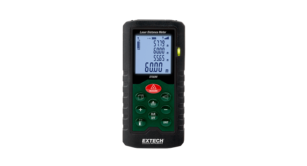
USER MANUALLaser Distance MeterMODELS DT40M, DT60M, and DT100M
Introduction
Thank you for selecting the Extech Laser Distance Meter. This meter measures distance up to 131.2’ (40m) for DT40M, 197’ (60m) for DT60M, or 328.1’ (100m) for DT100M and calculates Area, Volume, and Indirect readings using the Pythagorean Theorem (a²+b²=c² ). It also includes a laser pointer and a stakeout feature. Please visit www.extech.com for the latest version of this User Guide, Product Updates, and Customer Support.
Safety Instructions
This meter has been designed for safe use, but must be operated with caution.
Laser classification (Class 2)The meter produces a visible Class 2 laser beam from the top of the instrument.WARNING: Do not directly view or point the laser at an eye.Do not look directly into the beam using an optical aid such as binoculars. This can create a hazard. Low power visible lasers do not normally present a hazard but may present some potential for hazard if viewed directly for extended periods of time.
- Please read all safety instructions carefully before using this instrument
- Do not use this device inflammable or explosive environments
- Do not use this device near aircraft or medical equipment
- Do not use this device near strong electromagnetic interference
- Do not aim the meter directly into sunlight
- Do not disassemble or modify the instrument
- Do not store in areas of high temperature/humidity
- Remove the batteries when storing the instrument for long periods
Descriptions
Meter
- LCD display area
- Keypad
- Level
- Laser Pointer
- Sensor Beam
Note: Battery compartment on the back of the meter
Display Description
- Length measurement mode
- Battery status
- Datalogger icon and memory location (1~20)
- Signal strength icons
- Laser pointer default mode
- Edge Reference (from top or bottom of a meter)
- Indirect measurements: Single Pythagorean, Double Pythagorean, and Double Pythagorean (partial height)
- Stakeout mode
- Area/Volume mode
- Primary/summary display line
- Auxiliary Display lines 1 (top), 2, and 3
- Units of measure
Keypad Description
| Short press: Power ONShort press: Laser ON (can be set to default ON) Short press: Single distance measurementLong press: Continuous measurement mode | |
 |
Short press: Datalogger mode (press CLR to exit) Long press: Open program menu |
|
Short press: Clear display; Long press: Power OFF |
|
Short press: Area/Volume modeLong press to 1st beep: Stakeout mode |
|
Indirect measurementsPress lx: Single Pythagorean modePress 2x: Double Pythagorean modePress 3x: Double Pythagorean (partial height) |
| Add / Subtract keys | |
 |
Short press: Measurement edge selection Long press: Backlight ON/OFF |
| Short press: Select unit of measure |
Measurement Preparation
Measurement Considerations
- For best results, choose a target that is flat, hard, and smooth2. Use a section of cardboard or similar material if the target size needs to be increased3. For distance measurements, this device performs best indoors. If used outdoors, the range will be limited depending on the intensity of light and other environmental factors.4. Replace the battery if the battery icon flashes on the display5. The meter will not measure through glass, liquid, or Styrofoam6. Inaccurate measurements may result from low battery, a measured distance exceeding specified range, and irregularly shaped objects near the target.
Range considerationsThe range is limited to 131.2’ (40m), 197’ (60m), or 328.1’ (100m) depending on the model. At night or dusk, if the target is in shadow, the measuring range without a target plate is increased.Use a target plate to increase the range during daylight or if the target has poor reflection properties. In unfavorable conditions such as intense sunlight, poor reflective surfaces, or high temperatures, distance readings over 33’ (10m) can increase by ±0.0018in/ft. (±0.15mm/m).Target surfacesMeasurement errors can occur when measuring toward colorless liquids (e.g. water), dust-free glass, Styrofoam, or similar semi-permeable surfaces. Aiming at high gloss surfaces may deflect the laser beam and lead to measurement errors. For non-reflective and dark surfaces, the measuring time may increase.Preparing for Measurements
- Press the MEAS key to switch the meter ON.
- You can select either to have the Laser always ON or to have the laser turn ON only when the MEAS key is pressed. Go to the Programming Menu section of this manual for details.
- The unit automatically switches OFF after three (3) minutes of inactivity. Long press CLR to switch the unit OFF manually.
- Press CLR to cancel the last action performed or clear the last data displayed on the screen.
- Press UNIT to change the unit of measure (ft = feet, in = inches, m = meters.
- Long press
 to turn the backlight on or off.
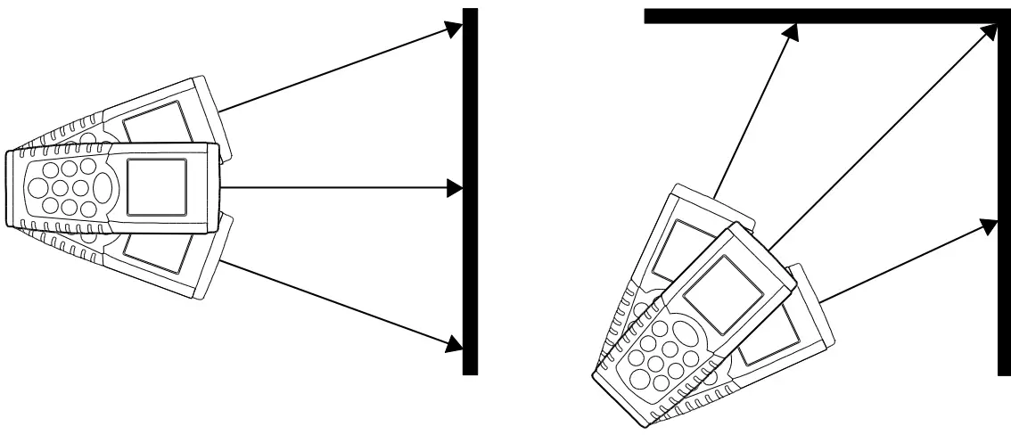
 - Short press the reference key to select the top edge or bottom edge reference. See diagram below.• In the Top mode (2), the displayed reading will represent the distance from the top of the meter to the target.• In the Bottom mode (1), the displayed reading will represent the distance from the bottom of the meter to the target. This is the default mode.

- Long press to open the programming menu
- Use the MEAS button to step through the options
- Use the (+) and (-) keys to make changes
- Use the MEAS button to exit the menu
- See the table below for the program options
| 1 | ON: |
For distance measurements: Set Laser to default ON/OFF. Use + key to select. |
| 2 | For all other measurements: Set Laser to default ON/OFF. Use + key to select. | |
| 3 | CAL. 0 | Use +/- keys to offset display by ±0.3″ (±7mm) |
| 4 | bP. on/oFF | Use +/- keys to set beeper default ON/OFF |
| 5 | bl. On/oFF | Use +/- keys to set backlight default ON/OFF |
| 6 | od. On/oFF | Unused mode |
Distance Measurements
Single Distance Measurements
- Momentarily press the MEASURE key to switch the meter ON; Dashes (- – -) will appear on the display.
- If the Laser point is already ON, go directly to step 3 below. If the Laser point is not ON, press MEASURE to switch it ON.
- Aim the meter and short press MEASURE to take a reading.
- You can select either to have the Laser always ON or to turn it ON only when MEASURE is pressed. Go to the Programming Menu section of this manual for details.
- The reading will remain on the display until it is cleared with the CLR key (short press) or until the meter is powered OFF.
Continuous Distance Measurements (with MAX-MIN)This mode of operation is useful for determining the shortest and longest distances from a given point. The meter can be moved to various targets while the primary display (bottom) updates with each new measurement. The MIN and MAX values are displayed dynamically in auxiliary displays above the primary display.
- Press the MEASURE key to switch the meter ON.
- Press and hold MEASURE for 3 seconds to begin a continuous measurement session. The laser pointer will stay ON in continuous mode.
- The meter will beep with each new automatic measurement update (approx. every one-half second).
- The MIN reading will be indicated (example below, left) and will update each time a lower reading (< displayed MIN reading) is encountered.
- The MAX reading (example below, right) will be indicated and will update each time a higher reading is encountered.
- The actual reading will be indicated on the primary display.
- To stop measuring, short press MEASURE. Use the CLR key to delete measurement displays.
- Note that the meter exits to the normal mode of operation after approx. 100 measurements in continuous mode.
Adding / Subtracting Distance MeasurementsTo display the sum or difference of two distance measurements:
- Press the MEASURE key to switch the meter ON. Press MEASURE to turn Laser ON if it is not already ON.
- Press MEASURE to take the first reading. The reading appears on the primary display line (bottom).
- Press the plus (+) or minus (-) key. The first reading will move to auxiliary display line 2.
- The plus or minus sign will appear on auxiliary display line 3.
- Press MEASURE to turn Laser ON if it is not already ON.
- Press MEASURE to take the second reading. The second reading appears on auxiliary display line 3.
- Read the sum or difference of the two readings on the primary display line.
- Press CLR to cancel the last step or press MEASURE to move the result (now shown in the primary display) to auxiliary display line 2, for additional adding/subtracting work.
- Press CLR to exit this mode or turn the meter OFF.
Area Measurements
Area CalculationsComputing the area of a room:
- Press the MEASURE key to turn the meter ON.
- Press the key firmly once.
- A parallelogram will appear with its length side flashing indicating that a Length measurement is to be taken.
- Press MEASURE to turn Laser ON if it is not already ON.
- Aim the meter and press MEASURE to take the room length measurement.
- The parallelogram will now appear with its Width side flashing indicating that a Width measurement is to be taken.
- Press MEASURE to turn Laser ON if it is not already ON.
- Press MEASURE to take the room width measurement.
- Auxiliary display lines 1 and 2 will now show the Length and Width. The primary display will show the Area (in ft² or m²).
Note that the laser pointer will switch off automatically if too much time is taken between steps. Press MEASURE to switch the Laser pointer back ON and then tries the test again.Adding/Subtracting Area Calculations
- After completing an Area calculation (see the previous section), with the results displayed, short press the (+) key for the ‘summing’ mode or the (-) key for the ‘difference’ mode.
- Perform another Area calculation as explained in the previous section.
- Press MEASURE and the display will show the change (increased or decreased Area) from the first to the second Area calculation in the primary display line (bottom).
Auxiliary displays will show the two individual Area calculations.
Volume Measurements
Volume CalculationsCompute room Volume:
- Press the MEASURE key to switch the meter ON.
- Press the key firmly twice.
- A cube shape will appear with its Length flashing indicating that a Length measurement is to be taken.
- Press MEASURE to turn Laser ON if it is not already ON.
- Press MEASURE to take the room Length measurement.
- The cube’s Width will now be flashing indicating that a Width measurement is to be taken.
- Press MEASURE to turn Laser ON if it is not already ON.
- Press MEASURE again to take the room Width measurement.
- The cube’s Height side will now be flashing indicating that a Height measurement is to be taken.
- Press MEASURE to turn Laser ON if it is not already ON.
- Press MEASURE to take the room Height measurement.
- Auxiliary display lines 1, 2, and 3 will now show the Length, Width, and Height respectively. The primary display
(bottom) shows the Volume in cubic feet or meters (ft³ or m³).Adding/Subtracting Volume Calculations
- After completing a Volume calculation (see the previous section), with the results displayed, short press the (+) key for the ‘summing’ mode or the (-) key for the ‘difference’ mode.
- Perform another Volume calculation as explained in the previous section.
- Press MEASURE and the display will show the change (increased or decreased Volume) from the first to the second Volume calculation in the primary display line (bottom).Auxiliary displays will show the two individual Volume calculations.
Indirect Measurements (Pythagorean)
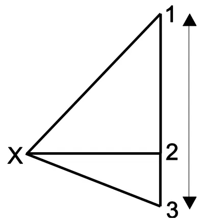
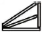
Single Pythagorean Calculation (2 Measurements)This device can measure the vertical height from Point 1 to Point 2 with the operator taking two measurements (Point X to 1 and then Point X to 2).

- Press the MEASURE key to switch the meter ON.
- Press once.
- A right triangle shape will appear with its diagonal line flashing.
- Press MEASURE to turn the Laser ON if it is not already ON.
- From exactly Point X, aim the instrument at Point 1 and press MEASURE. One reading is now complete and the bottom line of the right triangle will begin flashing.
- Press MEASURE to turn the Laser ON if it is not already ON.
- From Point X, align the meter as horizontal as possible and aim for Point 2, and then press MEASURE.
- The measurements are now complete. The primary display line (bottom) indicates the vertical distance from Point 1 to Point 2. Auxiliary lines 1 and 2 show the two separate measurements.
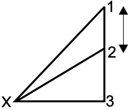
Double Pythagorean Calculation (3 Measurements)This device can measure height in two segments by taking three measurements. The operator stands at Point X. The first measurement is Point X to 1, the second measurement is a horizontal line from Point X to 2, and the third measurement is from Point X to 3.
- Press the MEASURE key to switch the meter ON.
- Press the key two times.
- The double triangle icon will appear with its top diagonal line flashing.
- Press MEASURE to turn Laser ON if it is not already ON.
- From Point X, aim the instrument at Point 1 and press MEASURE. One reading is now complete and the middle line of the double triangle will begin flashing.
- Press MEASURE to turn Laser ON if it is not already ON.
- From Point X, aim the instrument horizontally at Point 2 and press MEASURE. The second reading is now complete and the bottom diagonal line of the double triangle will begin flashing.
- Press MEASURE to turn Laser ON if it is not already ON.
- From Point X, aim the instrument at Point 3 and press MEASURE. The third measurement is now complete.
- The distance from Point 1 to Point 3 will now be indicated on the bottom primary display line. Auxiliary display lines 1, 2, and 3 will show the individual measurements.
Double Pythagorean Calculation (Partial Height)This device can measure the height from Point 1 to Point 2 by taking three measurements. The first measurement is Point X to 1, the second measurement is from Point X to 2, and the third measurement is a horizontal line from Point X to 3.
- Press three times and the icon will display.
- Press MEASURE to turn Laser ON if it is not already ON.
- Press MEASURE to measure from Point X to Point 1.
- Press MEASURE to turn Laser ON if it is not already ON.
- Press MEASURE to measure from Point X to Point 2.
- Press MEASURE to turn Laser ON if it is not already ON.
- Press MEASURE to take a measurement from Point X to Point 3.
- The measurement values for the three sides are shown in the first, second, and third auxiliary displays. If the measurement result conforms to the requirements of thePythagorean Theorem, the calculated height will be displayed in the primary display (bottom); otherwise, an error message will appear.
Notes: Ensure that the measurements are made from the same point. Ensure that the right-angle measurement is made perpendicular to the measured surface.
Stakeout Function
The stakeout function allows you to set up two separate distances (A and B in the diagram below) that can be used independently to mark defined measured lengths (for example, in wood frame construction or fence posting).
- Press MEASURE to switch the meter ON. Set the measurement refers to the front or rear meter edge using the key.
- Press and hold until the first beep.
- On auxiliary display line 1, one digit for value “A” will flash.Set the value of the “A” stakeout distance using the + and – keys to change the value of a digit and MEASURE to move from digit to digit.
- Once the desired value has been set, press to move to “B” on auxiliary display line 2.
- The “B” value will now flash. Use the + and – keys to adjust a digit and the MEASURE key to move from digit to digit.
- Once the desired value for “B” has been set, press to start measuring and marking.
- The third auxiliary display line shows the nearest stakeout point. The primary display (bottom) shows the distance the meter is from the nearest stakeout point.
- Place the meter in position. When the meter is moved slowly along the stakeout line, the primary display (bottom) will decrease or increase (displaying a positive number [no sign] when the measured distance is > the stakeout distance or a negative number [- sign] when the measured distance is < the stakeout distance).
- The meter will start beeping at a distance of 0.1m (3.9”) from the matching dimension. Note that the beep tone is different for negative and positive values. The beeping tone will change when you reach the stakeout distance.
- Mark your locations accordingly.
- Stop the measurement by pressing MEASURE.
20-point Datalogger
This device stores up to twenty (20) readings in memory.
- Take reading as previously described. The reading will automatically be stored in memory location 20.
- Take another reading, the reading that was stored in memory location 20, previously, will move down to location 19 and the new reading will be stored in location 20.
- To view stored readings, press to enter the datalogger mode and use +/- keys to scroll. The memory location number appears at the top of the LCD and the readings appear in the usual primary and auxiliary display lines.
- When scrolling through readings, note that the beeper tone is different for ‘top’ edge reference readings and ‘bottom’ edge reference readings.
- When all twenty locations have been filled the meter begins overwriting the existing readings (starting at location 20)
- Press the CLR key to exit this mode.
Maintenance
WARNING: Do not operate the meter until the battery compartment cover is in place and fastened securely.This instrument is designed to provide years of dependable service if the following care instructions are performed:
- Keep the meter dry and free from dust.
- Use and store the meter in nominal temperature conditions.Temperature extremes can shorten the life of the electronic parts and distort or melt plastic parts.
- Handle the meter carefully and avoid shock and vibration.Dropping the meter may damage the electronic parts or the case. Handle as you would a camera or telescope.
Cleaning
- Do not immerse the instrument in water.
- Wipe the case occasionally with a damp cloth. DO NOT use chemicals, cleaning solvents, abrasives, or detergents. Clean and maintain the instrument lenses in the same manner as for professional camera lenses with high-quality lens wipes.
Battery Installation/ReplacementWhen the low battery symbol appears on the display or when the display does not switch ON, replace the batteries.
- Power OFF before replacing the batteries.
- Open the rear battery compartment.
- Replace the two (2) ‘AAA’ batteries observing correct polarity.
- Replace the battery compartment cover.
Battery Safety
- Use only fresh batteries of the correct type. Remove old or weak batteries so they do not leak and damage the unit.
- If the meter is to be stored for long periods, the batteries should be stored separately to prevent damage to the unit.
- Never dispose of batteries in a fire. Batteries may explode or leak.
- Never mix battery types. Always install new batteries of the same type.
Display Error Codes
For any error, cycle power to see if the error clears. If the error persists after several power cycles, refer to the information below.
|
Display |
Reason |
Action required |
| Calculation error | Re-test | |
| Weak signal reception Measurement time-out | Use target plate | |
 |
Hardware failure | Return for service |
Specifications
General Specifications
| Display | 5-digit (99999) backlit, multifunction LCD |
| Laser diode | Class 2 red laser (wavelength: 635nm) |
| Battery | Two (2) ‘AAA’ alkaline batteries |
| Battery Life | 5,000 measurements (approx.) |
| Backlight APO | After 35 seconds |
| Laser APO | After 35 seconds |
| Meter APO | After 3 minutes |
| IP Rating | IP54 |
| Operating conditions | 32 to 104°F (0 to 40°C) |
| Storage conditions | -4 to 140°F (-20 to 60°C) |
| Dimensions | 4.6 x 2.2 x 1.3 in. (116 x 56 x 32mm) |
| Weight | 3.5 oz. (100g) |
Technical Specifications
| Distance ranges | DT4OM: 2 in. ∼ 131.2 ft. (0.05 ∼40m)DT6OM: 2 in.∼ 197.0 ft. (0.05 ∼60m)DT100M: 2 in. ∼328.1 ft (0.05 ∼ 100m) | ||
| Area calculation range | 999.99 sq. ft. (999.99m2) | ||
| Volume calculation range | 999.99 cu. ft. (999.99m3) | ||
| Resolution | Distance | Area | Volume |
| 0.0 in. | 0.00 ft2 | 0.00ft3 | |
| 0.000m | 0.000m2 | 0.000m3 | |
| 0.00ft | 0.00ft2 | 0.00ft3 | |
| Accuracy | ± 0.08 in. (±2mm) | ||
| Measurement update rate | 0.3 ∼ 3 secs. depending on target reflectivity |
Two-year Warranty
FLIR Systems, Inc. warrants this Extech brand instrument to be free of defects in parts and workmanship for two years from the date of shipment (a six-month limited warranty applies to sensors and cables). To view the full warranty text please visit http://www.extech.com/support/warranties.
Calibration and Repair Services
FLIR Systems, Inc. offers calibration and repair services for the Extech brand products we sell. We offer NIST traceable calibration for most of our products. Contact us for information on calibration and repair availability, refer to the contact information below.Annual calibrations should be performed to verify meter performance and accuracy. Product specifications are subject to change without notice. Please visit our website for the most up-to-date product information: www.extech.com.
Contact Customer Support
report this adCustomer Support Telephone List:https://support.flir.com/contactCalibration, Repair, and Returns: [email protected]Technical Support: https://support.flir.com
Copyright © 2017-2020 FLIR Systems, Inc.All rights reserved including the right of reproduction in whole or in part in any formwww.extech.comDT40_60_100M-en-US_v1.1 12/20
References
[xyz-ips snippet=”download-snippet”]