Extech Mini InfraRed (IR) Thermometer User Manual

For additional languages visit www.extech.com
Introduction
Thank you for selecting the Extech Model IR267 Mini IR Thermometer. The Model IR267 IR thermometer measures and displays non-contact (infrared) temperaturereadings and ambient air temperature. In addition, the Type K thermocouple provides contact temperature measurements. The built-in laser pointer increases target accuracy while the backlit LCD and handy pushbuttons combine for convenient, ergonomic operation. The adjustable emissivity feature allowsthe IR thermometer to measure the temperature of virtually any surface.This device is shipped fully tested and calibrated and, with proper use, will provide years of reliable service. Please visit our website (www.extech.com) for the latest version of this User Manual, Product Updates, Customer Support, and User Manual Translations.
Features
- Measures non-contact surface temperature up to 1112°F (600°C)
- Measures ambient air temperature to 158°F (70°C)
- Type-K thermocouple input offers contact temperature measurements
- 2:1 Distance to Spot Ratio (Field of View)
- Single-point laser targeting
- Automatic Data Hold when trigger is released
- Display Backlight
- MAX/MIN/AVG/DIF temperature recording function
- Selectable temperature units (°F / °C)
- Battery status indication
- Adjustable emissivity
- Visible alarm indication for High and Low Temperature Alarm
- Auto power off approximately 10 seconds after trigger release
Safety
International Safety Symbols
 This symbol, adjacent to another symbol or terminal, indicates the user must refer to the manual for further information
Warnings
- Do not directly or indirectly point the laser at the eyes of a person or an animal
- Inspect for damage or for any shortage of parts or accessories before use
- Replace the battery immediately after the battery indicator flashes
- Do not connect an external probe to live electrical circuits
- Do not submerge in water
- Do not leave the thermometer on or near objects of high temperature
- Do not use the thermometer near explosive gases, steam, or dust
- Note that an object with high reflectivity will normally cause the measured temperature value to read much lower than the actual temperature
- Use the device only as described in this User Guide
Cautions
To avoid thermometer damage, please avoid the following hazards:
- EMF from welding equipment or electro-induction heaters
- Static electricity
- Thermal shock caused by large or abrupt environmental temperature changes; wait 30 minutes to allow the thermometer to stabilize to new environmental conditions
- Do not use this device in excessively high temperature environments
- If the meter is to be stored for a long period of time the battery should be removed to prevent damage to the unit
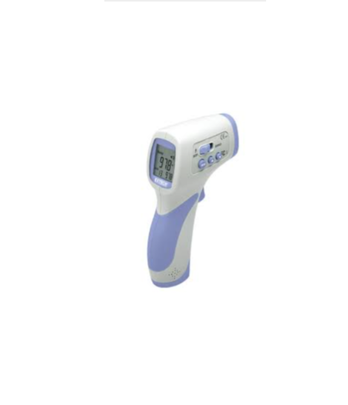
Description
Meter Description
- LCD Display
- Control Buttons
- Lanyard
- Type-K Thermocouple input jacks
- Battery compartment (9V)
- Measurement Trigger
- IR Thermometer lens
- Ambient temperature sensor
- Laser pointer lens
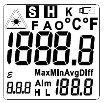
Display Description

Operation
Meter Power
The meter is powered by one 9V battery located in the meter handle. Refer to the Maintenance section for replacement instructions. The displayed battery icon provides battery status. Replace the battery as soon as the battery status icon flashes.
Non-Contact IR Surface Temperature Measurements
The IR267 thermometer remotely measures the surface temperature of an object. The emissivity must be properly set to obtain optimum accuracy (see the Emissivity section for details).
- Hold the meter by the handle grip and pull (and hold) the trigger to power the meter. Use the arrow button to select the O (object/surface) mode if necessary. Scan the surfaces under test; the symbol S (scan) blinks while scanning. Refer to the Field of View section for distance-to-target (spot) ratio considerations.
- Aim the laser pointer approximately a half inch below a specific point of interest.
- Release the Trigger; the symbol H will appear and the reading (larger digits at center of display) will hold for 10 seconds, after which the meter will automatically shut off.
- Note that the smaller digits, lower right, reflect the MIN-MAX-AVG or DIF reading as selected in the Settings mode.
- The meter defaults to the settings in use when the meter was last switched OFF.
Ambient (Air) Temperature Measurements
The IR267 can measure the temperature of ambient air using the recessed temperature sensorlocated on the front of the meter next to the laser pointer lens.
- Pull and hold the Trigger to keep the meter powered.
- Use the UP or DOWN button to select the A (ambient) mode.
- Hold the meter by its handle grip in the ambient air.
- When finished, release the Trigger; the symbol H will appear and the ambient air temperature reading will hold for 10 seconds.
Contact Thermocouple (Type-K) Temperature Measurements
To avoid electrical shock or personal injury, do not connect the external probe to live electrical circuits.
- Plug the Type-K thermocouple sensor into the sub-miniature jacks at the bottom of the instrument (one plug spade is wider than the other).
- Pull the trigger to power the meter. Hold the trigger to keep the meter powered.
- Use the arrow buttons to select the K (thermocouple) mode.
- Hold the thermocouple in air or touch the tip of the thermocouple to an object’s surface. The thermocouple temperature measurement will be displayed.
- When finished, release the Trigger; the symbol H will appear and the thermocouple temperature reading will hold for 10 seconds.
Over-range Indicators (OL and -OL)
If the temperature measurement exceeds 1112°F (600°C), the thermometer will display OL in place of a temperature reading. If the temperature measurement is below -58°F (-50°C), the thermometer will display -OL in place of a temperature reading
Locating Hot or Cold Spots
To detect a hot or cold spot, aim the thermometer at a region beyond the target and then scan the entire region in a slow, up/down motion. Aim the laser pointer approximately a half inch below the point of test.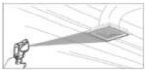
Distance to Spot Ratio (Field of View)
The meter’s field of view is 12:1 (distance to spot ratio). For example, if the meter is 24 inches from the target (spot), the diameter of the target must be at least 2 inches. Other distances are shown below in the field of view diagram. Note that measurements should normally be made < 2 feet from the target. The meter can measure from further distances but the measurement may be affected by external sources of light. In addition, the spot size may be so large that it encompasses surface areas not intendedto be measured.
It is necessary to ensure that the size of the target is larger than the spot size. The smaller the target, the closer the distance should be. See the accompanying diagram.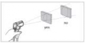
Emissivity
The Emissivity setting is shown in small digits at the lower left corner of the display. To adjust the Emissivity please refer to the Settings mode section. Emissivity represents the reflectivity of a material. Most organic materials and painted or oxidized surfaces have an emissivity of approximately 0.95. If possible, masking tape or flat black paint should be applied to cover the measured surface. Wait a period of time to allow the tape or paint to reach thermal equilibrium with the surface of the covered object. Measure the temperature of the surface covered with tape or paint only after equilibrium has been achieved. Another way to find the emissivity of a surface is to use the Type-K thermocouple to take a contact temperature reading. Note this reading and then take a non-contact temperature reading and adjust the emissivity until the non-contact measurement matches the contact measurement.
Emissivity Factors for Common Materials
Material under test |
Emissivity |
Material under test |
Emissivity |
| Asphalt | 0.90 to 0.98 | Cloth (black) | 0.98 |
| Concrete | 0.94 | Skin (human) | 0.98 |
| Cement | 0.96 | Leather | 0.75 to 0.80 |
| Sand | 0.90 | Charcoal (powder) | 0.96 |
| Soil | 0.92 to 0.96 | Lacquer | 0.80 to 0.95 |
| Water | 0.92 to 0.96 | Lacquer (matt) | 0.97 |
| Ice | 0.96 to 0.98 | Rubber (black) | 0.94 |
| Snow | 0.83 | Plastic | 0.85 to 0.95 |
| Glass | 0.90 to 0.95 | Timber | 0.90 |
| Ceramic | 0.90 to 0.94 | Paper | 0.70 to 0.94 |
| Marble | 0.94 | Chromium Oxides | 0.81 |
| Plaster | 0.80 to 0.90 | Copper Oxides | 0.78 |
| Mortar | 0.89 to 0.91 | Iron Oxides | 0.78 to 0.82 |
| Brick | 0.93 to 0.96 | Textiles | 0.90 |
High and Low Temperature Alarms
The IR267 has a low alarm and a high alarm utility. Set the low and high alarm limits in the Settings mode. See the Settings mode section for details. The low and/or the high alarms can also be disabled in the Settings mode. When the low or high alarm limits are reached the L (low alarm) or H (high alarm) icon will blink and the alarm buzzer will sound (the buzzer can be disabled in the Settings mode.
Settings Mode
Press and release the trigger and then press the M (Mode) button to access the Settings Mode. Use the M button to step through settings listed below and use the SET button to make changes.
- Display mode: Maximum reading (MAX), Minimum reading (MIN), Average reading (AVG),
- Differential reading (DIFF)
- Backlight ON/OFF (LitE)
- Laser pointer (LAS) ON/OFF setting
- High Temperature Alarm Limit setting (ALM H)
- Low Temperature Alarm Limit setting (ALM L)
- Emissivity ( ) setting
- Temperature unit selection (°C/°F)
- Buzzer ON/OFF (bU2)To exit the Settings Mode, press the trigger to return to normal operating mode or simply allow the automatic power OFF feature to switch the meter OFF.
Display Mode: MAX-MIN-AVG-DIFF
Press the trigger and release. Use M Button to step through MAX-MIN-AVG-DIF display mode icons. Press SET when the desired icon is shown. Pull the trigger to return to the normal operating mode. The display (smaller digits lower right) will reflect the selected mode.
Backlight – ON/OFF
Press the trigger and release. Use the M button to step to the LitE display. Press the SET button to select oN or oFF. Pull the trigger to return to the normal operating mode
Laser – ON/OFF
Pull the trigger and release. Use the M button to step to the LAS display. Use the SET button to select oN or oFF. Pull the trigger to return to the normal operating mode. When the laser is ON, the laser icon will appear on the LCD.
HIGH Temperature Alarm Limit Setting
Pull the trigger and release. Use the M button to step to Alm H. Use the arrow buttons to set the High Alarm limit. Press the SET button to turn the High Alarm OFF. Pull the trigger to return to the normal operating mode. If the high alarm limit is exceeded when taking measurements, the displayed ALM H will blink and the alarm buzzer will sound (if ‘bU2’ is set to ON).
LOW Temperature Alarm Limit Setting
Pull the trigger and release. Use the M button to step to Alm L. Use the arrow buttons to set the Low Alarm limit. Press the SET button to turn the Low Alarm OFF. Pull the trigger to return to the normal operating mode. If the low alarm limit is exceeded when taking measurements, the displayed ALM L will blink.
Emissivity Setting
Pull the trigger and release. Use the M button to step to the icon. Use the arrow buttons to adjust the emissivity (in 0.01 steps). The emissivity range is 0.05 to 1.00. Pull the trigger to return to the normal operating mode. For more information, see the Emissivity section.
Selecting the Temperature Unit of Measure (°C/°F)
Pull the trigger and release. Use the M button to step to °C/°F. Use the SET button to select °C or °F. Pull the trigger to return to the normal operating mode and the alarm buzzer will sound (if bU2’ is set to ON).
Setting the Alarm Buzzer ‘bU2’ ON/OFF
Pull the trigger and release. Use the M button to step to ‘bU2’. Use the SET button to select ON or OFF. Pull the trigger to return to the normal operating mode. When set to OFF, the Alarm buzzer will not sound in an alarm condition.
Measurement Notes
- The object under test should be larger than the spot (target) size calculated using the field of view diagram.
- If the surface of the object under test is covered with frost, oil, grime, etc., clean before taking measurements.
- If an object’s surface is highly reflective apply masking tape or flat black paint to the surface before measuring.
- The meter cannot make accurate measurements through transparent surfaces such as glass.
- Steam, dust, smoke, etc. can obscure measurements.
- The meter compensates for deviations in ambient temperature. It can, however, take up to 30 minutes for the meter to adjust to extremely wide ambient temperature changes. 7. To find a hot spot, aim the meter outside the area of interest then scan across (in an up and down motion) until the hot spot is located.
Maintenance
Cleaning
To clean the lenses, use compressed air to clear dust and other particles, then carefully clean with a wet cotton swab. The cotton swab should be moistened with clean water.To clean the meter housing, wipe with a damp, soft cloth. Do not use solvents or abrasives. Do not immerse the IR267 in water or other liquid.
Troubleshooting
Symptom |
Problem |
Action |
| OL display | Target temperature exceeds range | Select a target within range |
| -OL display | Target temperature under-range | Select a target within range |
| Battery icon flashes | Low Battery power | Replace Battery |
| Blank display screen | Low battery power | Check and/or replace battery |
| Incorrect/No displayed value | Wrong measurement function selected | Press Up/Down arrow to selectcorrect measurement function |
| No Laser pointer | Low battery | Ensure that the Laser (LAS) is setto ON in the Settings modeReplace the battery |
| Displayfreezes/undefinedreading | Locked display | Turn the meter OFF then pulltrigger again after 3 seconds |
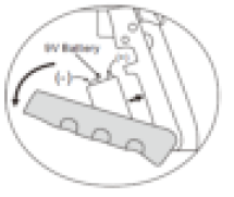
Battery Replacement
When the battery icon flashes, or when the meter doesn’t switch ON, replace the battery:
- The battery compartment is located in the hand grip.
- The battery compartment lid is located just below the trigger.
- Open the battery door by prying with a thumb or finger at one of the indentations near the top of the hand grip.
- The door is hinged at the bottom of the hand grip.
- The battery should be installed with the positive + terminal (smaller contact) facing the meter to ensure correct polarity.
Safety: Please dispose of batteries responsibly; never dispose in a fire, batteries may explode orleak. If the meter is not to be used for 60 days or more, remove the battery and store separately.
Specifications
Temperature Specifications
Temperature Mode |
Object (Surface Mode) |
Ambient (Air) |
Thermocouple (Type K) |
| Range | -58 ~ 1112°F (-50 ~ 600°C) | -4 ~ 158°F (-20 ~ 70°C) | -58 ~ 1832°F (-50 ~ 1000°C)* |
| Accuracy | ± 4.1°F (2.4°C) from -58 ~ 5°F (-50°C ~ -15°C) | ± 3.6°F (2.0°C) from -4~ 158°F (-20°C ~ 70°C) | ± 4.1°F (2.4°C) from -58 ~ 212°F(-50°C ~ -100°C) |
| ± 3.9°F (2.2°C) from 5 ~ 32°F (-15°C ~ 0°C) | |||
| ± 3.6°F (2.0°C) from 32 ~ 212°F(0°C ~ 100°C) | |||
| ± 3%rdg + 1.8°F (1°C) from 212~ 1112°F (100°C ~ 600°C) | ± 3%rdg + 1.8°F (1°C) from 212 ~1832°F (100°C ~ 1000°C) | ||
| Resolution | 0.1 °F/°C | ||
| Emissivity | 0.05 ~ 1.00 adjustable | ||
| Field of View | D/S = Approx. 12:1 ratio (D = distance; S = spot or target) | ||
| Laser pointer | Class 2 laser < 1mW power; Wavelength is 630 ~ 670nm | ||
| IR Spectral response | 8 ~ 14 μm (wavelength) |
| Accuracy is specified for the following ambient temperature range: 73 ~77°F (23 ~ 25°C) |
* The supplied thermocouple is rated for 482oF (250oC) maximum temperature. To measure highertemperatures, please obtain a Type-K thermocouple rated for the desired temperature.
General Specifications
| Display | Backlit multifunction LCD display |
| Display update rate | < 1 second approx. |
| Operating Temperature | 32oF ~ 122oF (0oC ~ 50oC) |
| Operating Humidity | 10 ~ 80% Relative Humidity max. |
| Storage Temperature | -14 ~ 140°F (-10oC ~ 60oC) |
| Power Supply | One 9V battery |
| Automatic Power Off | Meter shuts off automatically after 10 seconds |
| Weight | 4.88 oz. / 138g |
| Dimensions | 6.0 x 4.7 x 1.7” (153 x 120 x 42mm) |
Three-year Warranty
FLIR Systems, Inc. warrants this Extech brand instrument to be free of defects in parts and workmanship for three years from date of shipment (a six-month limited warranty applies to sensors and cables). To view the full warranty text please visit: http://www.extech.com/support/warranties.
Calibration and Repair Services
FLIR Systems, Inc. offers calibration and repair services for the Extech brand products we sell. We offer NIST traceable calibration for most of our products. Contact us for information on calibration and repair availability, refer to the contact information below. Annual calibrations should be performed to verify meter performance and accuracy. Product specifications are subject to change without notice. Please visit our website for the most up-to-date product information: www.extech.com.
Contact Customer Support
Customer Support Telephone List: https://support.flir.com/contact Calibration, Repair, and Returns: Technical Support: https://support.flir.com
Copyright © 2021 FLIR Systems, Inc.All rights reserved including the right of reproduction in whole or in part in any formwww.extech.com
Read More About This Manual & Download PDF:
References
[xyz-ips snippet=”download-snippet”]