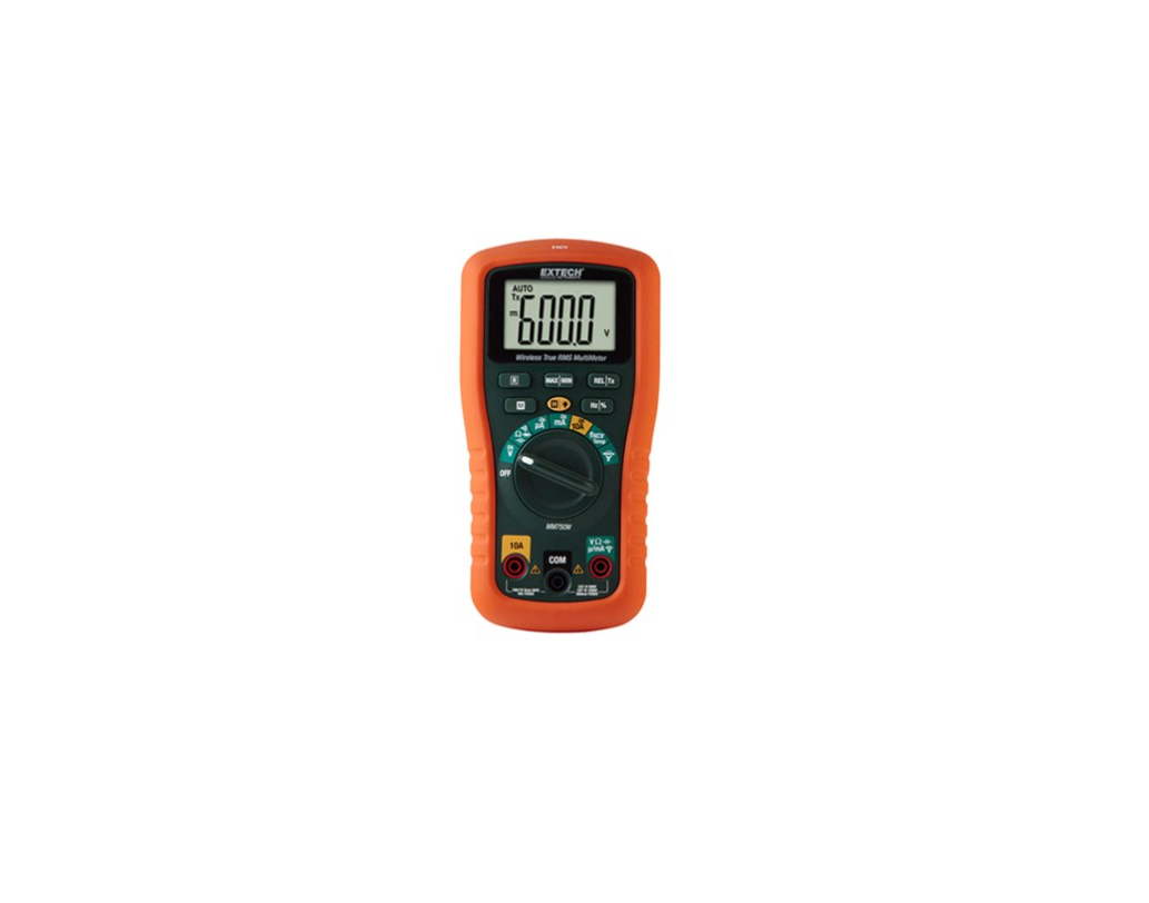
EXTECH MM750W Wireless Datalogging CAT IV True RMS Multimeter User Manual![]()
Introduction
Thank you for selecting the Extech Model MM750W Wireless Datalogging CAT IV True RMS Multimeter. Proper use and care of this meter will provide many years of reliableservice. Please visit our website (www.extech.com) to check for the latest version of this User Manual and Customer Support.
FEATURES
- True RMS responding Auto/Manual Range DMM
- 6000 count (3-3/4 digit) backlit LCD
- Measure AC/DC Voltage and Current, Frequency, Duty Cycle, Capacitance, Continuity, Diode, and Temperature (Type-K thermocouple)
- Non-contact voltage detection
- Accepts external clamp adaptor input
- Data Hold
- MAXIMUM, MINIMUM, and MAX minus MIN recording
- Relative Zero mode
- Auto Power OFF (APO), can be temporarily disabled
- Wireless connectivity with Smart phones and Tablets
- Bluetooth® Wireless Datalogger Module (DAT12) stores over 15k readings for wireless transmission using the ExView® W-Series application
- Rated CAT IV 600V, CAT III 1000V
Safety
This symbol adjacent to another symbol, terminal or operating device indicates that the operator must refer to an explanation in the Operating Instructions to avoid personal injury or damage to the meter.WARNING indicates that a potentially hazardous situation, which if not avoided, could result in death or serious injury.CAUTION indicates that a potentially hazardous situation, which if not avoided, may result damage to the product.This symbol advises the user that the terminal(s) so marked must not be connected to a circuit point at which the voltage with respect to earth ground exceeds (in this case) 1000 VAC or VDC. This symbol adjacent to one or more terminals identifies them as being associated with ranges that may, in normal use, be subjected to particularly hazardous voltages. For maximum safety, the meter and its test leads should not be handled when these terminals are energized.This symbol indicates that a device is protected throughout by double insulation or reinforced insulation.
PER IEC1010 OVERVOLTAGE INSTALLATION CATEGORY
OVERVOLTAGE CATEGORY I
Equipment of OVERVOLTAGE CATEGORY I is equipment for connection to circuits in which measures are taken to limit the transient overvoltages to an appropriate low level.Note – Examples include protected electronic circuits.
OVERVOLTAGE CATEGORY II
Equipment of OVERVOLTAGE CATEGORY II is energy-consuming equipment to be supplied from the fixed installation.Note – Examples include household, office, and laboratory appliances.
OVERVOLTAGE CATEGORY III
Equipment of OVERVOLTAGE CATEGORY III is equipment in fixed installations.Note – Examples include switches in the fixed installation and some equipment for industrial use with permanent connection to the fixed installation.
OVERVOLTAGE CATEGORY IV
Equipment of OVERVOLTAGE CATEGORY IV is for use at the origin of the installation.Note – Examples include electricity meters and primary over-current protection equipment.
CAUTIONS
- Improper use of this meter can cause damage, shock, injury or death. Read and understand this user manual before operating the meter.
- Always remove the test leads before replacing the battery or fuses.
- Inspect the condition of the test leads and the meter itself for any damage before operating the meter.
- Use great care when making measurements if the voltages are greater than 25VAC rms or 35VDC. These voltages constitute a shock hazard.
- Warning! This is a class ‘A’ device. This equipment can cause residential radio signal interference.
- Always discharge capacitors and remove power from the device under test before performing Diode, Resistance or Continuity tests.
- Voltage checks on electrical outlets can be difficult and misleading because of the uncertainty of the connection to the recessed electrical contacts. Use other means to ensure that the terminals are not ‘live’.
- Do not operate this device in a manner not specified by the manufacturer, the protection provided by the equipment may be impaired.
- Do not allow children or pets access to this device, its batteries and other accessories, or the packaging materials.
- If this device is going to be unused for an extended period, remove the batteries.
- Expired or damaged batteries can cause cauterization on contact with the skin. Always use suitable hand protection.
- Do not short-circuit the batteries and do not dispose of batteries in fire.
We designed this device for safe use but please operate with caution. Follow the safety rules, below, for safe operation.
- NEVER apply voltage or current to the meter that exceeds the specified maximum:
- USE EXTREME CAUTION when working with high voltages.
- DO NOT measure voltage if the voltage on the “COM” input jack exceeds 600V above earth ground.
- NEVER connect the meter leads across a voltage source while the function switch is in the current, resistance, or diode position; doing so can damage the meter.
- ALWAYS discharge filter capacitors in power supplies and disconnect the power when making resistance or diode tests.
- ALWAYS turn off the power and disconnect the test leads before opening the covers to replace the fuse or batteries.
- NEVER operate the meter unless the back cover and the battery and fuse covers are in place and fastened securely.
- Do not use the device immediately after moving it from a cold to a warm environment; condensation may form and damage the meter. Leave the device switched off until it has reached room temperature before use.
- Do not use the meter immediately before, during, or after an electrical storm (thunder, lightning, etc.).
- If the equipment is used in a manner not specified by the manufacturer, the protection provided by the equipment may be impaired.
Meter Description
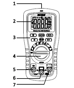
METER FRONT
- Non-Contact Voltage Detector
- LCD
- Control buttons
- Function switch
- Positive 10A input terminal
- COM negative input terminal
- Positive terminal for all inputs except 10A
METER BACK
- Wireless module compartment
- Test lead holders
- Battery compartment
- 600mA/1000V Fuse compartment
- Tilt stand
- 10A/1000V Fuse compartment
Display Symbols
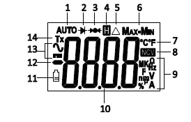
- Automatic range
- Diode test
- Continuity test
- Data hold
- Relative zero
- Maximum-Minimum mode
- Temperature units
- Non-contact voltage detector
- Units of measure
- Measurement display digits
- Low battery icon
- Minus sign
- AC and DC symbols
- Wireless Transmission.
Multimeter Operating Instructions
WARNING: Risk of electrocution. High-voltage circuits, both AC and DC, are very dangerous; please measure with great care.
- ALWAYS turn the function switch to the OFF position when the meter is not in use.
- When Manual ranging, if ‘OL’ appears in the display during a measurement, the value exceeds the selected range. Change to a higher range.
AUTORANGING/MANUAL RANGE SELECTION
The meter defaults to the Auto Range mode. This automatically selects the best range for measurements and is generally the best mode for most measurements. For Manual Range operation:
- Press the R (Range) button. The “AUTO” display indicator will disappear.
- Press the R key to step through available ranges until you select the desired range.
- Long press R to exit to return to Auto Range mode.Note: Manual ranging does not apply for the Capacitance and Frequency functions.
MAXIMUM (MAX), MINIMUM (MIN), and MAX minus MIN modes
Note: The Auto Range function is not available in MAX/MIN mode. Please select the desired range manually before entering MAX/MIN mode. If the reading exceeds that range, ‘OL’ will appear. Auto Range mode will re-activate when you exit MAX/MIN mode.
- Short press MAX/MIN to activate the MAX/MIN recording mode. The display icon “MAX” will appear. The meter will display and hold the maximum reading and will update only when a new “max” occurs.
- Press MAX/MIN again and the display icon “MIN” will appear. The meter will display and hold the minimum reading and will update only when a new “min” occurs.
- Press MAX/MIN again and the display icon “MAX-MIN” will appear. The meter will display and hold the MAX minus the MIN reading.
- Long press MAX/MIN to exit.
RELATIVE ZERO MODE
The relative measurement feature allows you to make measurements relative to a stored reference. In this mode, the displayed value represents the difference between the reference and the measured value. Also, use this button to zero the display by removing stray signals before taking a reading.
- Take a measurement.
- Press the REL button to store the reading; the relative icon will appear.
- The display will then indicate the difference between the stored value and subsequent measurements.
- Press the REL button to exit the relative mode.
LCD BACKLIGHT
Long press the backlight key to switch the backlight ON/OFF.
DATA HOLD
The Data Hold function freezes the reading in the display. Short press the H (Hold) key to activate/deactivate the Data Hold function.
AUTO POWER OFF (APO)
APO will turn the meter off after 5 minutes of inactivity. The meter will emit five audible beeps approximately 1 minute before automatically powering off, after which the meter loudly beeps once as it switches off. To wake the meter, press the M button; no need to turn the rotary switch.To disable APO, press and hold the M button while turning the function switch from the OFF position to any other position. Five (beeps) will sound indicating that the APOfeature has been disabled. Note that the APO will be re-enabled on the next cycle of power to the meter.
LOW BATTERY INDICATION
The battery icon will appear when the battery voltage is critical. Replace the battery before continuing to use the meter.
DC VOLTAGE MEASUREMENTS
CAUTION: Do not measure DC voltages if a motor on the circuit is switching ON/OFF. Large voltage surges may occur that can damage the meter.
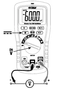
- Set the function switch to the position.
- Use the M (Mode) button to select (DC).
- Insert the black test lead banana plug into the negative COM jack. Insert the red test lead banana plug into the positive V jack.
- Touch the black test probe tip to the negative side of the circuit. Touch the red test probe tip to the positive side of the circuit.
- Read the voltage in the display.
AC VOLTAGE, FREQUENCY, DUTY CYCLE MEASUREMENTS
WARNING: Risk of Electrocution. The probe tips may not reach the live parts inside some 240V outlets. As a result, the reading may show 0 volts when the outlet actuallyhas voltage. Make sure the probe tips are touching the metal contacts inside the outlet before assuming that no voltage is present.CAUTION: Do not measure AC voltages if a motor on the circuit is switching ON/OFF. Large voltage surges may occur that can damage the meter.
DC CURRENT MEASUREMENTS
CAUTION: Do not make 10A current measurements for longer than 15 seconds; Exceeding 15 seconds may cause damage to the meter and/or the test leads. Always turn the meter OFF for 15 minutes before measuring again.WARNING: Never measure current above 600mA in the μA/mA range and 10A in the 10A range. The voltage in the measurement circuit must not exceed 1000VDC
- Insert black test lead banana plug into the negative COM jack.
- For current measurements up to 6000μA DC, set the function switch to the μA position and insert the red test lead banana plug into the μA/mA jack.
- For current measurements up to 600mA DC, set the function switch to the mA position and insert the red test lead banana plug into the μA/mA jack.
- For current measurements up to 10A DC, set the function switch to the 10A position and insert the red test lead banana plug into the 10A jack.
- Press the M button to indicate (DC) on the display.
- Remove power from the circuit under test, then open up the circuit at the point where you wish to measure current.
- Touch the black test probe tip to the negative side of the circuit. Touch the red test probe tip to the positive side of the circuit.
- Apply power to the circuit and read the current on the display.
AC CURRENT, FREQUENCY, DUTY CYCLE MEASUREMENTS
CAUTION: Do not make 10A current measurements for longer than 15 seconds; Exceeding 15 seconds may cause damage to the meter and/or the test leads. Always turn the meter OFF for 15 minutes before measuring again.WARNING: Never measure current above 600mA in the μA/mA range and 10A in the 10A range. The voltage in the measurement circuit must not exceed 1000V AC.
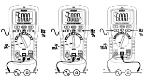
- Insert black test lead banana plug into the negative COM jack.
- For current measurements up to 6000μA AC, set the function switch to the μA position and insert the red test lead banana plug into the μA/mA jack.
- For current measurements up to 600mA AC, set the function switch to the mA position and insert the red test lead banana plug into the μA/mA jack.
- For current measurements up to 10A AC, set the function switch to the 10A position and insert the red test lead banana plug into the 10A jack.
- Press the M button to indicate (AC) on the display.
- Remove power from the circuit under test, then open up the circuit at the point where you wish to measure current.
- Touch the black test probe tip to the neutral side of the circuit. Touch the red test probe tip to the ‘hot’ side of the circuit.
- Apply power to the circuit. Read the current in the display.
- Press the Hz/% button to indicate ‘Hz’. Read the frequency on the display.
- Press the Hz/% button again to indicate ‘%’. Read the duty cycle on the display.
- Press the Hz/% button to return to current measurement
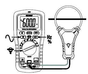
CLAMP ADAPTOR MEASUREMENTS AC/DC
- Turn the rotary switch to the clamp adaptor position .
- Press the M button to indicate AC ‘ ’ or DC ‘ ’ on the display.
- Connect the external clamp adaptor’s negative lead to the meter’s COM jack.
- Connect the external clamp adaptor’s positive lead to the meter’s positive jack.
- The meter displays 1A per each mV input (for example, with a 3mV input, the meter will display 3A).
- Take a current measurement with the external clamp adaptor and read the current on the meter display.
- For AC, Press the Hz/% button to indicate ‘Hz’. Read the frequency on the display.
- For AC, Press the Hz/% button again to indicate ‘%’. Read the duty cycle on the display.
- Press the Hz/% button to return to current measurement.

RESISTANCE MEASUREMENTS
WARNING: To avoid electric shock, disconnect power to the unit under test anddischarge all capacitors before taking any resistance measurements. Remove the batteries and unplug the line cords.
- Set the function switch to the Ω position.
- Insert the black test lead banana plug into the negative COM jack. Insert the red test lead banana plug into the positive Ω jack.
- Press the M button to indicate Ω on the display.
- Touch the test probe tips across the circuit or part under test. It is best to disconnect one side of the part under test so the rest of the circuit will not interfere with the resistance reading.
- Read the resistance in the display.
CONTINUITY CHECK
WARNING: To avoid electric shock, never measure continuity on circuits or wires that have voltage on them.
- Set the function switch to the position.
- Insert the black lead banana plug into the negative COM jack. Insert the red test lead banana plug into the positive jack.
- Press the M button to indicate and Ω on the display.
- Short press the REL button to null any stray resistance.
- Touch the test probe tips to the circuit or wire under test.
- If the resistance is less than approximately 50 ohms, a audible tone will sound. If the circuit is open, the display will indicate ‘OL’.
DIODE TEST
WARNING: To avoid electric shock, never measure diodes that have voltage on them.
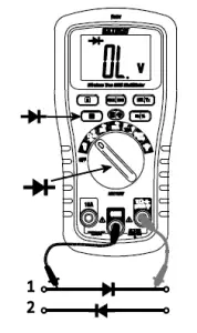
- Set the function switch to the position.
- Insert the black test lead banana plug into the negative COM jack and the red test lead banana plug into the positive V jack.
- Press the M button to indicate and V on the display.
- Touch the test probes to the diode under test. Forward voltage will typically indicate ‘0.400 to 0.700V’. Reverse voltage will indicate ‘OL’. Shorted devices will indicate near‘0V’ and an open device will indicate ‘OL’ in both polarities.
TEMPERATURE MEASUREMENTS
WARNING: The supplied thermocouple range is limited and does not measure over the entire temperature range of the meter.
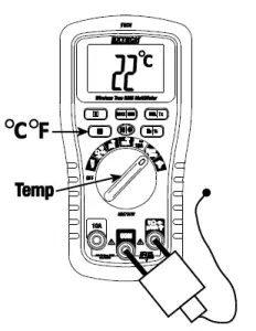
- Set the function switch to the TEMP position.
- Press the M button to indicate oC or oF on the display.
- Connect the Type-K thermocouple to the thermocouple-to-banana adaptor.
- Connect the adaptor’s negative lead to the COM jack.
- Connect the adaptor’s positive lead to the positive jack.
- Touch the Type-K tip to the part under test or leave in open air.
- Read the temperature on the display. Use the M button to select oC or oF.
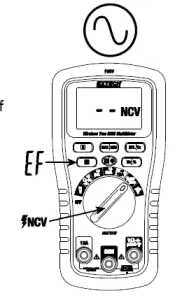
NCV NON-CONTACT (EF) VOLTAGE MEASUREMENTS
WARNING: Check the NCV function on a known live circuit before testing on a circuit of unknown status.
- Set the function switch to the position. The ‘EF’ and ‘NCV’ icons will appear.
- The non-contact voltage detection sensor is located at the top of the meter. Place the sensor near the source of voltage.
- When the meter detects voltage it will audibly beep, the display will blink red, and dashes will appear. The number of dashes is proportional to the strength of the voltage sourceas is the periods between audible beeps. Note that the meter flashes red with each audible beep.
Wireless Communication
WIRELESS COMMUNICATIONS OVERVIEWWe ship the MM750W with a Bluetooth® Wireless Datalogging Module (DAT12) installed in the compartment on the back (top) of the meter. The DAT12 transmits realtime readings and logged readings to paired iOS® or Android™ devices using the free ExView® W-Series application. The DAT12 can record >15k readings.
INSTALLING A WIRELESS MODULE
The communication modules install in the compartment at the back (top) of the meter; see the Meter Description section of this user manual for location. To install a communications module first turn the meter OFF then remove the two Phillips screws that secure the module compartment. Open the compartment, insert the module with the arrow correctly oriented at the top of the module, and connect via the 8-pin connector inside the module compartment. Close the compartment and secure with the two screws before use.
OBTAINING THE APPLICATION (APP)
For iOS devices, download the ExView® W application from the Apple App Store. For Android devices, download the ExView® W application from the Google PlayTM store.
USING THE APPLICATION
- Turn on the meter and select a measurement function
- Long press the Tx button to start the wireless transmission (the Tx display icon will appear when started)
- On your smart device, tap the ExView® W application icon to start the App. (Bluetooth® must be enabled on your smart device)
- Tap the search icon located next to ‘Devices’. The App will search for available devices.
- When the meter appears in the device list, tap it to connect the meter to the App.
- For more information please refer to the ExView® W-Series Help Guide by tapping on the Extech icon and then tapping the Help Guide link, or locate the document on the extech.com/exvieww web page.
- Please note that some Android™ devices require that you switch ON the device’s location setting before the ExView® W app can establish a connection with the wireless meters.
Specifications
Note: Accuracy specifications consist of two elements:
- (% of reading) Accuracy of the measurement circuit.
- (+ digits) Accuracy of the analog to digital converter.
AC Response True RMS responding
Input Impedance > 10M ohm for Voltage AC/DC Ranging Auto/Manual AC Bandwidth 50/60Hz Display 6000-count (3-3/4 digit) backlit LCD Over-range indication ‘OL’ is displayedAuto Power Off After 5 minutes of inactivity (can be disabled) Low Battery Status Battery icon appears when battery < 2.6V Battery One (1) 9-volt battery Fuses ‘mA, μA’ ranges; 600mA/1000V ceramic fast blow ‘A’ range; 10A/1000V ceramic fast blow Operating Temperature 0C to 60C (32F to 140F)5C to 40C (41F to 104F)Storage Temperature -20C to 60C (-4F to 140F)Operating Humidity Max 80% up to 31C (87F) decreasing linearly to 50% at 40C (104F)Storage Humidity <80%Operating Altitude 2000m (7000 ft.) maximum.Weight 415g (14.6 oz.) without batterySize 188 x 96 x 56mm (7.4 x 3.8 x 2.2”)
Safety
This meter is intended for indoor use and protected, against the users, by double insulation per UL 61010-1, 3rd Edition, 2012-04-17 (ELECTRICAL EQUIPMENT FOR MEASUREMENT, CONTROL, AND LABORATORY USE – Part 1: General Requirements)CAN/CSA-C22.2 No. 61010-1, 3rd Edition, 2012-04, (ELECTRICAL EQUIPMENT FOR MEASUREMENT, CONTROL, AND LABORATORY USE – Part 1: General Requirements)IEC 61010-1:2010, 3rd Edition IEC 61010-2-033, Edition 1.0 (2012-04) Approvals
 report this ad
Contact Customer SupportCustomer Support Telephone: U.S. (866) 477-3687; International +1 (603) 324-7800Calibration, Repair, and Returns email: Technical Support: https://support.flir.com
Read More About This Manual & Download PDF:
References
[xyz-ips snippet=”download-snippet”]