
EXTECH® Model 382275 (120V) / 382276 (230V) User Manual
Single Output Laboratory GradeSwitching DC Power Supply
Introduction
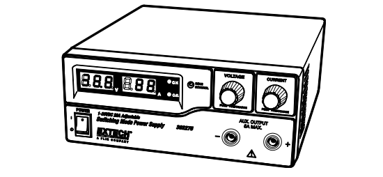
Congratulations on your purchase of the Extech 382275 (120V) or 382276 (230V) Single Output Laboratory Grade DC Power Supply.
The dual action (coarse/fine tune) rotary encoder allows for quick and precise voltage and current level adjustments. Setting, changing, and checking the current limit level can be performed easily without sparking the output poles.
The remote control feature allows the user to remotely perform the following tasks:
- Output power ON/OFF
- Voltage and Current Level Adjustments
The three user-presets facilitate quick access to frequently used voltage and current settings. This power supply is shipped fully tested and calibrated and, with proper use, will provide years of reliable service.
Safety
WARNING
- Do not use this power supply with electric motors or for charging purposes on electroplating equipment or similar devices. Return EMF and voltage transients generated by electric motors can damage this power supply. This power supply was designed for use on electronic equipment only and not intended for use on electrical equipment of any kind.
- Do not use this power supply near water.
- Do not operate or touch this power supply with wet hands.
- Do not open the casing of the power supply when it is connected to AC power.
- Refer all servicing to qualified service personnel only.
- Before replacing the fuse, identify and fix any problems.
- Replace the fuse with a fuse of the specified type and rating.
CAUTION
- Use a grounded 3 pin AC source.
- This unit is intended for indoor use only.
- Do not operate or place this unit in direct sunlight or in a humid location
- Avoid environments where dust or dirt can enter the power supply casing.
- Do not place the power supply near a heat source.
- Before plugging into local AC mains, check the rating label at the back of the unit for 120V or 230V operation. The model 382275 can be powered by 120V only. The model 382276 can be powered by 230V only.
- Do not block the ventilation openings of the unit.
- This unit must be used within the specified rating; excessive continuous loading may cause damage to the power supply.
- The gauge size of the input power cable must be at least 3 “(0.75mm) and the total length of power cable must not exceed 118” (3m)
Power Supply Description
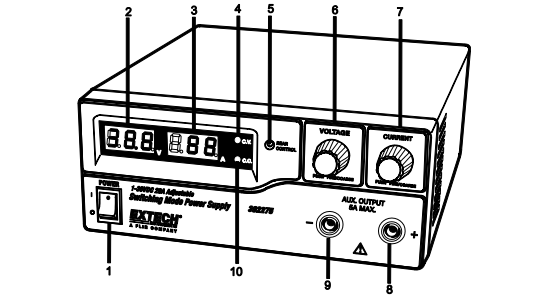
- Power Switch ON/OFF
- Voltage Display
- Current Display
- Constant Voltage Indicator LED
- Rear Control Indicator LED (Switches ON when in Preset, Remote Control or Set Mode)
- Output Voltage Control Knob (Controls both the main and auxiliary output voltage)
- Output Current Control Knob (Controls both the main and auxiliary output current)
- Positive Auxiliary Output Terminal (Max. 5 Amps)
- Negative Auxiliary Output Terminal (Max. 5 Amps)
- Constant Current Indicator LED
Rear Panel Description
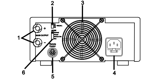
- Main Output (20 Amps Max.)
- P1, P2 and P3 Recall Switch
- Cooling Fan for Ventilation
- AC input Plug and Fuse
- Remote Control Connector
- Mode Switch
Mode Descriptions
Mode Selection
The power supply has four (4) modes of operation: NORMAL, PRESET, SET and REMOTE CONTROL mode. Slide the Mode Selection Switch to the desired Mode. The power supply defaults to the NORMAL Mode.
Normal Mode
Normal Mode is the factory preset mode. The power supply’s output voltage and current are controlled by the dual action volume knobs. Push the knobs to toggle the coarse and fine tuning; notice the subtle changes in brightness of the related LED. Adjust the knob to the desired value first with the Coarse adjustment and then with the Fine tune adjustment. Turn the Current knob gently in any direction to check the preset current level. The display will resume its normal brightness after a few seconds to confirm the adjustment.
Preset Mode
In the PRESET mode, the Rear Control Light is switched ON to indicate that the panel voltage and current controls are de-activated.
There are three preset outputs, P1, P2 and P3, selectable via the Recall Switch, located on the rear of the power supply.
The preset values are factory set per the following table.
| Presets | Output Voltage | Output Current |
| P1 | 5V | Maximum |
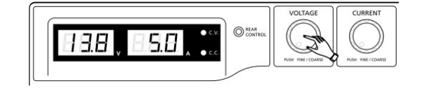
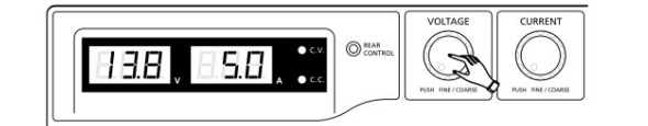
| P2 | 13.8V | Maximum |
| P3 | 25V | Maximum |
Set Mode
In the SET mode, the Voltage and the Current values for the three presets (P1, P2, and P3) can be programmed.
- Set the Mode Switch located on the rear of the power supply to the “SET” position.
- Select a preset using the Recall Switch (set to the P1, P2 or P3 position).
- Use the front panel Voltage Control Knob to set the desired voltage value.
- Use the front panel Current Control Knob to set the desired current value.
- Repeat this procedure for the remaining presets if desired.
- Move the Recall Switch from the SET to the PRESET position to store changes.
Note: Presets reside in non-volatile memory meaning that the voltage and current settings for each preset are retained even when the power supply is switched OFF.
Caution: Check the output voltage of the preset in use before connecting to the Load. To check a preset value, move the Mode Switch to the PRESET position and then move the Recall Switch to the P1, P2 or P3 position. The Voltage and Current settings for the corresponding preset will display.
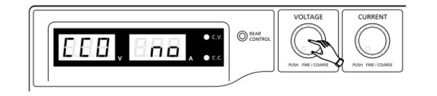
To reset the preset outputs to the factory default state:
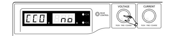
- Press and hold the Voltage Control knob for 30 seconds to access the menu.

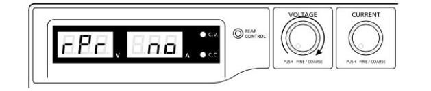
- When the display is showing `CCO’, rotate the Voltage Control knob until the voltage meter shows `rPr.
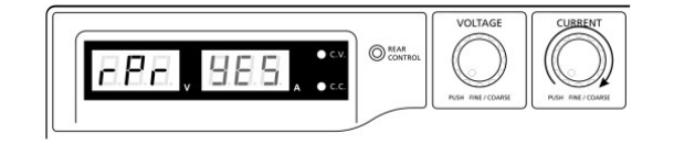
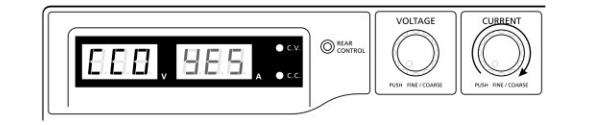
- With the Current meter showing `no’, rotate the Current Control knob until the Current meter shows `YES’.
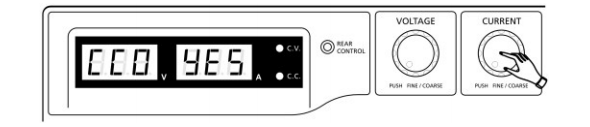
- Press the Current Control knob once to confirm.
- Press the Voltage Control knob to exit the menu

Power up Checks
- First, check the rating label of the power supply and make sure it complies with the AC mains voltage (120V or 230V). Next, set the Mode Switch located on the rear of the power supply to the Normal Position.
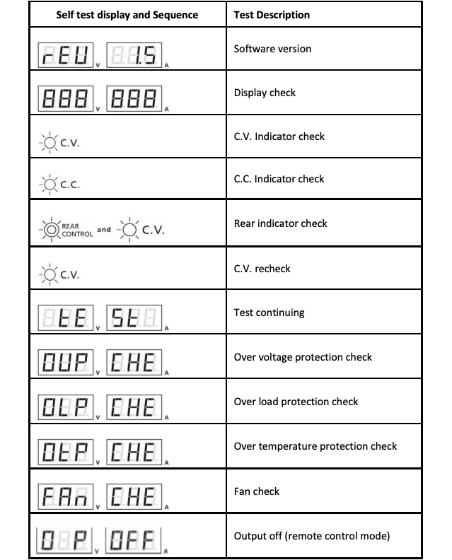
- Listen for the cooling fan when switching on the power supply. The power supply performs a series of self test checks on startup which includes testing the cooling fan. The fan will stop completely after a few seconds after running at high speed indicating that it is in good order. The CV, V and A lights switch ON displaying voltage and 0.0 current. To check the current level, turn the control knob one click in either direction. The current display returns to 0.0 after a few seconds.
The Table below illustrates the Self-Test sequence:
Operation
WARNING: Do not use this power supply with electric motors for any reason or for charging purposes on electroplating equipment or similar devices. Return EMF and voltage transients generated by electric motors can damage this power supply. This power supply was designed for use on electronic equipment only and not intended for use on electrical equipment of any kind.
Using the Control Knobs
The rotary control knobs offer fine/coarse tuning with notched movement.
- Push the knobs to toggle between coarse and fine tuning, notice the subtle changes in brightness of the related LED.
- Adjust the knobs to the desired values by using coarse and then fine tuning. The display will resume its normal brightness after a few seconds to confirm the adjustment.
Connecting to UUT (Unit under test)
- Connect the equipment to the power supply. Red (+) is connected to the positive polarity input of the UUT and Black (-) is connected to the negative polarity input of the UUT.
- Switch ON the power supply first; the panel meter & green CV Indicator should switch ON.
- Switch ON the UUT; the panel meter & green CV Indicator should remain on.
- The UUT is now ready. When operation is completed, switch off the UUT and then the power supply.
- When disconnecting the power supply from the UUT, disconnect the remote sensing wire first and then disconnect the output cables.
Manual Zero Function
The power supply automatically zeroes the current metering upon power-up. To manually run a zero function without having to cycle power:
- Press and hold the Voltage Control Knob for 30 seconds to open the menu.
- Rotate the Current Control knob until the meter shows the following:
- Press the Current Control knob once to confirm. The display will show `YES’.
- Press the Voltage Control knob to exit the menu.
Remote Control
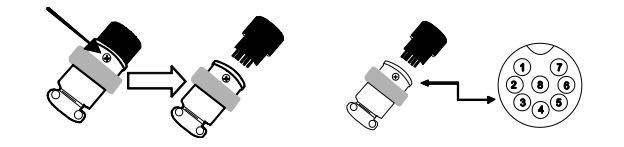
Remote control is made possible through the use of the supplied 8-pin Remote Control connector and 22AWG wire. The Remote Control feature offers remote adjustment of voltage and current and output ON/OFF switching.
Remote ON-OFF Control
The Remote Control ON-OFF function can be activated in any of the operational modes (NORMAL, PRESET, REMOTE, and SET). Using the supplied 8-pin plug and 22AWG wire, follow the procedures below:
- Remove the black portion of the remote control connector plug by removing the screw as shown.
- If PIN 5 is open, the output is ON.
- If PIN 5 is shorted to ground (PIN 4) the output is OFF.
- When the output is OFF, the C.V. & C.C. LED will flash. The current output voltage and current setting will show on the panel meter.
- The output voltage & current control knob can be used to adjust to the desired value when the output is off.
Remote Voltage/Current Control
There are two methods (Method A and Method B; see below) for the remote adjustment of voltage and current. Each method requires that the Current remote control portion be functional otherwise the unit will be in the CC mode all of the time.
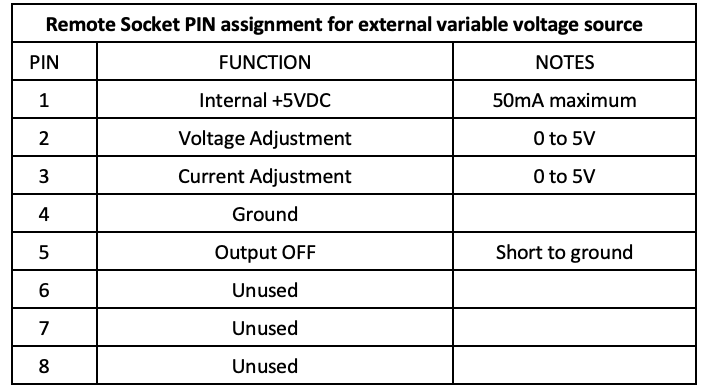
Remote Control Method A: Using two external variable DC voltage sources
A variable external voltage source of 0 ~ 5VDC is fed into the remote control terminal to adjust the output voltage level.
Warning! Do not input voltage higher than 5V, otherwise the Over Voltage Protection (OVP) will be triggered.
- Ensure that there are no connections to the main power supply output terminals and that the power supply is OFF.
- Testing the Voltage control Use ONLY the Voltage control from Pin 2 (Positive) and Pin 4 (Ground).
- Switch ON the power supply.
- Vary the voltage control from 0~5V to check and verify the full output voltage range of the supply as observed on the Voltage display.
- Switch OFF the power supply.
- Testing the Current control –Short the power supply main output terminals with a 10AWG wire.Turn up the Voltage control to maximumTurn the Current control to minumumTurn ON the power supplyTurn up the current control and observe the Current Display.Turn down the current control
- Switch OFF the power supply Remove the short from the main ouput terminals
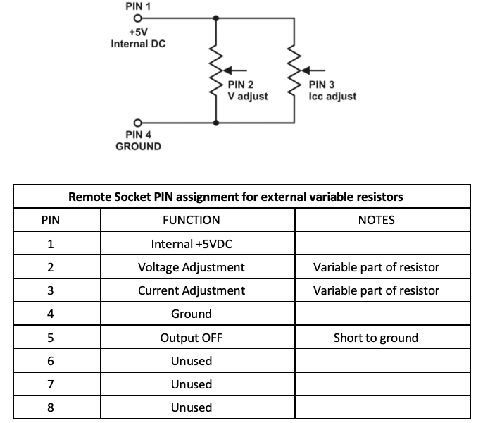
Remote Control Method B: Using two external variable 5k ohm resistors
- Ensure that there are no connections to the main power supply output terminals and that the power supply is OFF.
- Prepare two 5k ohm variable resistors as shown in the diagram below and use the wires from Pins 1, 2, 3 and 4 as shown.
- Switch the power supply ON.
- Vary the Pin 2 variable resistor from one end to the other end to check and verify the full output voltage range of the power supply as observed on the Voltage display.
- Turn off the Power supply.
- Testing the Current control –Short the power supply main output terminals with a 10AWG wire.Turn up the Voltage control to maximumTurn the Current control (Pin 3 resistor) to minumumTurn ON the power supplyTurn up the current control and observe the Current Display.Turn down the current control
- Switch OFF the power supply. Remove the short from the main ouput terminals
Overload Protection
OUP: Over Voltage Protection

This unit has a built-in over-voltage protection feature. In the event of an output voltage exceeding the allowable range (refer to the specifications section for range limits), protection will be triggered and the output power will be switched off. (OUP warning appears).
To reset the warning, switch off the power supply and remove all loading. Switch the unit to resume normal operation. If this problem persists, please contact Extech Technical Support.
OTP: Over Temperature Protection

The unit houses a thermo-sensor that monitor to determine if an over-heating condition exists. The OTP warning will appear on the display and the output will switch off in over-heating condition does exist. When this warning appears, switch off the unit and remove all loading.
In these cases, check the load and the output settings and then allow the unit to cool for at least 30 minutes.
Ensure that the ventilation openings are not blocked and that the power supply has proper clearance. Ensure that the cooling fan is operational; never use the power supply with a faulty cooling fan.
OLP: Over Load Protection

Normally the overload protection is provided by the CC constant current mode. However, if the CC mode fails it may cause serious damage to the test piece or to the load. OLP is used to minimize the extent of the damage to the load. Switch off the power supply as soon as this warning appears. To reset this warning, switch off the unit and remove all loading and then switch the unit on again. If this problem persists, please contact Extech Technical Support.
Maintenance and Repair Services
Cleaning the meter housing
Prior to cleaning the meter housing, disconnect the mains plug from the power outlet. Clean only with a damp, soft cloth and a commercially available mild household cleaner. Ensure that no water gets inside the equipment to prevent possible shorts and damage to the equipment.
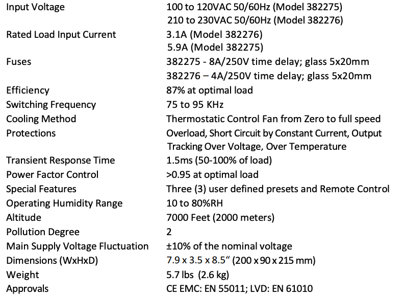
Specifications

Two-year Warranty
FLIR Systems, Inc. warrants this Extech brand instrument to be free of defects in parts and workmanship for two years from date of shipment (a six-month limited warranty applies to sensors and cables). To view the full warranty text please visit: http://www.extech.com/support/warranties.
Calibration and Repair Services
FLIR Systems, Inc. offers calibration and repair services for the Extech brand products we sell. We offer NIST traceable calibration for most of our products. Contact us for information on calibration and repair availability, refer to the contact information below. Annual calibrations should be performed to verify meter performance and accuracy. Product specifications are subject to change without notice. Please visit our website for the most up-to-date product information: www.extech.com.
Contact Customer Support
Customer Support Telephone List: https://support.flir.com/contactCalibration, Repair, and Returns: [email protected]Technical Support: https://support.flir.com
Copyright © 2021 FLIR Systems, Inc.All rights reserved including the right of reproduction in whole or in part in any formwww.extech.com
References
[xyz-ips snippet=”download-snippet”]