EXTECH Tone Generator and Amplifier Probe

Introduction
Congratulations on your purchase of Extech’s Model 40180. This tone generator and amplifier probe set is used to quickly trace and identify cables or wires within a group and also to check the operation of phone lines. With proper use and care, this meter will provide many years of reliable service.
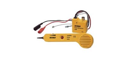
Meter Description
- Power switch
- Modular connectors
- Test leads
- Battery compartment (rear)
- Probe tip
- Volume/Sensitivity control
- Power button
- Battery compartment (rear)
- Headphone jack
Operating Instructions
Note: Remember to turn off the tone generator after tracing the cablesCable/Wire tracingCAUTION:Do not connect the tone generator in the TONE position to any wire or cable with an active circuit of more than 24VAC.
- Connect the tone generator to the cablea) For cables terminated at one end, connect the red alligator clip to a wire and the black alligator clip to equipment groundb) For unterminated cables, connect the red alligator clip to one wire and the black alligator clip to another wire.c) For cables with modular connectors, plug the RJ11 or RJ45 connectors directly into the mating cable connectors.
- Set the tone generator power switch to the TONE position.
- On the amplifier probe, press and hold the side on/off switch.
- Hold the insulated probe tip against the wire in question to pick up the signal generated by the tone generator.
- Rotate the volume/sensitivity control on the top of the probe for the appropriate level and sensitivity to identify and trace the wire.
- The tone will be the loudest on the wires connected to the tone generator.
Note: RJ11 tests are performed on one pair only and RJ45 tests are performed on pins 4 and 5.Note: A headphone jack is located on the bottom of the probe.
Identifying telephone cable Tip and Ring Using Alligator Clips1. Switch the tone generator to the OFF position2. Connect the red test lead to one line and the black lead to the other line.3. The LED color indicates the connection to the RED test lead as:GREEN = Ring side, RED = Tip side.
Identifying telephone cable Tip and Ring Using the RJ-11 or RJ-45 Connectors1. Switch the tone generator to the OFF position2. Connect the RJ-11 or RJ-45 connector mating cable connector.3. The LED color indicates the condition of the telephone jack wiring.GREEN = Jack wired properly, RED = Jack wired with reversed polarity.
Identifying telephone cable Line Condition1. Switch the tone generator to the OFF position2. Connect the red test lead to the RING side and the black test lead to the TIP side.3. The LED will indicate line condition by:GREEN = CLEAR , OFF = BUSY, Flickering YELLOW = RINGING4. Switch the tone generator power switch to CONT to terminate the call.
Continuity testingCAUTION: Do not connect the tone generator in the CONT position to any wire or cable with an active circuit.1. Connect the test leads to the wire pair under test.2. Switch the tone generator to the CONT position.3. The LED will glow bright GREEN for a low resistance or continuity. The LED will glow less brightly as the resistance increases and will extinguish at approximately 10,000 ohms.
Tone selectionThe output of the tone generator can be set to continuous or wobble. To change the type of output, change the tone type switch position (located in the battery compartment)
Battery replacementInstall a new battery by removing the battery cover as indicated in the meter description diagram.
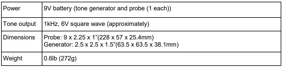
Specifications
Two-year WarrantyFLIR Systems, Inc. warrants this Extech brand instrument to be free of defects in parts and workmanship for two years from date of shipment (a six-month limited warranty applies to sensors and cables). To view the full warranty text please visit: http://www.extech.com/support/warranties.
Calibration and Repair ServicesFLIR Systems, Inc. offers calibration and repair services for the Extech brand products we sell. We offer NIST traceable calibration for most of our products. Contact us for information on calibration and repair availability, refer to the contact information below. Annual calibrations should be performed to verify meter performance and accuracy. Product specifications are subject to change without notice. Please visit our website for the most up-to-date product information: www.extech.com.
Contact Customer SupportCustomer Support Telephone List: https://support.flir.com/contactCalibration, Repair, and Returns: [email protected]Technical Support: https://support.flir.com
Copyright © 2021 FLIR Systems, Inc.All rights reserved including the right of reproduction in whole or in part in any formwww.extech.com
References
[xyz-ips snippet=”download-snippet”]