FAKRO Z-Wave Roller Shutter User Manual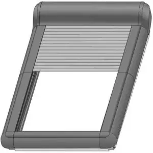
Dear Sir/Madam! Thank you for purchasing the product from FAKRO. To ensure appropriate functioning of the product, please peruse this User Manual.
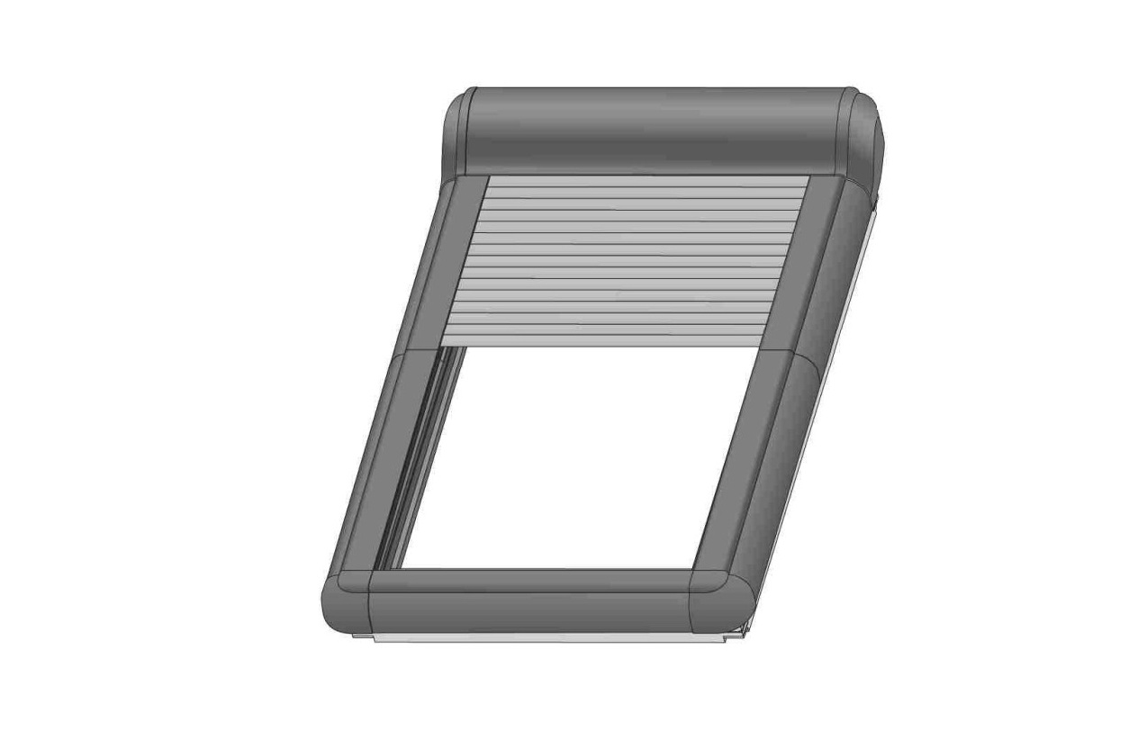
ROLLER SHUTTER DESCRIPTION
The ARZ Z-Wave M roller shutter is designed for installation on roof windows and adapted for cooperation with Z-Wave remote control system elements with frequency depending on part of the world.
The ARZ Z-Wave M roller shutter comes with the following protections:
- Electronic limit switch – when the roller shutter armour is fully unrolled or rolled up.
- Current limiting to provide protection against damage in the event of an obstacle or when running a snow-covered roller shutter at low temperature.
The functionality of the roller shutter allows the percentage read of the current position in the range of 0-100% by the controller with an indicator.To operate the roller shutter, it is required to install it following the picture installation instructions included in the product packaging and assign to the Z-Wave controller. The controller* must be purchased separately.
|
|
|
IMPORTANT INFORMATION
Please read carefully the instructions below before proceeding to product installation so as to prevent electric shock, injury, etc. It is required to observe the following recommendations when installing electrically operated roller shutter:
- After unpacking, check the roller shutter elements for any signs of mechanical damage.
- Installation should he performed by a qualified person in accordance with manufacturer’s instructions.
- Before connecting the roller shutter, make sure that the power supply corresponds with motor voltage specified on the data plate.
- Take the roller shutter out of the packaging, place in flat position and connect it (2-wire cable — 15V DC). Check its correct operation with one working cycle using manual control button.
- Plastic containers used for packing should be stored out of children reach as they may be a potential source of danger.
- The roller shutter should be used according to its intended design. FAKRO shall not be responsible for any consequences being the result of improper roller shutter use.
- Any activities related to cleaning, adjustment or dismantling the roller shutter should be preceded with disconnecting the power supply.
- The roller shutter cannot be washed using solvent-based substances or open stream of water (do not immerse it in water).
- Any repairs of the roller shutter should be carried out by service authorised by the manufacturer.
- The roller shutter is intended for outdoor installation.
- In the event of adverse weather conditions (frost, snow) it may not be possible to operate the roller shutter.
- The roller shutter has been factory calibrated. If, after some time, it is necessary to calibrate the roller shutter, it must be performed manually or via a remote control as described in the “Roller Shutter Programming” section.
CONTROLLER – Z-Wave device such as remote control, module, wall switch, internet gateway. t, • •
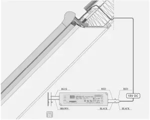
CONNECTION DIAGRAM
CONTROL PANEL
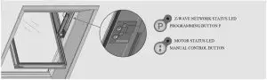
Z-WAVE NETWORK STATUS SIGNALLING
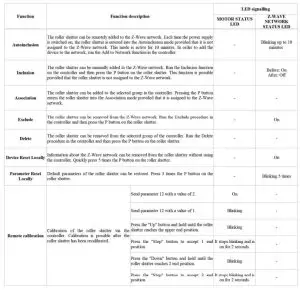
- The roller shutter in the Autoinclusion mode is ready to be remotely added to the Z-Wave network. Run the procedure of adding the roller shutter on the Z-Wave controller.

- The roller shutter has been removed from the Z-Wave network. Remote control of the roller shutter is not possible.
- Cause 1: The roller shutter is assigned to the Z-Wave network. Remote control of the roller shutter is possible.Cause 2: No power supply or no connection to the source of power supply.


PROGRAMMING
For programming information refer to the user manual of the controller which is to control the roller shutter.
ADD TO NETWORKADD TO GROUP REMOVE FROM NETWORK REMOVE FROM GROUP etc.
Run selected function on the Z-Wave controller.
- METHOD 1The Autoinclusion procedure has been started. The roller shutter will be automatically added to the Z-Wave network.
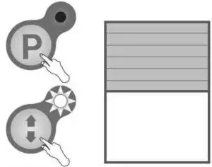
- METHOD 2Press the P button on the roller shutter.


It allows a hard-to-access roller shutter to be remotely added to the Z-Wave network without the need for pressing the programming button. Each time the power is switched on, the roller shutter enters the Autoinclusion mode provided that it is not assigned to the Z-Wave network. The mode is active for up to 10 minutes.
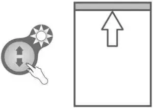
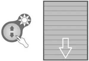
MANUAL CONTROL
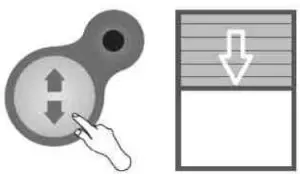
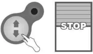
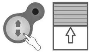
Operate the roller shutter by pressing the manual control button. I. Stan, 2. Stop. 3. Start in the opposite direction…
MANUAL CALIBRATION
The roller shutter is factory calibrated. If necessary, the calibration process can be repeated. If the roller shutter is not calibrated, the control is possible only by holding the manual control button.
- Hold the buttons simultaneously until the manual control LED starts blinking.
- Hold the manual control button until the upper end position is reached. The roller shutter will overload and then retract by 1 cm.
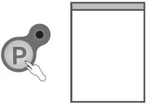
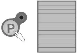
- Accept the upper position by pressing the programming button.
- Hold the manual control button until the lower position is reached. Then release the button.
- Accept the lower position by pressing the programming button. The roller shutter calibrated.
ADDITIONAL INFORMATION
ALL ON / ALL OFF
Turning on the function makes it possible to control all devices simultaneously. The function is available if supported by the controller.
Z-WAVE DEVICES COMPATIBILITY
The Z-Wave makes it possible to integrate devices of different manufacturers (lighting, heating, domestic automatic control, etc.). The Z-Wave devices operate as repeaters in the network which extends the communication range of radio waves.This product is compatible with other certified Z-Wave devices of other manufacturers. All battery-free devices of different manufacturers operating in one Z-Wave network can route through other devices, which can result in increased range.
Note: All information on adding devices to the Z-Wave network in controllers offered by other manufacturers can be found in user manuals of these products.
ASSOCIATION GROUPS
- Life Line — group for reporting the position of the roller shutter after each stop and receiving information about the alarm (overload).
- maximum of 1 device can be in the group.
- Basic Repeat — group used for sending received commands of movement (BASIC SET) to devices belonging to this group. A maximum of 5 devices can be in the group.
- Multilevel Repeat — group used for sending received commands (SWITCH MULTILEVEL SET, SWITCH MULTILEVEL START LEVEL CHANGE, SWITCH MULTILEVEL STOP LEVEL CHANGE) to devices belonging to these groups. A maximum of 5 devices can be in the group.
Z-WAVE PROCEDURE DESCRIPTION
PROBLEMS & ERROR CODES
| Voltage during operation | Roher shutter closing | Roher shutter opening |
| I IV— 11.fiV | LED blinking twice every 2 seconds. | LED blinking twice every 2 seconds. |
| <l1V | The roller shutter stops alter 5 second—s LED blinking three times every 2 seconds and sending an alarm | The roller shutter stops after fi second—s LED blinking three times every 2 seconds and sending an alarm. |
| Pre-start voltage | Roller shutter closing | Roher shutter opening |
| HV— 11.8V | Operation is not allowe—d LED bLnking twice and sending an alarm. | Operation is allowed— LED blinking twice every 2 seconds. |
| < HV | Operation is not allowe—d LED bLnkinq rwice and sending an alarm. | Operation is allowed— the roller shutter stops afier second—s LED blinking twice every 2 seconds and sending an alarm— the roller shutter can be opened in steps. |
| 11V< | High voltage lock: If the supply voltage is higher than 16V, the controller blocks the possibility of starting the motor. This is indicated by the motor status LED blinking quickly nvice which means ‘incorrect supply voltage’. |
Z-WAVE CONFIGURATION PARAMETER
| Parameter | value | Default value | Size | Description |
| 12 | 2 | 1 | 1 |
|
| 13 | 2 | 1 | 1 | FF go to previous position |
| 99 | 2 | 1 | 1 | restoring all parameters to factory settings. If there is 2 in the report. it means that one of ihe parameters has a value other than the default one |
| 100 | 2 | 1 | 1 | auto exclude |
ALARMS & NOTIFICATION
| Notification type | Event |
| Energy management | Overload |
| System | System device failure (defective encoders) |
MANUFACTURER SPECIFIC REPORT
| Parameter | Value |
| Manufacturer ID | 0x008 |
| Product Type ID | 0x0003 |
| Product ID | 0x0111 |
COMMAND CLASSES
| Command Classes | Role | |
| Support | ||
| Command Class Z-Wave* Info v2 | ok | |
| Command Class Basic v1 | ok | ok |
| Command Class Version v2 | ok | |
| Command Class Manufacturer Specific v2 | ok | |
| Command Class Device Reset Locally vl | ok | |
| Command Class Association v2 | ok | |
| Command Class Association Group Info vl | ok | |
| Command Class Powerlevel v1 | ok | |
| Command Class Switch Binary vl | ok | |
| Command Class Switch Multilevel v3 | ok | ok |
| Command Class Switch All v1 | ok | |
| Command Class Configuration v1 | ok | |
| Command Class Notification v3 | ok | |
| Command Class Node Naming v1 | ok |
WARRANTY
The manufacturer guarantees correct device functioning. The manufacturer also undertakes to repair damaged device if the damage results from defects in materials and structure. The warranty period is 24 months from the date of purchase, fulfilling the following conditions:
– Installation has been performed in accordance with the manufacturer’s recommendations. – No unauthorised structural changes have been made. – The device has been used in accordance with its intended use as per user manual. – Damage is not a result of improperly made electrical system or atmospheric phenomena. – The manufacturer is not liable for damage which occurred as a result of improper use or mechanical damage.
In case of failure, the device must be submitted for repair with a Warranty Card. Defects revealed during the warranty period will be removed free of charge within no more than 14 working days from the date of accepting the device for repair. Warranty and post-warranty repairs are performed by the manufacturer i.e. FAKRO PP. Sp. z.o.o.
Produceut:FAKRO Sp. z o.o.ul. Wegierska 144A. 33-300 Nowy Sqcz, PLtel. +48 18 4440444,fax +48 18 4440333www.fakro.com
Quality certificate:
 report this ad
Device___________________________________________Model___________________________________________Serial number_____________________________________Seller____________________________________________Address__________________________________________Purchased Date________________________________________Invoice No____________________________________________
[xyz-ips snippet=”download-snippet”]