![]() 4-Port or 8-Port Unmanaged PoE SwitchQuick Start Guide
4-Port or 8-Port Unmanaged PoE SwitchQuick Start Guide![]()
Legal Information
©2020 Hangzhou Hikvision Digital Technology Co., Ltd. All rights reserved.About this ManualThe Manual includes instructions for using and managing the Product. Pictures, charts, images and all other information hereinafter are for description and explanation only. The information contained in the Manual is subject to change, without notice, due to firmware updates or other reasons. Please find the latest version of this Manual at the Hikvision website ( https://www.hikvision.com/ ). Please use this Manual with the guidance and assistance of professionals trained in supporting the Product.
Trademarks![]() and other Hikvision trademarks and logos are the properties of Hikvision in various jurisdictions. Other trademarks and logos mentioned are the properties of their respective owners.
and other Hikvision trademarks and logos are the properties of Hikvision in various jurisdictions. Other trademarks and logos mentioned are the properties of their respective owners.
DisclaimerTO THE MAXIMUM EXTENT PERMITTED BY APPLICABLE LAW, THIS MANUAL AND THE PRODUCT DESCRIBED, WITH ITS HARDWARE, SOFTWARE AND FIRMWARE, ARE PROVIDED “AS IS” AND “WITH ALL FAULTS AND ERRORS”. HIKVISION MAKES NO WARRANTIES, EXPRESS OR IMPLIED, INCLUDING WITHOUT LIMITATION, MERCHANTABILITY, SATISFACTORY QUALITY, OR FITNESS FOR A PARTICULAR PURPOSE. THE USE OF THE PRODUCT BY YOU IS AT YOUR OWN RISK. IN NO EVENT WILL HIKVISION BE LIABLE TO YOU FOR ANY SPECIAL, CONSEQUENTIAL, INCIDENTAL, OR INDIRECT DAMAGES, INCLUDING, AMONG OTHERS, DAMAGES FOR LOSS OF BUSINESS PROFITS, BUSINESS INTERRUPTION, OR LOSS OF DATA, CORRUPTION OF SYSTEMS, OR LOSS OF DOCUMENTATION, WHETHER BASED ON BREACH OF CONTRACT, TORT (INCLUDING NEGLIGENCE), PRODUCT LIABILITY, OR OTHERWISE, IN CONNECTION WITH THE USE OF THE PRODUCT, EVEN IF HIKVISION HAS BEEN ADVISED OF THE POSSIBILITY OF SUCH DAMAGES OR LOSS.
YOU ACKNOWLEDGE THAT THE NATURE OF THE INTERNET PROVIDES FOR INHERENT SECURITY RISKS, AND HIKVISION SHALL NOT TAKE ANY RESPONSIBILITIES FOR ABNORMAL OPERATION, PRIVACY LEAKAGE OR OTHER DAMAGES RESULTING FROM CYBER-ATTACK, HACKER ATTACK, VIRUS INSPECTION, OR OTHER INTERNET SECURITY RISKS; HOWEVER, HIKVISION WILL PROVIDE TIMELY TECHNICAL SUPPORT IF REQUIRED.
YOU AGREE TO USE THIS PRODUCT IN COMPLIANCE WITH ALL APPLICABLE LAWS, AND YOU ARE SOLELY RESPONSIBLE FOR ENSURING THAT YOUR USE CONFORMS TO THE APPLICABLE LAW. ESPECIALLY, YOU ARE RESPONSIBLE, FOR USING THIS PRODUCT IN A MANNER THAT DOES NOT INFRINGE ON THE RIGHTS OF THIRD PARTIES, INCLUDING WITHOUT LIMITATION, RIGHTS OF PUBLICITY, INTELLECTUAL PROPERTY RIGHTS, OR DATA PROTECTION, AND OTHER PRIVACY RIGHTS. YOU SHALL NOT USE THIS PRODUCT FOR ANY PROHIBITED END-USES, INCLUDING THE DEVELOPMENT OR PRODUCTION OF WEAPONS OF MASS DESTRUCTION, THE DEVELOPMENT OR PRODUCTION OF CHEMICAL OR BIOLOGICAL WEAPONS, ANY ACTIVITIES IN THE CONTEXT RELATED TO ANY NUCLEAR EXPLOSIVE OR UNSAFE NUCLEAR FUEL-CYCLE, OR IN SUPPORT OF HUMAN RIGHTS ABUSES.IN THE EVENT OF ANY CONFLICTS BETWEEN THIS MANUAL AND THE APPLICABLE LAW, THE LATTER PREVAILS.
Regulatory information
FCC InformationPlease take attention that changes or modifications not expressly approved by the party responsible for compliance could void the user’s authority to operate the equipment. FCC compliance: This equipment has been tested and found to comply with the limits for a Class A digital device, pursuant to part 15 of the FCC Rules. These limits are designed to provide reasonable protection against harmful interference when the equipment is operated in a commercial environment. This equipment generates, uses, and can radiate radio frequency energy and, if not installed and used in accordance with the instruction manual, may cause harmful interference to radio communications. Operation of this equipment in a residential area is likely to cause harmful interference in which case the user will be required to correct the interference at his own expense.
FCC ConditionsThis device complies with part 15 of the FCC Rules. Operation is subject to the following two conditions:
- This device may not cause harmful interference.
- This device must accept any interference received, including interference that may cause undesired operation.
EU Conformity Statement
 This product and – if applicable – the supplied accessories too are marked with “CE” and comply therefore with the applicable harmonized European standards listed under the EMC Directive 2014/30/EU, the RoHS 2011/65/EU.
 2012/19/EU (WEEE directive): Products marked with this symbol cannot be disposed of as unsorted municipal waste in the European Union. For proper recycling, return this product to your local supplier upon the purchase of equivalent new equipment, or dispose of it at designated collection points. For more information see:http://www.recyclethis.info
 2006/66/EC (battery directive): This product contains a battery that cannot be disposed of as unsorted municipal waste in the European Union. See the product documentation for specific battery information. The battery is marked with this symbol, which may include lettering to indicate cadmium (Cd), lead (Pb), or mercury (Hg). For proper recycling, return the battery to your supplier or to a designated collection point. For more information see: http://www.recyclethis.info
Preface
Applicable ModelsThis manual is applicable to DS-3E0106P-E/M and DS-3E0310PE/M series switches.
Symbol ConventionsThe symbols that may be found in this document are defined as follows.
| Symbol | Description | |
 |
Danger | Indicates a hazardous situation that, if not avoided, will or could result in death or serious injury. |
|
Caution | Indicates a potentially hazardous situation that, if not avoided, could result in equipment damage, data loss, performance degradation, or unexpected results. |
| Note | Provides additional information to emphasize or supplement important points of the main text. |
Safety Instruction
Caution
- During the installation and utilization of the device, please strictly conform to electrical safety rules in different nations and regions.
- Use the power adapter delivered with the device only.
- The device can be directly or modified to connect with the IT power distribution system.
- Please install the device in accordance with the installation method in the manual.
- Please ensure that the wire sequence of the terminal connected with the AC power grid is correct.
- Do not place any naked flame sources, such as lit candles, on the device.
- Do not place any objects containing water or liquids on the device. Prevent the device from water-dropping or splashing.
- The external conducting wire connecting the device and the dangerous live terminal needs to be installed by professionals.
- Do not touch the cover area of the device that may be overheated.
- The device is only installed on concrete or nonflammable surfaces.
Danger
- Please fix the device in a stable position. Otherwise, serious personal injury or casualties may happen if the device is dumped.
- The supporting accessories can only be used together with the device. Using them with another device may cause instability and injury.
- Place the device out of reach of kids.
- The power socket or power plug is used to disconnect power.Do not cover the power socket or power plug so that it can be easily moved.
- This is a class A product and may cause radio interference in which case the user may be required to take adequate measures.
- If the product does not work properly, please contact your dealer or the nearest service center. Never attempt to disassemble the product yourself. (We shall not assume any responsibility for problems caused by unauthorized repair or maintenance.)
Introduction
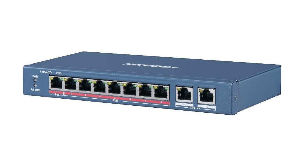
Product IntroductionDS-3E0106P-E/M series and DS-3E0310P-E/M series switches are layer 2 Hi-PoE switches, providing advanced PoE power supply technology on the basis of high-performance access to ensure stable data upload. The switches support long-range functions.
Packing List
| DS-3E0106P-E/M Series | DS-3E0310P-E/M Series | |
| Switch | × 1 | × 1 |
| Power Adapter | × 1 | × 1 |
| AC Power Cord | × 1 | × 1 |
| Quick Start Guide | × 1 | × 1 |
AppearanceDifferent models of devices may have different appearances. The following pictures are only for illustration.
Front Panel
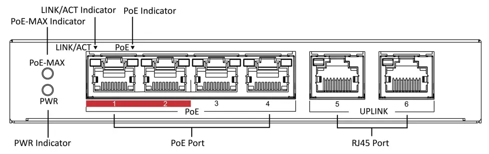
Figure 1-1 DS-3E0106P-E/M
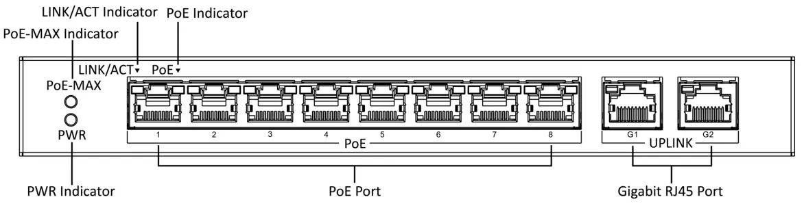
Figure 1-2 DS-3E0310P-E/M
Rear Panel
 Figure 1-3 DS-3E0106P-E/M
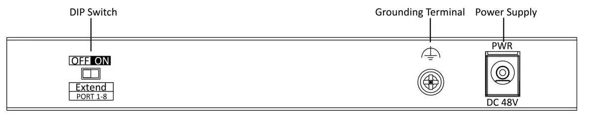 Figure 1-4 DS-3E0310P-E/M
Port/Indicator Description
| Indicator/Port | Description |
| PoE-MAX Indicator | • Solid /Flashing: The output power of the switch will reach the upper limit. The power supply may be abnormal if more devices are connected.• Unlit: The switch provides a power supply to PD normally. |
| PWR Indicator | • Solid: The switch is powered on normally.• Unlit: No power supply connected or power supply is abnormal. |
| LINK/ACT Indicator | • Solid: The port is connected.• Flashing: The port is transmitting data.• Unlit: The port is disconnected or the connection is abnormal. |
| PoE Indicator | • Solid: The switch provides power supply to PD normally.• Unlit: The switch is disconnected to PD, or provides a power supply to PD abnormally. |
| PoE Port | Used for other PD devices connected via network cables. |
| (Gigabit) RJ45 Port | Used for devices connected via network cables. |
| Grounding Terminal | Used for connecting to the grounding cable to protect the switch from lightning. |
| Power Supply | Use the attached power cord to connect the switch to the socket. |
|
DIP Switch |
Support extend mode: Ports 1 to 4 of DS-3E0106P- E/M and ports 1 to 8 of DS-3E0310P-E/M support network transmission of up to 300 meters. |
Installation
Please select the appropriate installation method according to the actual needs.Before You Start
- Keep the room well-ventilated.
- Keep at least a 10 cm distance around the device for heat dissipation.
Desk-Mounted InstallationPlace the device on the desk.
Wall-Mounted InstallationSteps
- Check the distance between the two hanging holes on the rear cover of the device.
- Insert two M4 screws into the wall.
 Note• Please prepare two M4 screws.• Ensure that the distance between the two screws equals that between the two hanging holes.• Set aside at least 4 mm screws outside the wall.
 - Align the hanging holes with screws, and hang the device on the screws.

Grounding
Connecting the Grounding CableGrounding is used to quickly release overvoltage and overcurrent induced by lightning for switches, and to protect personal safety. Select the appropriate grounding method according to your needs.
With Grounding BarIf a grounding bar is available at the installation site, follow the steps below.
Steps
- Connect one end of the grounding cable to the binding post on the grounding bar.
- Connect the other end of the grounding cable to the grounding terminal of the device and fix the screw.
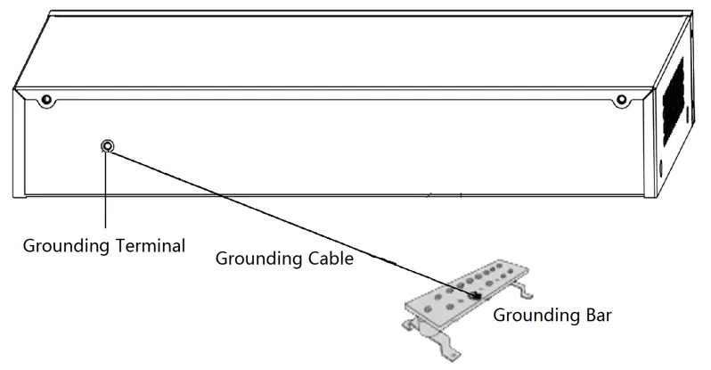
Figure 3-1 Grounding with Grounding Bar
Without Grounding BarIf there is no grounding bar but the earth is nearby and the grounding body is allowed to be buried, follow the steps below.Steps
- Bury an angle steel or steel pipe (≥ 0.5 m) into the mud land.
- Weld one end of the grounding cable to the angle steel or steel pipe and embalm the welding point via electroplating or coating.
- Connect the other end of the grounding cable to the grounding terminal.
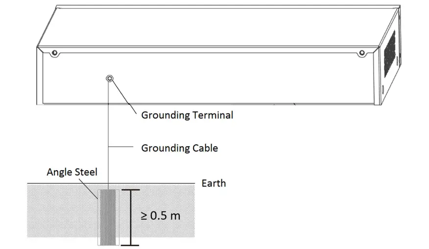
Figure 3-2 Grounding with Angle Steel
Connecting RJ45 PortUse a network cable to connect the device to the RJ45 port of a peer device such as network camera, NVR, switch, etc.
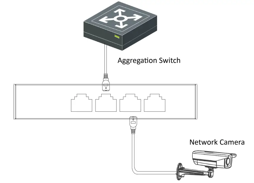
Figure 3-3 RJ45 Port Connection
Powering on the Device
Please use the attached power cord in the package to power on the device.Before powering your switch, make sure that:
- The operating power supply is compliant with rated input standards.
- Port cables and grounding cables are correctly connected.
- If there is outdoor cabling, connect a lightning rod and lightning arrester to the cable.
 report this ad
CautionPoE power supply line and strong wire cannot be wired together, otherwise, PD equipment or switch ports will be burnt.
References
[xyz-ips snippet=”download-snippet”]