![]() EKI-K41B44W Wi-Fi KitNVR: DS-7104NI-K1/W/M NVR Cameras: DS-2CV1041G1-IDWQuick Start Guide
EKI-K41B44W Wi-Fi KitNVR: DS-7104NI-K1/W/M NVR Cameras: DS-2CV1041G1-IDWQuick Start Guide
© 2020 Hangzhou Hikvision Digital Technology Co., Ltd. All rights reserved.This Manual is the property of Hangzhou Hikvision Digital Technology Co., Ltd. or its affiliates (hereinafter referred to as “Hikvision”), and it cannot be reproduced, changed, translated, or distributed, partially or wholly, by any means, without the prior written permission of Hikvision. Unless otherwise expressly stated herein, Hikvision does not make any warranties, guarantees, or representations, express or implied, regarding the Manual, any information contained herein.
About this Manual,The Manual includes instructions for using and managing the Product. Pictures, charts, images, and all other information hereinafter are for description and explanation only. The information contained in the Manual is subject to change, without notice, due to firmware updates or other reasons. Please find the latest version of this Manual at the Hikvision Website (http://www.hikvision.com/).
Please use this Manual with the guidance and assistance of professionals trained in supporting the Product.
Trademarks Acknowledgement![]() and other Hikvision trademarks and logos are the properties of Hikvision in various jurisdictions.
and other Hikvision trademarks and logos are the properties of Hikvision in various jurisdictions.
Other trademarks and logos mentioned are the properties of their respective owners.
LEGAL DISCLAIMERTO THE MAXIMUM EXTENT PERMITTED BY APPLICABLE LAW, THIS MANUAL AND THE PRODUCT DESCRIBED, WITH ITS HARDWARE, SOFTWARE, AND FIRMWARE, ARE PROVIDED “AS IS” AND “WITH ALL FAULTS AND ERRORS.” HIKVISION MAKES NO WARRANTIES, EXPRESS OR IMPLIED, INCLUDING WITHOUT LIMITATION, MERCHANTABILITY, SATISFACTORY QUALITY, OR FITNESS FOR A PARTICULAR PURPOSE. THE USE OF THE PRODUCT BY YOU IS AT YOUR OWN RISK. IN NO EVENT WILL HIKVISION BE LIABLE TO YOU FOR ANY SPECIAL, CONSEQUENTIAL, INCIDENTAL, OR INDIRECT DAMAGES, INCLUDING, AMONG OTHERS, DAMAGES FOR LOSS OF BUSINESS PROFITS, BUSINESS INTERRUPTION, OR LOSS OF DATA, CORRUPTION OF SYSTEMS, OR LOSS OF DOCUMENTATION, WHETHER BASED ON BREACH OF CONTRACT, TORT (INCLUDING NEGLIGENCE), PRODUCT LIABILITY, OR OTHERWISE, IN CONNECTION WITH THE USE OF THE PRODUCT, EVEN IF HIKVISION HAS BEEN ADVISED OF THE POSSIBILITY OF SUCH DAMAGES OR LOSS.
YOU ACKNOWLEDGE THAT THE NATURE OF THE INTERNET PROVIDES FOR INHERENT SECURITY RISKS, AND HIKVISION SHALL NOT TAKE ANY RESPONSIBILITIES FOR ABNORMAL OPERATION, PRIVACY LEAKAGE, OR OTHER DAMAGES RESULTING FROM CYBER-ATTACK, HACKER ATTACK, VIRUS INFECTION, OR OTHER INTERNET SECURITY RISKS; HOWEVER, HIKVISION WILL PROVIDE TIMELY TECHNICAL SUPPORT IF REQUIRED.
YOU AGREE TO USE THIS PRODUCT IN COMPLIANCE WITH ALL APPLICABLE LAWS, AND YOU ARE SOLELY RESPONSIBLE FOR ENSURING THAT YOUR USE CONFORMS TO THE APPLICABLE LAW. ESPECIALLY, YOU ARE RESPONSIBLE, FOR USING THIS PRODUCT IN A MANNER THAT DOES NOT INFRINGE ON THE RIGHTS OF THIRD PARTIES, INCLUDING WITHOUT LIMITATION, RIGHTS OF PUBLICITY, INTELLECTUAL PROPERTY RIGHTS, OR DATA PROTECTION, AND OTHER PRIVACY RIGHTS. YOU SHALL NOT USE THIS PRODUCT FOR ANY PROHIBITED END-USES, INCLUDING THE DEVELOPMENT OR PRODUCTION OF WEAPONS OF MASS DESTRUCTION, THE DEVELOPMENT OR PRODUCTION OF CHEMICAL OR BIOLOGICAL WEAPONS, ANY ACTIVITIES IN THE CONTEXT RELATED TO ANY NUCLEAR EXPLOSIVE OR UNSAFE NUCLEAR FUEL-CYCLE, OR IN SUPPORT OF HUMAN RIGHTS ABUSES.
IN THE EVENT OF ANY CONFLICTS BETWEEN THIS MANUAL AND THE APPLICABLE LAW, THE LATTER PREVAILS.
Regulatory Information
FCC InformationPlease take attention that changes or modifications not expressly approved by the party responsible for compliance could void the user’s authority to operate the equipment.
FCC Compliance:This equipment has been tested and found to comply with the limits for a Class B digital device, pursuant to part 15 of the FCC Rules. These limits are designed to provide reasonable protection against harmful interference in a residential installation. This equipment generates, uses and can radiate radio frequency energy and, if not installed and used in accordance with the instructions, may cause harmful interference to radio communications. However, there is no guarantee that interference will not occur in a particular installation. If this equipment does cause harmful interference to radio or television reception, which can be determined by turning the equipment off and on, the user is encouraged to try to correct the interference by one or more of the following measures:
- Reorient or relocate the receiving antenna.
- Increase the separation between the equipment and receiver.
- Connect the equipment into an outlet on a circuit different from that to which the receiver is connected.
- Consult the dealer or an experienced radio/TV technician for help. This equipment should be installed and operated with a minimum distance of 20 cm between the radiator and your body.
FCC ConditionsThis device complies with part 15 of the FCC Rules. Operation is subject to the following two conditions:
- This device may not cause harmful interference.
- This device must accept any interference received, including interference that may cause undesired operation
EU Conformity Statement
This product and, if applicable, the supplied accessories too are marked with “CE” and comply therefore with the applicable harmonized European standards listed under the EMC Directive 2014/30/EU, the RoHS Directive 2011/65/EU, and the RE Directive 2014/53/EU.
2012/19/EU (WEEE Directive): Products marked with this symbol cannot be disposed of as unsorted municipal waste in the European Union. For proper recycling, return this product to your local supplier upon the purchase of equivalent new equipment, or dispose of it at designated collection points. For more information, see www.recyclethis.info.
2006/66/EC (Battery Directive): This product contains a battery that cannot be disposed of as unsorted municipal waste in the European Union. See the product documentation for specific battery information. The battery is marked with this symbol, which may include lettering to indicate cadmium (Cd), lead (Pb), or mercury (Hg). For proper recycling, return the battery to your supplier or to a designated collection point. For more information, see www.recyclethis.info.
Industry Canada ICES-003 ComplianceThis device meets the CAN ICES-3 (B)/NMB-3(B) standards requirements.
This device complies with Industry Canada license-exempt RSS standard(s). Operation is subject to the following two conditions:
- This device may not cause interference, and
- This device must accept any interference, including interference that may cause undesired operation of the device.
Under Industry Canada regulations, this radio transmitter may only operate using an antenna of a type and maximum (or lesser) gain approved for the transmitter by Industry Canada. To reduce potential radio interference to other users, the antenna type and its gain should be so chosen that the equivalent isotropically radiated power (e.i.r.p.) is not more than that necessary for successful communication.
This equipment should be installed and operated with a minimum distance of 20 cm between the radiator and your body.
Safety Instruction
These instructions are intended to ensure that users can use the product correctly to avoid danger or property loss.
The precaution measure is divided into “Warnings” and “Cautions”
Warnings: Serious injury or death may occur if any of the warnings are neglected.Cautions: Injury or equipment damage may occur if any of the cautions are neglected.
|
|
|
| Follow these safeguards to prevent serious injury or death. | Follow these precautions to prevent potential injury or material damage. |
![]() Warnings
Warnings
For Network Camera:
- Proper configuration of all passwords and other security settings is the responsibility of the installer and/or end-user.
- In the use of the product, you must be in strict compliance with the electrical safety regulations of the nation and region. Please refer to technical specifications for detailed information.
- The power source should meet limited power source or PS2 requirements according to IEC 60950-1 or IEC 62368-1 standard.
- Do not connect several devices to one power adapter as adapter overload may cause overheating or a fire hazard.
- Please make sure that the plug is firmly connected to the power socket. When the product is mounted on a wall or ceiling, the device shall be firmly fixed.
- If smoke, odor, or noise rise from the device, turn off the power at once, unplug the power cable, and then contact the service center.
For NVR Device:
- Proper configuration of all passwords and other security settings is the responsibility of the installer and/or end-user.
- In the use of the product, you must be in strict compliance with the electrical safety regulations of the nation and region. Please refer to technical specifications for detailed information.
- The power source should meet limited power source or PS2 requirements according to IEC 60950-1 or IEC 62368-1 standard.
- Do not connect several devices to one power adapter as adapter overload may cause overheating or a fire hazard.
- Please make sure that the plug is firmly connected to the power socket.
- If smoke, odor, or noise rise from the device, turn off the power at once, unplug the power cable, and then contact the service center.
- If the PoE ports of the device do not comply with Limited Power Source, the additional equipment connected to PoE ports shall have a fire enclosure.
- The USB interface of the /P devices can be connected with the mouse and USB flash disk storage device only.
![]() CautionsFor Network Camera:
CautionsFor Network Camera:
 CAUTION: Hot parts! Burned fingers when handling the parts.Wait one-half hour after switching off before handling parts. This sticker is to indicate that the marked item can be hot and should not be touched without taking care. For device with this sticker, this device is intended for installation in a restricted access location, access can only be gained by service persons or by users who have been instructed about the reasons for the restrictions applied to the location and about any precautions that shall be taken.
- Make sure the power supply voltage is correct before using the camera.
- Do not drop the camera or subject it to physical shock.
- Do not touch sensor modules with fingers. If cleaning is necessary, use clean cloth with a bit of ethanol and wipe it gently. If the camera will not be used for an extended period, please replace the lens cap to protect the sensor from dirt.
- Do not aim the camera at the sun or extra bright places. Blooming or smearing may occur otherwise (which is not a malfunction), and affect the endurance of the sensor at the same time.
- The sensor may be burned out by a laser beam, so when any laser equipment is in use, make sure that the surface of the sensor will not be exposed to the laser beam.
- The operating temperature shall be -30°C to +60°C (-22° to +140° F). Do not place the camera in extremely hot, cold, dusty, or damp locations, and do not expose it to high electromagnetic radiation.
- To avoid heat accumulation, good ventilation is required for the operating environment.
- Keep the camera away from the liquid while in use.
- While in delivery, the camera shall be packed in its original packing, or packing of the same texture.
- Regular part replacement: a few parts (e.g. electrolytic capacitor) of the equipment shall be replaced regularly according to their average enduring time. The average time varies because of differences between the operating environment and using history, so regular checking is recommended for all the users. Please contact with your dealer for more details.
- This equipment is not suitable for use in locations where children are likely to be present.
- CAUTION: Risk of explosion if the battery is replaced by an incorrect type. Dispose of used batteries according to the instructionsATTENTION: IL Y A RISQUE D’EXPLOSION SI LA BATTERIE EST REMPLACÉE PAR UNE BATTERIE DE TYPE INCORRECT. METTRE AU REBUT LES BATTERIES USAGÉES CONFORMÉMENT AUX INSTRUCTIONS
- Improper replacement of the battery with an incorrect type may defeat a safeguard (for example, in the case of some lithium battery types).
- Do not dispose of the battery into fire or a hot oven, or mechanically crush or cut the battery, which may result in an explosion.
- Do not leave the battery in an extremely high temperature surrounding environment, which may result in an explosion or the leakage of flammable liquid or gas.
- Do not subject the battery to extremely low air pressure, which may result in an explosion or the leakage of flammable liquid or gas.
- If the product does not work properly, please contact your dealer or the nearest service center. Never attempt to disassemble the camera yourself. (We shall not assume any responsibility for problems caused by unauthorized repair or maintenance.)
 CAUTION: Hot parts! Burned fingers when handling the parts.Wait one-half hour after switching off before handling parts. This sticker is to indicate that the marked item can be hot and should not be touched without taking care. For device with this sticker, this device is intended for installation in a restricted access location, access can only be gained by service persons or by users who have been instructed about the reasons for the restrictions applied to the location and about any precautions that shall be taken.
For NVR Device:
Before connecting and operating your device, please be advised of the following tips:
- Ensure the unit is installed in a well-ventilated, dust-free environment.
- The unit is designed for indoor use only.
- Keep all liquids away from the device.
- Ensure environmental conditions meet factory specifications.
- Ensure the unit is properly secured to a rack or shelf. Major shocks or jolts to the unit as a result of dropping it may cause damage to the sensitive electronics within the unit.
- Use the device in conjunction with a UPS if possible.
- Power down the unit before connecting and disconnecting accessories and peripherals.
- A factory-recommended HDD should be used for this device.
- Improper use or replacement of the battery may result in a hazard of explosion. Replace with the same or equivalent type only. Dispose of used batteries according to the instructions provided by the battery manufacturer.
NVR Power Supply InstructionsUse only power supplies listed in the user instructions.
| Standard | Power Supply Models | Manufacturer |
| European | MSA-C2000IC12.0- 24P-DE | MOSO POWER SUPPLY TECHNOLOGY CO., LTD |
| ADS-26FSG-12 12024EPG | SHENZHEN HONOR ELECTRONIC CO., LTD | |
| British | MSA-C2000IC12.0- 24P-GB | MOSO POWER SUPPLY TECHNOLOGY CO., LTD |
| ADS-26FSG-12 1202LIEPB | SHENZHEN HONOR ELECTRONIC CO., LTD | |
| The U.S. | 101700626 Adapter MSA-C20001C12.0-24P-US | US-PLUG, AC100-240V, 12V 2A, 24W, 02.1×5.5×10 |
Introduction
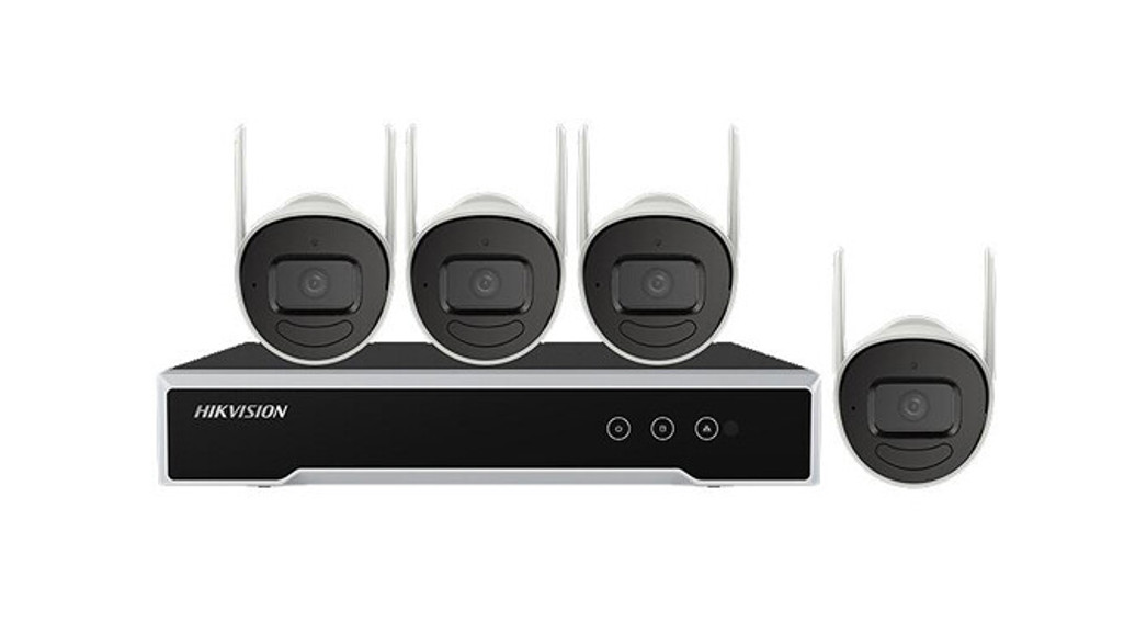
1.1 ApplicationThe Wi-Fi kit includes four network cameras and an NVR device. The NVR works as a wireless network router, and the camera connects to the NVR’s Wi-Fi automatically after the camera is powered on.
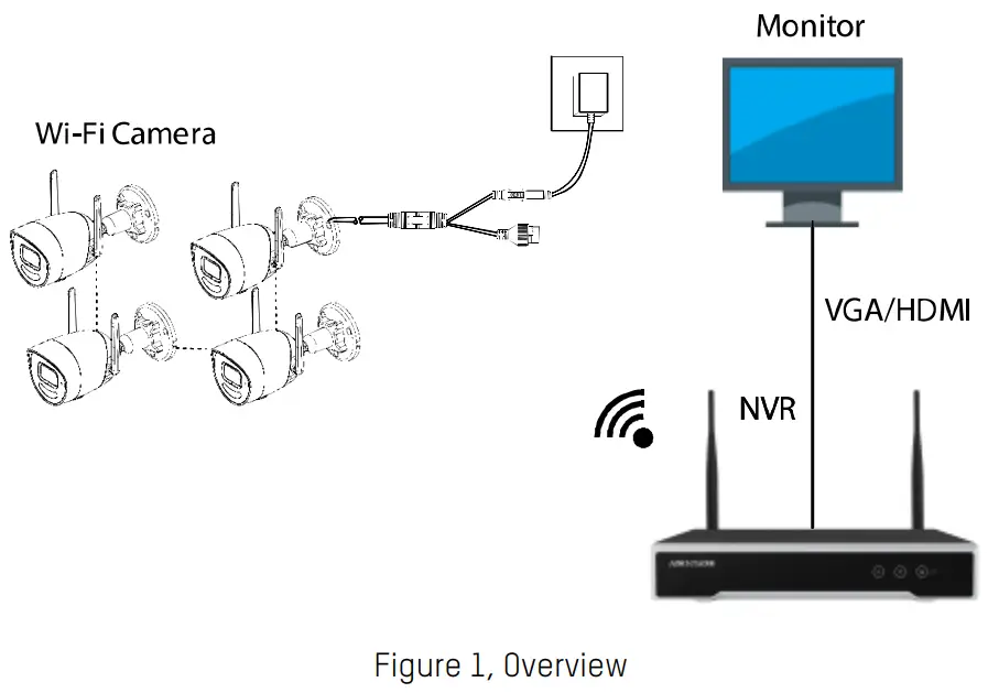
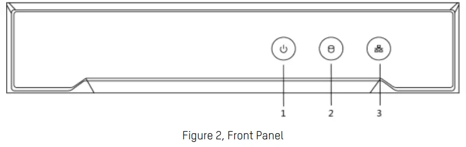
 NOTE: To access the NVR via the Internet, connect the NVR to the router.1.2 NVR Appearance1.2.1 Front Panel
|
No. |
Icon |
Description |
| 1 | The indicator turns red when NVR is powered up. | |
| 2 | Indicator lights in red when there is data transmission. | |
| 3 | The indicator blinks blue when the network connection is functioning properly. |
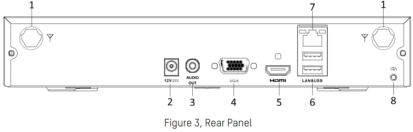
1.2.2 Rear Panel
Description
| No. | Icon |
Description |
|
1 |
Wi-Fi Antenna | Wi-Fi antenna interface |
| 2 | Power supply | 12 VDC power supply |
| 3 | Audio out | One audio output |
| Li | VGA | VGA interface |
| 5 | HDMI | HDMI video output connector |
| 6 |
USB |
Two USB 2.0 interface |
| 7 | LAN | One RJ-45 10M/100M self-adaptive Ethernet interface |
| 8 | Ground | Ground (needs to be connected when the device starts up) |
1.3 Camera Appearance

Description
| No. | Description |
| 1 | Bracket |
| 2 | Back Cover |
| 3 | Main Body |
| 4 | Front Cover |
| 5 | IR LED Cover |
| 6 | Status Indicator |
| 7 | Lens |
| 8 | Microphone |
| 9 | IR LED |
| 10 | Power Interface |
| 11 | Network Interface |
| 12 | RESET Button |
| 13 | Memory Card Slot |
| 14 | Antenna |
NOTE: Hold RESET about 10s when the camera is powering on or rebooting to restore the default settings, including the user name, password, IP address, port no., etc.
NVR Installation
2.1 Precautions
During the installation of the NVR:
- Use brackets for rack mounting
- Ensure ample room for audio and video cables
- When routing cables, ensure that the bend radius of the cables is no less than five times than its diameter.
- Connect the alarm cable.
- Allow at least 2 cm (~0.75-inch) of space between racks mounted devices.
- Ensure the NVR is grounded.
- The environmental temperature should be within the range of -10° to +55° C, +14° to +131° F.
- Environmental humidity should be within the range of 10% to 90%.
2.2 Hard Disk Drive Installation
Before You Start
- If the NVR has been installed with hard disks, skip this section.
- Disconnect the power from the NVR before installing a hard disk drive (HDD). Use only a factory-recommended HDD for this installation.
- Tools Required: Screwdriver.
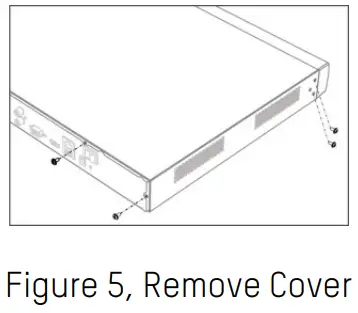
- Remove the cover from the device by unfastening the screws on the panels.
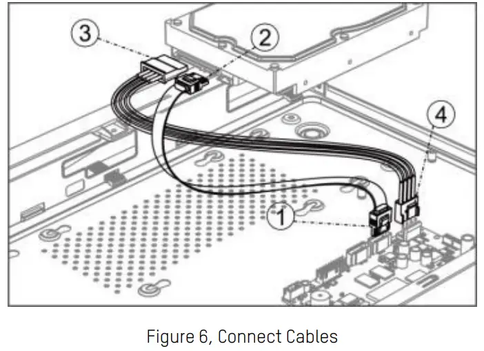
- Connect the data cable and power cable.a) Connect one end of the data cable to the device motherboard.b) Connect the other end of the data cable to the HDD.c) Connect one end of the power cable to the HDD.d) Connect the other end of the power cable to the device motherboard.
- Set the device up, match HDD screw threads with the reserved holes on the device bottom, and fix HDD with screws.
- (Optional) Repeat the steps above to install other HDDs.
- Reinstall the device cover, and fasten screws.
Camera Installation
Before You Start
- Make sure the device in the package is in good condition and all the assembly parts are included.
- The standard power supply is 12 VDC. Make sure your power supply matches your camera.
- Make sure all the related equipment is powered off during the installation.
- Check the specification of the products for the installation environment.
- Make sure that the wall is strong enough to withstand four times the weight of the camera and the bracket.
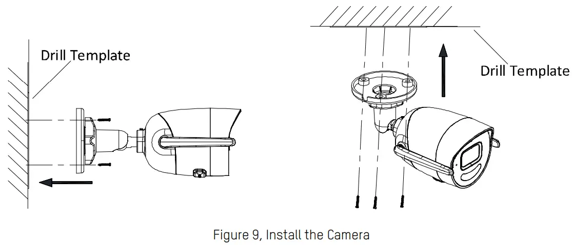
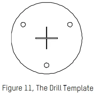
- Paste the drill template on the wall or ceiling, and drill holes according to the marked holes on the drill template.
-
If you need to route cables through the wall or ceiling, drill a cable hole according to the drill template. Skip this step if you want to route the cables on the surface of the wall or ceiling.
-
Route the camera cables.
-
Install the camera to the wall or ceiling with screws.NOTE: The supplied screw package contains both self-tapping screws and expansion bolts.If the ceiling is concrete, expansion bolts are required to fix the camera. If the ceiling is wood, self-tapping screws are required.
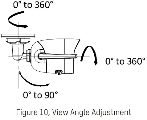
- Adjust the view angle of the camera.3-axis (pan/tilt/rotation) adjusting allows adjustment for optimum camera rotation and placement.a) Loosen the 3-axis adjusting nut.b) Adjust the panning, tilting. and rotation position of the camera. The panning adjusting range is from 0° to 360°, tilting range is from 0° to 90° and rotation range is 0° to 360°.c) Tighten the adjusting nut
3.2 Mounting with a Junction Box
Before You StartBoth wall mounting and ceiling mounting are suitable for the bullet camera. Wall mounting will be taken as an example in this section.
Take the wall mounting steps as a reference for ceiling mounting.You need to purchase a junction box first.
- Paste the drill template (supplied) to the desired mounting position on the wall.
- Drill the screw holes and the cable hole (optional) in the wall according to the drill template.NOTE: Drill the cable hole, if adopting a ceiling outlet to route the cable.
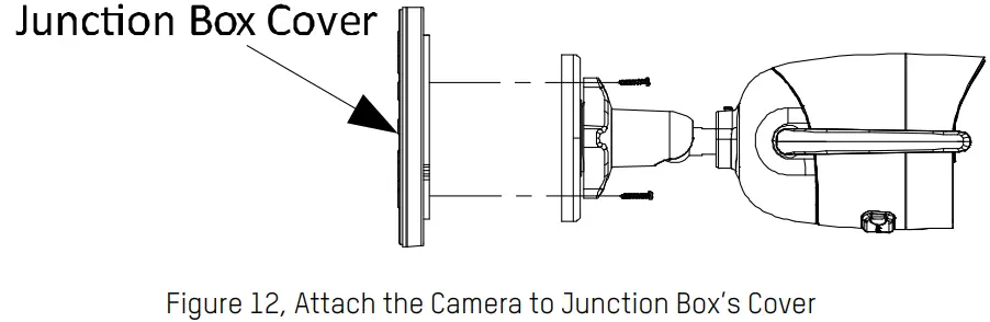
- Disassemble the junction box, and align the camera screw holes with those on the junction box’s cover.
- Fix the camera on the junction box’s cover with screws.
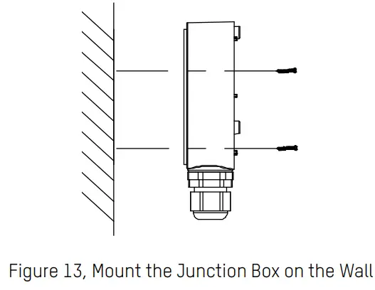
- Secure the junction box’s body to the wall with three supplied screws.
- Route the cables through the cable hole.
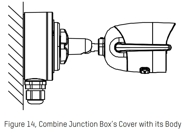
- Combine the junction box cover with its body with three screws on the junction box‘s cover.
- Repeat steps 5 of 3.1 Ceiling Mounting to complete the installation.
3.3 Waterproof Measures
If the camera is installed outdoors, use the waterproof accessory or tape to waterproof the cables.Otherwise, the cables might get wet or a short circuit occurs.
3.3.1 Install Network Cable Waterproof Jacket
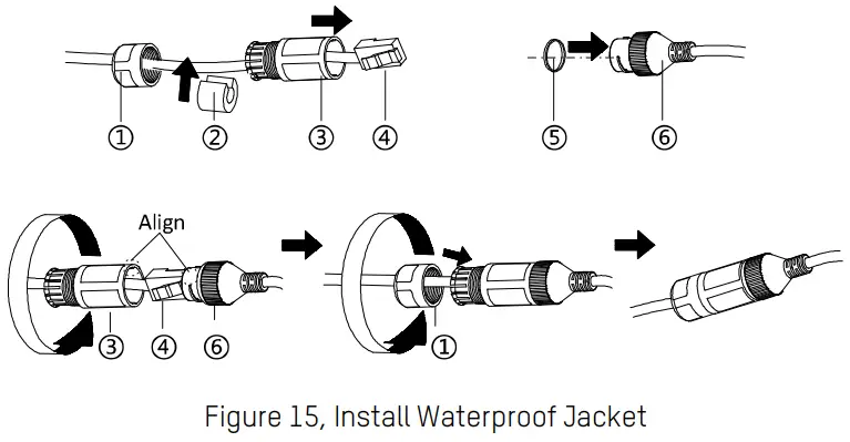
- Feed the network cable through ① and ③ in order.
- Fix ② on the network cable between ① and ③.
- Place ⑤ onto the end of ⑥, and plug the RJ-45 male connector into the RJ-45 female connector.
- Screw ③ to ⑥ clockwise.
- Push ② into ③.
- Secure ① with the ③ in the clockwise direction.
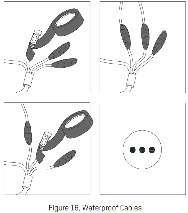
3.3.2 Waterproof Other CablesAfter routing and connecting the cables, use waterproof tape to wrap up the cables. Connected cables and spare cables both should be wrapped as the figures below.
4.1 Startup and Shutdown
To start your NVR:
- Check the power supply is plugged into an electrical outlet. It is HIGHLY recommended that an Uninterruptible Power Supply (UPS) be used in conjunction with the device. The Power button on the front panel should be red, indicating the device is receiving power.
- Plug the power adapter into supply power to the NVR, there is no on/off switch. The Power LED should turn blue. The unit will start.After the device starts up, the wizard will guide you through the initial settings, including modifying password, date and time settings, network settings, HDD initializing, and recording.
To shut down the NVR:
- Enter the Shutdown menu. Go to Menu > Shutdown.
- Select Shutdown.
- Click Yes.
4.2 Activate Your NVR
Purpose
For first-time access, you need to activate the NVR by setting an admin password. No operation is allowed before activation. You can also activate the NVR via Web Browser, SADP or client software.
- Input the same password in the text field of Create New Password and Confirm New Password. STRONG PASSWORD RECOMMENDED − We highly recommend that you create a strong password of your own choosing (using a minimum of eight characters, including at least three of the following categories: upper case letters, lower case letters, numbers, and special characters) in order to increase the security of your product. We also recommend that you reset your password regularly. Especially in high-security systems, resetting the password monthly or weekly can better protect your product.Proper configuration of all passwords and other security settings is the responsibility of the installer and/or end-user.
- Enter IP Camera Activation Password to set the IP camera activation password.
- Select Area/Country.
- Click OK.
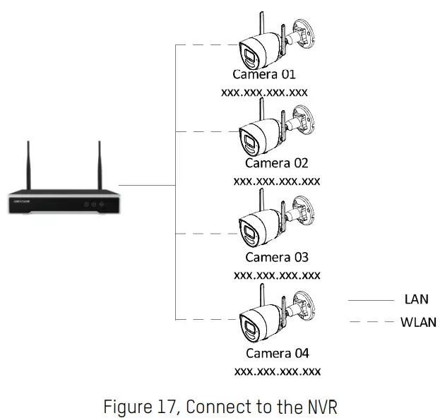
4.3 Use the Setup WizardThe Setup Wizard can guide you to configure the system resolution, system date/time, HDD initialization, IP camera management, etc.4.4 Add IP Cameras4.4.1 Wi-Fi Kit CamerasThe supplied Wi-Fi kit cameras can connect to the NVR automatically after it is powered on.
- Connect the NVR to a display.
- Connect cameras 01, 02, 03, and 04 to the NVR. The cameras connect to the NVR’s Wi-Fi automatically.NOTE: Make sure the distance between cameras 01, 02, 03, 04, and the NVR is no more than 49 ft (15 m).
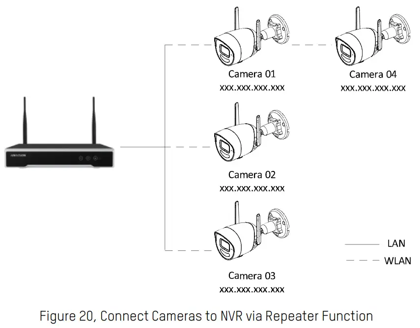
- (Optional) If you want to install a camera beyond the NVR’s Wi-Fi distance, you can enable the NVR’s repeater function. The repeater function allows a camera with the repeater function to serve as a range extender for another camera beyond the reach of the NVR’s Wi-Fi.A Wi-Fi camera beyond the NVR’s Wi-Fi range can automatically connect to the NVR by using a nearby Wi-Fi camera as a repeater.
- Right-click the screen and select Menu > Camera.
- Click the Enable Repeater button 1 to enable the NVR’s repeater function.Make sure the distance between each camera and the NVR is no more than 49 ft (15m), the NVR’s maximum Wi-Fi range. Any camera beyond this range can use an in-range camera’s repeater function to communicate with the NVR. The camera’s repeater function can extend the range to another camera an additional 49 ft (15 m). The Wi-Fi range will vary by local conditions (e.g., number of walls, materials, electrical interference, etc.).
- Install the camera that is to be used as a repeater at the desired position within the NVR’s Wi-Fi range, and power it on.
- Click the in-range repeater camera’s Repeater switch 3 so that it toggles to the right (it will display a green background) to enable its repeater function.
- Install the camera at the desired position beyond the NVR’s normal range and power it on. It will then connect to the NVR through the repeater camera.
NOTE:Only one camera can use anyone camera’s repeater function.The repeater function cannot be daisy-chained.

NOTE: To disable a camera’s repeater function, click the Repeater switch 3 so that it toggles to the left (the background will no longer be green).To disable the NVR’s repeater function, click the Disable Repeater button 2.
4.4.2 Other Cameras
For cameras not included in the kit, choose one of the following methods to add the cameras.
Auto Connection
- Power the camera up and hold the RESET button for 10 seconds to restore the camera to defaults.NOTE: Make sure the camera is not activated before the installation.
- Right-click the screen and select Wi-Fi Match. The camera will connect to the NVR within 120 s.
Manual Connection
- Click to select an idle window in the live view mode.
- Click
+in the center of the window. - Select the detected IP camera and click Add to add it directly.
- Go to Menu > Configuration > Wi-Fi.
- Set wireless network parameters, including Network Bridging, SSID, Security Mode, and Key.
- Access the Web of the camera.
- Go to Configuration > Network > Advanced Settings > Wi-Fi to set the Wi-Fi parameters.NOTE: For detailed information, see the Network Camera User Manual.
The Hik-Connect mobile client can generally manage various kinds of devices. With the client, you can remotely control NVRs, DVRs, network cameras, etc.
- Get and install the Hik-Connect application in the following ways.• Visit https://appstore.hikvision.com to download the application according to your mobile phone system.• Visit the official site of our company. Then go to Support > Tools > Hikvision App Store.• Scan the QR code below to download the application.https://www.hik-connect.com/views/qrcode/hc/index.htmlNOTE: If errors such as “Unknown app” occur during the installation, solve the problem in two ways:• Visit https://appstore.hikvision.com/static/help/index.html to refer to the troubleshooting.• Visit https://appstore.hikvision.com/ and click Installation Help at the upper right corner of the interface to refer to the troubleshooting.
- Launch the app and register for a Hik-Connect user account.
- Log in Hik-Connect app after registration.
- Use a network cable to connect the NVR with a router.
- In the Hik-Connect app, tap “+” on the upper-right corner, then scan the NVR QR code to add the NVR.
- After the addition, you can get the live view and playback the videos in the app. NOTE For detailed information, refer to the Hik-Connect User Manual.

 report this ad
QSG EKI-K41B44W Kit 110520NA
References
[xyz-ips snippet=”download-snippet”]