![]()
Network Indoor StationInstallation Guide
![]()
Symbol Conventions
The symbols that may be found in this document are defined as follows.
| Symbol | Description |
| Indicates a hazardous situation which, if not avoided, will or could result in death or serious injury. | |
| Indicates a potentially hazardous situation which, if not avoided, could result in equipment damage, data loss, performance degradation, or unexpected results. | |
| Provides additional information to emphasize or supplement important points of the main text. |
About this Manual
Get the manual and related software from or the official website (http://www.hikvision.com).
| Product | Model |
| Network Indoor Station | DS-KH6320-WTE1, DS-KH6320-TE1 |
Scan the QR code to get the configuration guide for detailed information. http://enpinfodata.hikvision.com/analysisQR/showQR/72e68fa8Scan the QR code to get the operation guide for detailed information.
 http://enpinfodata.hikvision.com/analysisQR/showQR/571af60f
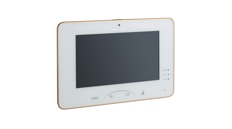
Appearance
Front Panel
Figure 2-1 Front Panel Table 2-1 Description
| No. | Description |
| 1 | Screen |
| 2 | Microphone |
Rear Panel
Figure 2-2 Rear Panel Table 2-2 Description
| No. | Description |
| 3 | Network Interface |
| 4 | Loudspeaker |
| 5 | TF Card Slot |
| 6 | Alarm Terminal |
| 7 | Reserved |
| 8 | Power Terminal |
Wiring Description
There are 20 pins in the terminal on the rear panel of the indoor station: 2 RS-485 pins, 5 reserved pins, 4 relay output pins, 8 alarm input pins, and 1 GND pin.![]() NoteThere are 20 pins in the terminal on the rear panel of the DS-KH6320-TE1: 11 reserved pins, 8 alarm input pins, and 1 GND pin. Please refer to the specific model.
NoteThere are 20 pins in the terminal on the rear panel of the DS-KH6320-TE1: 11 reserved pins, 8 alarm input pins, and 1 GND pin. Please refer to the specific model.
Figure 3-1 Wiring Description (Alarm Input Device)
The internal circuit structure of the relay output is shown as below.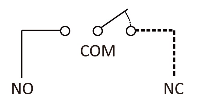
Figure 3-2 Relay Output Internal Circuit Structure
Installation
It supports wall mounting. There are two installation modes.
Wall Mounting Plate
The wall mounting plate and the junction box are required to install the indoor station onto the wall. The dimension of junction box should be 75 mm (width) × 75 mm (length) × 50 mm (depth). The dimension of wall mounting plate is shown .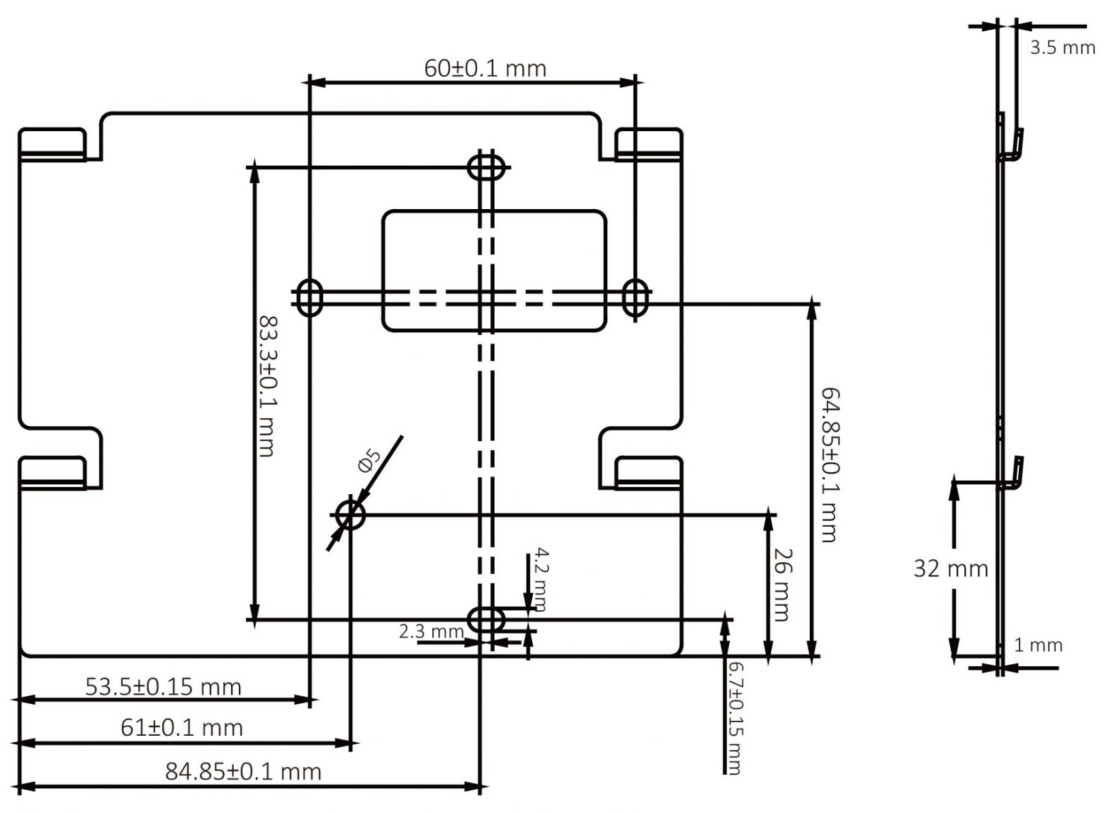
Figure 4-1 Wall Mounting Plate
Wall Mounting with Junction Box
Before You Start![]() Note• Make sure the device in the package is in good condition and all the assembly parts are included.• The power supply the indoor station supports is 12 VDC. Please make sure your power supply matches your indoor station.• Make sure all the related equipment is power-off during the installation.• Check the product specification for the installation environment.Steps1. Chisel a hole in the wall. The size of the hole should be 76 mm (width) × 76 mm (length) × 50 mm (depth).2. Insert the junction box to the hole chiseled on the wall.3. Fix the wall mounting plate to the junction box with 2 screws.4. Hook the indoor station to the wall mounting plate tightly by inserting the plate hooks into the slots on the rear panel of the indoor station, during which the lock catch will be locked automatically.
Note• Make sure the device in the package is in good condition and all the assembly parts are included.• The power supply the indoor station supports is 12 VDC. Please make sure your power supply matches your indoor station.• Make sure all the related equipment is power-off during the installation.• Check the product specification for the installation environment.Steps1. Chisel a hole in the wall. The size of the hole should be 76 mm (width) × 76 mm (length) × 50 mm (depth).2. Insert the junction box to the hole chiseled on the wall.3. Fix the wall mounting plate to the junction box with 2 screws.4. Hook the indoor station to the wall mounting plate tightly by inserting the plate hooks into the slots on the rear panel of the indoor station, during which the lock catch will be locked automatically.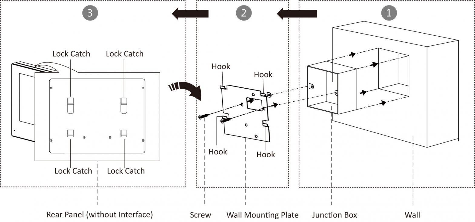
Figure 4-2 Wall Mounting with Junction Box
Mounting Indoor Station without Junction Box
Before You Start![]() Note• Make sure the device in the package is in good condition and all the assembly parts are included.• The power supply the indoor station supports is 12 VDC. Please make sure your power supply matches your indoor station.• Make sure all the related equipment is power-off during the installation.• Check the product specification for the installation environment.Steps1. Insert 2 expension tubes into the wall.2. Fix the wall mounting plate to the junction box with 2 screws.3. Hook the indoor station to the wall mounting plate tightly by inserting the plate hooks into the slots on the rear panel of the indoor station, during which the lock catch will be locked automatically.
Note• Make sure the device in the package is in good condition and all the assembly parts are included.• The power supply the indoor station supports is 12 VDC. Please make sure your power supply matches your indoor station.• Make sure all the related equipment is power-off during the installation.• Check the product specification for the installation environment.Steps1. Insert 2 expension tubes into the wall.2. Fix the wall mounting plate to the junction box with 2 screws.3. Hook the indoor station to the wall mounting plate tightly by inserting the plate hooks into the slots on the rear panel of the indoor station, during which the lock catch will be locked automatically.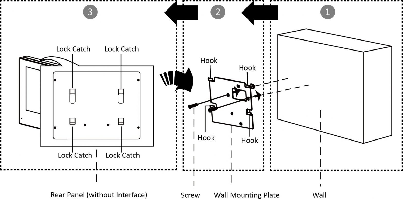
Figure 4-3 Wall Mounting without Junction Box

References
[xyz-ips snippet=”download-snippet”]