HIKVISION Network Indoor Station User Guide
Symbol Conventions
The symbols that may be found in this document are defined as follows.
| Symbol | Description |
| Indicates a hazardous situation which, if not avoided, will or could result in death or serious injury. | |
| Indicates a potentially hazardous situation which, if not avoided, could result in equipment damage, data loss, performance degradation, or unexpected results. | |
| Provides additional information to emphasize or supplement important points of the main text. |
Safety Instruction
![]() Warning
Warning
- The working temperature of the device is from -10 ºC to 55 ºC.
- All the electronic operation should be strictly compliance with the electricalsafety regulations, fire prevention regulations and other related regulations in your local region.
- Please use the power adapter, which is provided by normal company. The power consumption cannot be less than the required value.
- Do not connect several devices to one power adapter as adapter overload may cause over-heat or fire hazard.
- Please make sure that the power has been disconnected before you wire, install or dismantle the device.
- When the product is installed on wall or ceiling, the device shall be firmly fixed.
- If smoke, odors or noise rise from the device, turn off the power at once and unplug the power cable, and then please contact the service center.
- If the product does not work properly, please contact your dealer or the nearest service center. Never attempt to disassemble the device yourself. (We shall not assume any responsibility for problems caused by unauthorized repair or maintenance.)
![]() Caution
Caution
- Do not drop the device or subject it to physical shock, and do not expose it to high electromagnetism radiation. Avoid the equipment installation on vibrations surface or places subject to shock (ignorance can cause equipment damage).
- Do not place the device in extremely hot (refer to the specification of the device for the detailed operating temperature), cold, dusty or damp locations, and do not expose it to high electromagnetic radiation.
- The device cover for indoor use shall be kept from rain and moisture.
- Exposing the equipment to direct sun light, low ventilation or heat source such as heater or radiator is forbidden (ignorance can cause fire danger).
- Do not aim the device at the sun or extra bright places. A blooming or smear may occur otherwise (which is not a malfunction however), and affecting the endurance of sensor at the same time.
- Please use the provided glove when open up the device cover, avoid direct contact with the device cover, because the acidic sweat of the fingers may erode the surface coating of the device cover.
- Please use a soft and dry cloth when clean inside and outside surfaces of the device cover, do not use alkaline detergents.
- Please keep all wrappers after unpack them for future use. In case of any failure occurred, you need to return the device to the factory with the original wrapper. Transportation without the original wrapper may result in damage on the device and lead to additional costs.
- Improper use or replacement of the battery may result in hazard of explosion. Replace with the same or equivalent type only. Dispose of used batteries according to the instructions provided by the battery manufacturer.
- Input voltage should meet both the SELV and the Limited Power Source according to 60950-1 standard.
- The power supply must conform to LPS. The recommended adaptor models and manufacturers are shown as below. Use the attached adapter, and do not change the adaptor randomly.
| Model | Manufacturer | Standard |
| ADS-24S-12 1224GPCN | SHENZHEN HONOR ELECTRONIC CO.,LTD | CEE |
| G0549-240-050 | SHENZHEN GOSPELL DIGITAL TECHNOLOGY CO.,LTD | CEE |
| TS-A018-120015Ec | SHENZHEN TRANSIN TECHNOLOGIES CO., LTD | CEE |
Local Operation
Call SettingsAdd Contact
Steps:
- Tap Call
 to enter the contact list page.Figure 1-1 Contact List
 - Tap to pop up the contact adding dialog.
- Enter contact information.
- If you adopt private SIP protocol, enter the contact name and the room No.
- If you adopt standard SIP protocol, enter the contact name and the phone number of VOIP account.
- Tap OK to save the settings. Note Up to 200 contacts can be added.
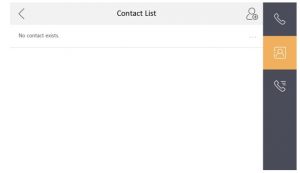 Figure 1-1 Contact List
Call Resident
Steps:
- Tap Call to enter the residents calling page.Figure 1-2 Call Resident
- Enter the calling number.
- When you adopt private SIP protocol, the calling number format should be xx-x-xxx. For example, the calling number of Community 1, Building 2, Unit 3, and Room 405 is 1-2-3-405. NoteThe community No. can be omitted.
- When you adopt standard SIP protocol, the calling number should be the phone number of VOIP account.
- When you adopt private SIP protocol, the calling number format should be xx-x-xxx. For example, the calling number of Community 1, Building 2, Unit 3, and Room 405 is 1-2-3-405.
- Tap the call button to start an audiovisual call.
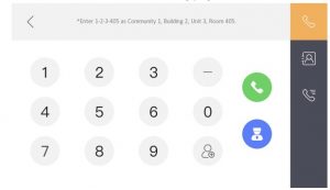 Figure 1-2 Call Resident
Call Indoor Extension/Indoor StationIf you install indoor station and indoor extensions at home, you can call the indoor extension via your indoor station, and vice versa.Enter [0-indoor extension No.]on the indoor station to start calling.Enter [0-0] to call the indoor station from the indoor extension.Receive CallThe indoor station and indoor extension can receive calls from the door station, the master station or iVMS-4200 Client. On the call from door station interface, there are 2 unlock buttons: Unlock 1, and Unlock 2. When you tap Unlock 1, the building gate will open by default, and when you tap Unlock 2, the door connected to the door station with the secure control door unit will open.Tap the capture button to capture the live view picture when speaking with the door station. And prompts “Captured” will display on the screen. Indoor extension can receive calls from the door station and the master station only.View Call LogsSteps
- Tap Call to enter the call log page.Figure 1-3 Call Logs
- Tap a piece of call logs in the list to call back. Note
- Indoor extension does not support this function.
- The indoor station saves call logs from door station, outer door station, management center and other indoor stations.
- Hold a piece of call logs to open the call logs handling menu.
- Tap Delete to delete the piece of call logs.
- Tap Clear to delete all pieces of call logs.
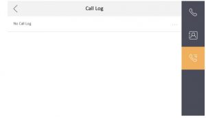 Figure 1-3 Call Logs
Live ViewOn the live view page, you can view the live video of added door station and network camera.Steps![]() Note
Note
- Make sure the network camera or door station is well-connected.
- Make sure the indoor extension and the indoor station are well-connected.
- Tap Live View to enter the live view page.Figure 1-4 Live View
- Tap to enter the live view page of door station. NoteOn the Call from Door Station page, there are 2 unlock buttons: Unlock 1, and Unlock 2. When you tap Unlock 1, the building gate will open by default. When you tap Unlock 2, the door station connected door will open.
- Tap to enter the live view page of network cameras.
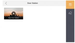 Figure 1-4 Live View
Arm/DisarmThe indoor station has four kinds of scene modes: sleeping mode, stay mode, away mode, and custom mode. You can arm or disarm your room in each scene mode manually. The selected scene mode will be displayed on the main page of the indoor station.Arm RoomSteps
- Tap to enter the scene page.Figure 1-5 Arm Settings page
- Select Stay, Away, Sleeping or Custom.
- Enter the scene password to enable the scene.
- Tap OK. NoteYou can also tap One-Push to Arm to enable the scene.
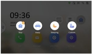 Figure 1-5 Arm Settings page
Disarm RoomSteps
- Tap One-Push to Disarm to disarm.Figure 1-6 Disarm Room
- Enter the scene password.
- Tap OK.
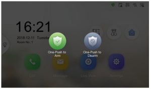 Figure 1-6 Disarm Room
Arming Mode Settings4 arming modes can be configured: stay mode, away mode, sleeping mode and custom mode.Before You StartTap Settings![]() Preference to enable Alarm.Steps
Preference to enable Alarm.Steps![]() NoteArming status page and zone settings page are hidden by default. You should enable alarm function first.
NoteArming status page and zone settings page are hidden by default. You should enable alarm function first.
- Tap Settings to enter the arming mode settings page.
- Tap Stay Mode, Away Mode, Sleeping Mode, or Custom to enter the page.Figure 1-7 Arming Mode Settings
- Arm the selected zone. Note
- Zones are configurable on the arming mode page.
- 24H alarm zone including smoke detector zone and gas detector zone will be triggered even if they are disabled.
- Arming mode settings should be configured with the settings of arming status on the user page of the device.
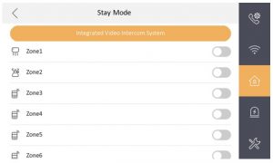 Figure 1-7 Arming Mode Settings
Information ManagementYou can view public notice, visitor message, alarm log and capture log on information management page.Tap Message to enter the information management page. (Here takes the alarm log page as an example.) Figure 1-8 Alarm LogsDelete a Log: Hold the item, you can delete it.Clear Logs: Hold the item, you can clear all logs.See Details: Hold a alarm log, you can see the alarm details.
![]() Note
Note
- Indoor extension only supports alarm log and capture log.
- It requires TF card for saving the notice, visitor messages and capture logs of the indoor stations, and requires the internal memory of the indoor station to save the alarm log.
- Up to 200 notices, 200 visitor messages, 200 alarm logs, and 200 capture logs can be saved.
Remote Operation via the client software
The Video Intercom module provides remote control and configuration on video intercom products via the iVMS-4200 client software.Call Indoor StationSteps
- Click on the left icon bar to enter the Video Intercom page.Figure 2-1 Call Indoor Station
- Select a resident and click in the Call Household column to start calling the selected resident.Figure 2-2 Calling Indoor Station
- After answered, you will enter the In Call window.
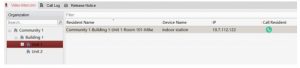 Figure 2-1 Call Indoor Station
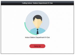 Figure 2-2 Calling Indoor Station
- Click to adjust the volume of the loudspeaker.
- Click to hang up.
- Click to adjust the volume of the microphone. Note
- One indoor station can only connect with one client software.
- You can set the maximum ring duration ranging from 15s to 60s, and the maximum speaking duration ranging from 120s to 600s via the Remote Configuration of indoor station.
Receive Call from Indoor Station/Door StationSteps
- Select the client software in the indoor station or door station page to start calling the client and an incoming call dialog will pop up in the client software.Figure 2-3 Incoming Call from Indoor Station
- Click Answer to answer the call. Or click Hang Up to decline the call.
- After you answer the call, you will enter the In Call window.
- Click to adjust the volume of the loudspeaker.
- Click to hang up.
- Click to adjust the volume of the microphone.
- For door station, you can click to open the door remotely.
- Click
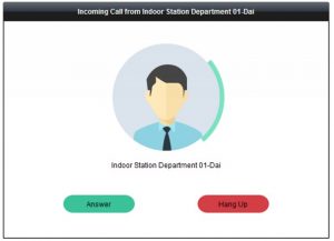 Figure 2-3 Incoming Call from Indoor Station
![]() Note
Note
- One video intercom device can only connect with one client software.
- The maximum ring duration can be set from 15s to 60s via the Remote Configuration of the video intercom device.
- The maximum speaking duration between indoor station and client can be set from 120s to 600s via the Remote Configuration of indoor station.
- The maximum speaking duration between door station and client can be set from 90s to 120s via the Remote Configuration of door station.
View Live Video of Door Station and Outer Door StationYou can get the live view of the door station and outer door station in the Main View module and control the door station and outer door station remotely. In the Main View module, double-click a door station or outer door station device or drag the device to a display window to start the live view.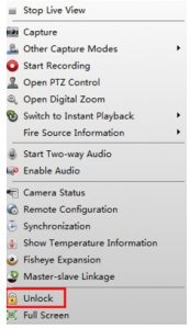 Figure 2-4 Tool ListYou can click Unlock on the menu to open the door remotely.View Call LogsYou can check all the call logs, including dialed call logs, received call logs and missed call logs. You can also directly dial via the log list and clear the logs.
Steps
- In the Video Intercom page, click the Call Log tab to enter the Call Log page. All the call logs will display on this page and you can check the log information, e.g., call status, start time, resident’s organization and name, device name and ring or speaking duration.Figure 2-5 Call Log
- Optional: Click the icon in the Operation column to re-dial the resident.
- Optional: Click the icon in the Operation column to delete the call log. Or you can click Clear at the upper right corner to clear all the logs.
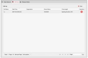 Figure 2-5 Call Log
Release NoticeYou can create different types of notices and send them to the residents. Four notice types are available, including Advertising, Property, Alarm and Notice Information. Steps
- In the Video Intercom page, click Release Notice to enter the Release Notice page.Figure 2-6 Release Notice
- Click New Notice on the left panel to create a new notice.
- Edit the notice on the right panel.
- Click icon + on the Send To field to pop up the Select Resident dialog.Figure 2-7 Select Resident
- Check the checkbox(es) to select the resident(s). Or you can check the All checkbox to select all the added residents.
- Click OK to save the selection.
- Enter the subject on the Subject field. NoteUp to 63 characters are allowed in the Subject field.
- Click in the Type field to unfold the drop-down list and select the notice type.
- Optional: Click Add Picture to add a local picture to the notice. NoteUp to 6 pictures in the JPGE format can be added to one notice. And the maximum size of one picture is 512KB.
- Enter the notice content in the Content field.
- Optional: You can also click Clear to clear the edited content. NoteUp to 1023 characters are allowed in the Content field.
- Click icon + on the Send To field to pop up the Select Resident dialog.
- Click Send to send the edited notice to the selected resident(s). The sent notice information will display on the left panel. You can click a notice to view the details on the right panel.
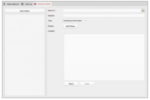 Figure 2-6 Release Notice
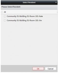 Figure 2-7 Select Resident
Search Video Intercom InformationYou can search the call logs between the iVMS-4200 client software and video intercom devices, device unlocking logs and the sent notice information. In the Access Control module, click ![]() to open the Search page.Search Call LogsSteps
to open the Search page.Search Call LogsSteps
- In the Information Search page, click Call Log to enter the Call Log page.Figure 2-8 Search Call Logs
- Set the search conditions, including call status, device type, start time and end time.Call StatusClick to unfold the drop-down list and select the call status as Dialed, Received or Missed. Or select All to search logs with all statuses.Device TypeClick to unfold the drop-down list and select the device type as Indoor Station, Door Station, Outer Door Station or Analog Indoor Station. Or select All Devices to search logs with all device types.Start Time/End TimeClick to specify the start time and end time of a time period to search the logs.
- Optional: You can click Reset to reset all the configured search conditions.
- Click Search and all the matched call logs will display on this page.
- Check the detailed information of searched call logs, such as call status, ring/ speaking duration, device name, resident organization, etc.
- Input keywords in the Search field to filter the desired log.
- Click Export to export the call logs to your PC.
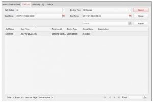 Figure 2-8 Search Call Logs
Search Unlocking LogsSteps
- In the Information Search page, click Unlocking Log to enter the Unlocking Log page.Figure 2-9 Unlocking Logs
- Set the search conditions, including unlocking type, device type, start time and end time.Unlocking TypeClick to unfold the drop-down list and select the unlocking type as Unlock by Password, Unlock by Duress, Unlock by Card, Unlock by Resident or Unlock by Center. Or select All to search logs with all unlocking types.Device TypeClick to unfold the drop-down list and select the device type as Door Station. Or select All Devices to search logs with all device types.Start Time/End TimeClick to specify the start time and end time of a time period to search the logs.
- Optional: You can click Reset to reset all the configured search conditions.
- Click Search and all the matched unlocking logs will display on this page.
- Check the detailed information of searched unlocking logs, such as unlocked time, card No., device No., etc.
- Input keywords in the Search field to filter the searching result.
- Click in the Capture column to view the captured pictures.
- Click Export to export the unlocking logs to your PC.
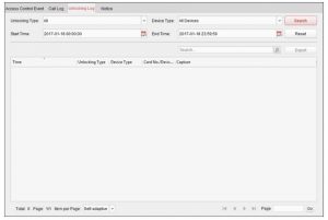 Figure 2-9 Unlocking Logs
 to specify the start time and end time of a time period to search the logs.
![]() NoteViewing captured picture should be supported by device. Search NoticeSteps
NoteViewing captured picture should be supported by device. Search NoticeSteps
- In the Information Search page, click Notice to enter the Notice page.Figure 2-10 Search Notice
- Set the search conditions, including notice type, subject, recipient, start time and end time.Notice TypeClick to unfold the drop-down list and select the notice type as Advertising Information, Property Information, Alarm Information or Notice Information. Or select All to search notices with all types.SubjectInput the keywords in the Subject field to search the matched notice.RecipientInput the recipient information in the Recipient field to search the specified notice.Start Time/End TimeClick to specify the start time and end time of a time period to search the notices.
- Optional: You can click Reset to reset all the configured search conditions.
- Click Search and all the matched notices will display on this page.
- Check the detailed information of searched notices, such as sending time, sending status, etc.
- Input keywords in the Search field to filter the searching result.
- Click in the Operation column to pop up Notice Details dialog.Figure 2-11 Message Details
- You can view and edit the notice details, check the sending failed/sent succeeded/unread users, and resend the notice to sending failed/unread users.
- Optional: Click Export to export the notices to your PC.
 Figure 2-10 Search Notice
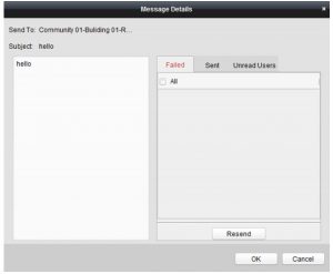 Figure 2-11 Message Details
[xyz-ips snippet=”download-snippet”]