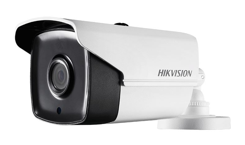
HIKVISION TURBO HD D8T Series
Bullet Camera User Manual
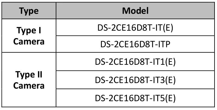
User ManualThank you for purchasing our product. If there are any questions, or requests, do not hesitate to contact the dealer. This manual applies to the models below:
This manual may contain several technical incorrect places or printing errors, and the content is subject to change without notice. The updates will be added to the new version of this manual. We will readily improve or update the products or procedures described in the manual.
0100001070415
Regulatory Information
FCC InformationPlease take attention that changes or modification not expressly approved by the party responsible for compliance could void the user’s authority to operate the equipment. FCC compliance: This equipment has been tested and found to comply with the limits for a Class A digital device, pursuant to part 15 of the FCC Rules. These limits are designed to provide reasonable protection against harmful interference when the equipment is operated in a commercial environment. This equipment generates, uses, and can radiate radio frequency energy and, if not installed and used in accordance with the instruction manual, may cause harmful interference to radio communications. Operation of this equipment in a residential area is likely to cause harmful interference in which case the user will be required to correct the interference at his own expense.
FCC ConditionsThis device complies with part 15 of the FCC Rules. Operation is subject to the following two conditions: 1. This device may not cause harmful interference. 2. This device must accept any interference received, including interference that may cause undesired operation.
EU Conformity Statement![]() This product and – if applicable – the supplied accessories too are marked with “CE” and comply therefore with the applicable harmonized European standards listed under the Low Voltage Directive 2014/35/EU, the EMC Directive 2014/30/EU.
This product and – if applicable – the supplied accessories too are marked with “CE” and comply therefore with the applicable harmonized European standards listed under the Low Voltage Directive 2014/35/EU, the EMC Directive 2014/30/EU.
 2012/19/EU (WEEE directive): Products marked with this symbol cannot be disposed of as unsorted municipal waste in the European Union. For proper recycling, return this product to your local supplier upon the purchase of equivalent new equipment, or dispose of it at designated collection points. For more information see: www.recyclethis.info. 2006/66/EC (battery directive):
![]() This product contains a battery that cannot be disposed of as unsorted municipal waste in the European Union. See the product documentation for specific battery information. The battery is marked with this symbol, which may include lettering to indicate cadmium (Cd), lead (Pb), or mercury (Hg). For proper recycling, return the battery to your supplier or to a designated collection point. For more information see: www.recyclethis.info.
This product contains a battery that cannot be disposed of as unsorted municipal waste in the European Union. See the product documentation for specific battery information. The battery is marked with this symbol, which may include lettering to indicate cadmium (Cd), lead (Pb), or mercury (Hg). For proper recycling, return the battery to your supplier or to a designated collection point. For more information see: www.recyclethis.info.
Industry Canada ICES-003 ComplianceThis device meets the CAN ICES-3 (A)/NMB-3(A) standards requirements.
Safety Instruction
These instructions are intended to ensure that user can use the product correctly to avoid danger or property loss.
The precaution measure is divided into “Warnings” and “Cautions”.
Warnings: Serious injury or death may occur if any of the warnings are neglected. Cautions: Injury or equipment damage may occur if any of the cautions are neglected.
Warnings Follow these safeguards to prevent serious injury or death.
Cautions Follow these precautions to prevent potential injury or material damage.
Warnings
- In the use of the device, you must be in strict compliance with the electrical safety regulations of the nation and region.
- Input voltage should meet both the SELV (Safety Extra Low Voltage) and the Limited Power Source with 12 VDC according to the IEC60950-1 standard. Refer to technical specifications for detailed information.
- Do not connect multiple devices to one power adapter to avoid over-heating or a fire hazard caused by overload.
- Make sure that the plug is firmly connected to the power socket.
- Make sure that the device is firmly fixed if wall mounting or ceiling mounting is adopted.
- If smoke, odor or noise rise from the device, turn off the power at once and unplug the power cord, and then contact the service center.
- Never attempt to disassemble the camera by unprofessional personal.
Cautions
- Do not drop the camera or subject it to physical shock.
- Do not touch senor modules with fingers.
- If cleaning is necessary, use clean cloth with a bit of ethanol and wipe it gently. Do not aim the camera at the sun or extra bright places.
- The sensor may be burned out by a laser beam, so when any laser equipment is in using, make sure that the surface of sensor will not be exposed to the laser beam.
- Do not expose the device to high electromagnetic radiation or extremely hot, cold, dusty or damp environment.
- To avoid heat accumulation, good ventilation is required for the operating environment. Keep the camera away from liquid while in use for non-water-proof device.
- While in delivery, the camera shall be packed in its original packing, or packing of the same texture.
Introduction
Product Features
The camera is applicable for both indoor and outdoor conditions, and the application scenarios include road, warehouse, underground parking lot, bar, etc..
The main features are as follows:
- High performance CMOS sensor
- Low illumination, 0.005 Lux @ (F2.0, AGC ON), 0 Lux with IR
- IR cut filter with auto switch
- OSD menu with configurable parameters
- Auto white balance
- internal synchronization
- SMART IR mode
- PoC (with -E)
- 3-axis adjustment
Overview
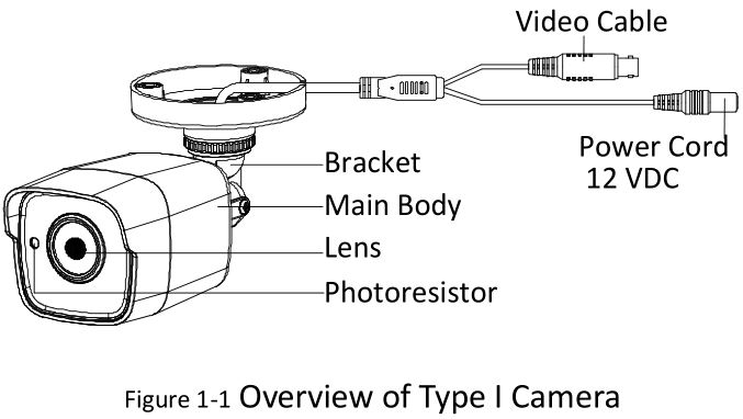
This manual applies to two types of bullet cameras. The overviews of each type are shown in the figures below.
Overview of Type I Camera
Overview of Type II Camera

Installation
Before you start:
- Make sure that the device in the package is in good condition and all the assembly parts are included.
- Make sure that all the related equipment is power-off during the installation.
- Check the specification of the products for the installation environment.
- Check whether the power supply is matched with your power output to avoid the damage.
- Make sure the wall is strong enough to withstand three times the weight of the camera and the bracket.
- If the wall is cement, insert expansion bolts before installing the camera. If the wall is wooden, use self-tapping screws to secure the camera.
- If the product does not function properly, contact your dealer or the nearest service center. Do NOT disassemble the camera for repair or maintenance by yourself.
Installation of Type I Camera
Ceiling/Wall Mounting without Junction Box
Steps:
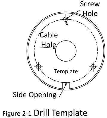
- Paste the drill template (supplied) to the place where you want to install the camera.
- Drill the screw holes and the cable hole (optional) in the ceiling/wall according to the drill template.
 Note: Drill the cable hole, when adopting the ceiling outlet to route the cable.
 - Attach the bracket to the ceiling/wall and secure the camera with supplied screws. Note:
- The supplied screw package contains self-tapping screws, and expansion bolts.
- For cement wall/ceiling, expansion bolts are required to fix the camera. For wooden wall/ceiling, self-tapping screws are required.
- Route the cables through the cable hole, or the side opening.
- Connect the corresponding power cord, and video cable.
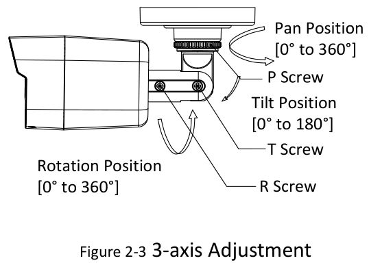
- Power on the camera to check whether the image on the monitor is gotten from the optimum angle. If not, adjust the camera according to the figure below to get an optimum angle.
- Loosen the P screw to adjust the pan position [0° to 360°]. Tighten the screw after completing the adjustment.
- Loosen the T screw to adjust the tilt position [0° to 180°]. Tighten the screw after completing the adjustment.
- Loosen the R screw and rotate the camera [0° to 360°]. Tighten the screw after completing the adjustment.
 Note: Drill the cable hole, when adopting the ceiling outlet to route the cable.
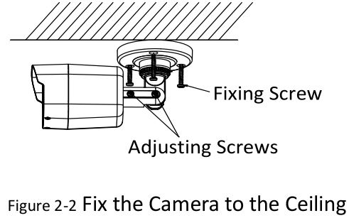 Note:
Note:
Ceiling/Wall Mounting with Junction Box
Before you start: You need to purchase a junction box separately.
Steps:
- Paste the drill template on the ceiling/wall.
- Drill screw holes and the cable hole in the ceiling/wall according to the holes of the drill template.
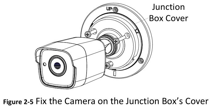
- Take apart the junction box, and align the screw holes of the bullet camera with those on the Junction box’ cover.
- Fix the camera on the junction box’s cover with supplied screws. Junction Box Cover
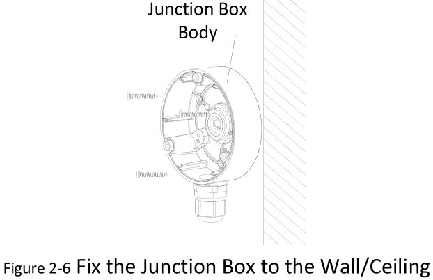
- Attach the junction box body to the ceiling/wall by aligning the screw holes of the junction box.
- Secure the junction box’s body with supplied screws on the ceiling/wall. Junction Box Body
- Route the cables through the bottom cable hole, or the side cable hole of the junction box.
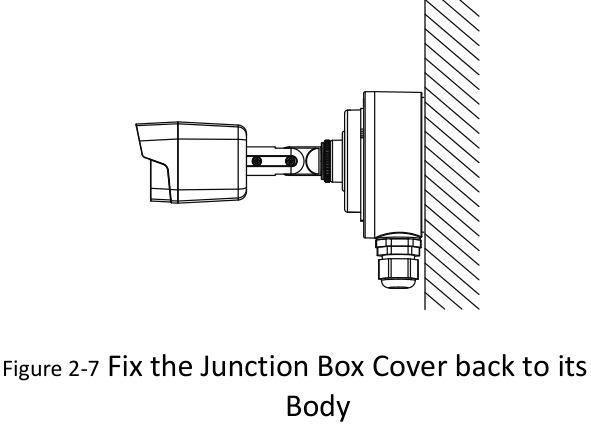
- Combine the junction box cover with its body.
- Repeat the step 5 and 6 of 2.1.1 Ceiling/Wall Mounting without Junction Box to complete the installation.
Installation of Type II Camera
Ceiling/Wall Mounting without Junction Box
Steps:
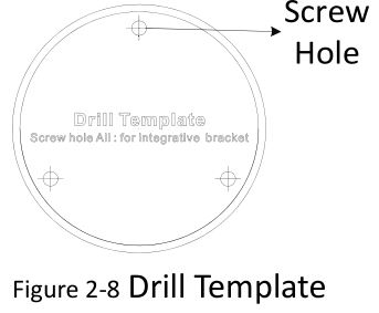
- Paste the drill template (supplied) to the place where you want to install the camera.
- Drill the screw holes according to the drill template, and the cable hole (optional) on the ceiling. Screw HoleNote: Drill the cable hole in the center of the drill template, when adopting ceiling outlet to route the cable.
- Route the cables through the cable hole (optional) or the side opening.
- Fix the camera to the ceiling with supplied screws.Note: The supplied screw package contains self-tapping screws, and expansion bolts. For cement wall/ceiling, expansion bolts are required to fix the camera. For wooden wall/ceiling, self-tapping screws are required.
- Connect the corresponding power cord, and video cable.
- Power on the camera to check whether the image on the monitor is gotten from the optimum angle. If not, adjust the surveillance angle.
- Loosen the No.1 adjusting screw to adjust the pan position [0° to 360°]. Tighten the No.1 adjusting screw.
- Loosen the No.2 adjusting screw to adjust the tilting position [0° to 180°]. Tighten the No. 2 adjusting screw.
- Loosen the No.3 adjusting screw to adjust the rotation position [0° to 360°]. Tighten the No.3 adjusting screw.
 Note: Drill the cable hole in the center of the drill template, when adopting ceiling outlet to route the cable.
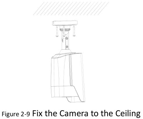 Note: The supplied screw package contains self-tapping screws, and expansion bolts. For cement wall/ceiling, expansion bolts are required to fix the camera. For wooden wall/ceiling, self-tapping screws are required.
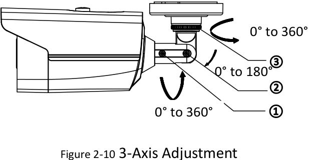
Ceiling/Wall Mounting with Junction Box
Before you start: You need to purchase a junction box separately.
Steps:
- Paste the drill template on the ceiling/wall.
- Drill screw holes and the cable hole (optional) in the ceiling/wall according to the holes of the drill template.Note: Drill the cable hole, when adopting ceiling outlet to route the cable.
- Take apart the junction box, and align the screw holes of the bullet camera with those on the Junction box’s cover.
- Fix the camera on the junction box’s cover with three supplied screws.
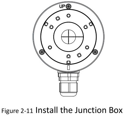
- Secure the junction box’s body with supplied screws on the ceiling/wall.
- Route the cables through the bottom cable hole, or the side cable hole of the junction box.
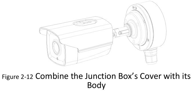
- Combine the junction box cover with its body with supplied screws on the junction box’s cover.
- Repeat the step 5 and 6 of 2.2.1 Ceiling/Wall Mounting without Junction Box to complete the installation.
Purpose: Call the menu by clicking button on the PTZ Control interface, or call preset No.95.
Steps:
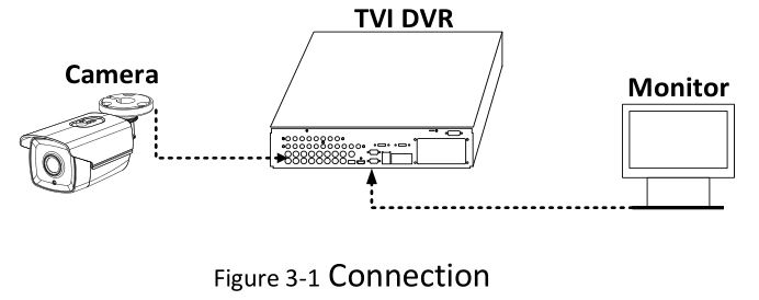
- Connect the camera with the TVI DVR, and the monitor, shown as the figure 3-1.
- Power on the analog camera, TVI DVR, and the monitor to view the image on the monitor.
- Click PTZ Control to enter the PTZ Control interface.
- Call the camera menu by clicking button, or call preset No. 95.
- Click the direction arrow to control the camera.
- Click up/down direction button to select the item.
- Click Iris + to confirm the selection.
- Click left/right direction button to adjust the value of the selected item.
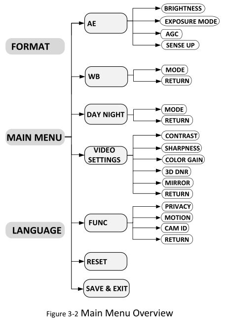
FORMAT
PAL (Phase Alternating Lines)PAL is a color encoding system for analog television used in broadcast television systems in most countries.
NTSC: (National Television System Committee)NTSC is the analog television system that is used in most of North America, parts of South America, Myanmar, South Korea, etc.
LANGUAGE
Supports English, and Chinese.
AE (AUTO EXPOSURE)
Auto Exposure describes the brightness-related parameters, which can be adjusted by BRIGHTNESS, EXPOSURE MODE, AGC, and SENSE UP.
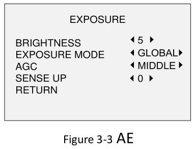
Brightness
Brightness refers to the brightness of the image. You can set the brightness value from 1 to 10 to darken or brighten the image. The higher the value, the brighter the image is.
EXPOSURE MODE
You can set the EXPOSURE MODE as GLOBAL, BLC, and WDR.
- GLOBAL
GLOBAL refers to the normal exposure mode which adjusts lighting distribution, variations, and non-standard processing.
- BLC (Backlight Compensation)
BLC (Backlight Compensation) compensates light to the object in the front to make it clear, but this may cause the over-exposure of the background where the light is strong. When BLC is selected as the exposure mode, the BLC level can be adjusted from 0 to 8.
- WDR (Wide Dynamic Range)
The wide dynamic range helps the camera provide clear images even under backlight circumstances. WDR balances the brightness level of the whole image and provides clear images with details.
- AGC (Auto Gain Control)
It optimizes the clarity of the image in poor light conditions. The GAIN level can be set as HIGH, MIDDLE, or LOW. Select OFF to disable the GAIN function.
Note: The noise will be amplified when the GAIN is on.
SENSE UP
Sense up increases the exposure on a signal frame, which makes a camera more sensitive to light so it can produce images even in low lux conditions. You can set the SENS-UP as OFF or AUTO according to different light conditions.
The SENS-UP function will atomically adjust itself to x2, x4, x6, x8, x10, x12, x14, and x16 according to the different light conditions.
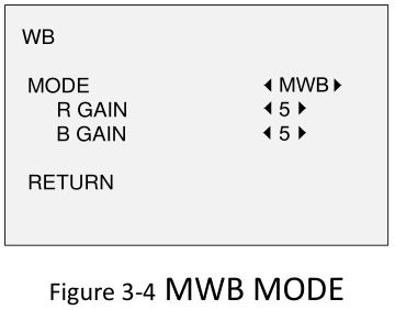
WB (White Balance)
White balance, the white rendition function of the camera, is to adjust the color temperature according to the environment. It can remove unrealistic color casts in the image. You can set WB mode as ATW, or MWB.
ATW (Aoto Tracking White Balance)
Under ATW mode, white balance is being adjusted automatically according to the color temperature of the scene illumination.
MWB (Manual White Balance)You can set the R GAIN/B GAIN value from 1 to 255 to adjust the shades of red/blue color of the image.
DAY NIGHT
Color, BW (Black White), and AUTO are selectable for DAY and NIGHT switches.
COLORThe image is colored in day mode all the time.
B/WThe image is black and white all the time, and the IR LED turns on in the low-light conditions.
AUTOYou can turn on/off the INFRARED and set the value of SMART IR in this menu.
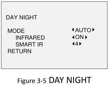
- INFRAREDYou can turn on/off the IR LED to meet the requirements of different circumstances.
- SMART IRThe Smart IR function is used to adjust the light to its most suitable intensity, and prevent the image from over exposure. The SMART IR value can be adjusted from 1 to 8. The higher the value the more obvious effects are.
VIDEO SETTING
Move the cursor to VIDEO SETTING and click Iris+ to enter the submenu. CONTRAST, SHARPNESS, COLOR GAIN, 3D DNR, and MIRROR are adjustable.
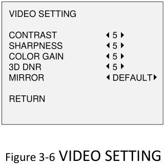
CONTRASTThis feature enhances the difference in color and light between parts of an image. You can set the CONTRAST value from 1 to 10.
SHARPNESSSharpness determines the amount of detail an imaging system can reproduce. You can set the SHARPNESS value from 1 to 10.
COLOR GAINAdjust this feature to change the saturation of the color. The value ranges from 1 to 10.
3D DNR (Digital Noise Reduction)The 3D DNR function can decrease the noise effect, especially when capturing moving images in low light conditions and delivering more accurate and sharp image quality. You can set the DNR value from 1 to 10.
MIRRORDEFAULT, H, V, and HV are selectable for mirror.DEFAULT: The mirror function is disabled.H: The image flips 180° horizontally.V: The image flips 180° vertically.HV: The image flips 180° both horizontally and vertically.
FUNC (Functions)
In the FUNC sub-menu, you can set the privacy mask, the motion detection, and camera ID of the camera.
PRIVACYThe privacy mask allows you to cover certain areas which you don’t want to be viewed or recorded. Up to 4 privacy areas are configurable.

Select a PRIVACY area. Set the DISPLAY status as ON. Click up/down/left/down button to define the position and size of the area.
MOTIONIn the user-defined motion detection surveillance area, the moving object can be detected and the alarm will be triggered. Up to 4 motion detection areas can be configured.
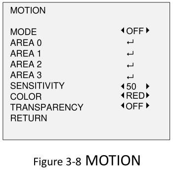
Select a MOTION area. Set the DISPLAY status as ON. Click the up/down/left/right button to define the position and size of the area. Set the SENSITIVITY from 0 to 100.
CAMERA IDEdit the camera ID on this section.
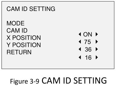
Set the MODE as on. Click up/don left/right button to choose the camera ID and the position.
RESET
Reset all the settings to the default.
SAVE & EXIT
Move the cursor to SAVE & EXIT and click Iris+ to save the setting and exit the menu.
References
[xyz-ips snippet=”download-snippet”]