
Video Intercom Door Station

Video Intercom Door Station(D Series)Quick Start GuideUD02925B
Video Intercom Door Station ·Quick Start GuideQuick Start Guide ©2016 Hangzhou Hikvision Digital Technology Co., Ltd.
This quick start guide is intended for users of the models below:
Series |
Model |
|
Door Station (D Series) |
DS-KD8102-V |
|
DS-KD8002-VM |
|
|
DS-KD6002-VM |
It includes instructions on how to use the Product. The software embodied in the Product is governed by the user license agreement covering that Product.
About this ManualThis Manual is subject to domestic and international copyright protection. Hangzhou Hikvision Digital Technology Co., Ltd. (“Hikvision”) reserves all rights to this manual. This manual cannot be reproduced, changed, translated, or distributed, partially or wholly, by any means, without the prior written permission of Hikvision.
Trademarks Hikvision and other Hikvision marks are the property of Hikvision and areregistered trademarks or the subject of applications for the same by Hikvision and/or its affiliates. Other trademarks mentioned in this manual are the properties of their respective owners. No right of license is given to use such trademarks without express permission.
DisclaimerTO THE MAXIMUM EXTENT PERMITTED BY APPLICABLE LAW, HIKVISION MAKES NO WARRANTIES, EXPRESS OR IMPLIED, INCLUDING WITHOUT LIMITATION THE IMPLIED WARRANTIES OF MERCHANTABILITY AND FITNESS FOR A PARTICULAR PURPOSE, REGARDING THIS MANUAL. HIKVISION DOES NOT WARRANT, GUARANTEE, OR MAKE ANY REPRESENTATIONS REGARDING THE USE OF THE MANUAL, OR THE CORRECTNESS, ACCURACY, OR RELIABILITY OF INFORMATION CONTAINED HEREIN. YOUR USE OF THIS MANUAL AND ANY RELIANCE ON THIS MANUAL SHALL BE WHOLLY AT YOUR OWN RISK AND RESPONSIBILITY.
TO THE MAXIMUM EXTENT PERMITTED BY APPLICABLE LAW, IN NO EVENT WILL HIKVISION, ITS DIRECTORS, OFFICERS, EMPLOYEES, OR AGENTS BE LIABLE TO YOU FOR ANY SPECIAL, CONSEQUENTIAL, INCIDENTAL, OR INDIRECT DAMAGES, INCLUDING, AMONG OTHERS, DAMAGES FOR LOSS OF BUSINESS PROFITS, BUSINESS INTERRUPTION, SECURITY BREACHES, OR LOSS OF DATA OR DOCUMENTATION, IN CONNECTION WITH THE USE OF OR RELIANCE ON THIS MANUAL, EVEN IF HIKVISION HAS BEEN ADVISED OF THE POSSIBILITY OF SUCH DAMAGES.
Video Intercom Door Station·Quick Start Guide
SOME JURISDICTIONS DO NOT ALLOW THE EXCLUSION OR LIMITATION OF LIABILITY OR CERTAIN DAMAGES, SO SOME OR ALL OF THE ABOVE EXCLUSIONS OR LIMITATIONS MAY NOT APPLY TO YOU.
SupportShould you have any questions, please do not hesitate to contact your local dealer.
Video Intercom Door Station ·Quick Start Guide
Regulatory InformationFCC Information
Please take attention that changes or modification not expressly approved by the party responsible for compliance could void the user’s authority to operate the equipment.
FCC compliance: This equipment has been tested and found to comply with the limits for a Class B digital device, pursuant to part 15 of the FCC Rules. These limits are designed to provide reasonable protection against harmful interference in a residential installation. This equipment generates, uses and can radiate radio frequency energy and, if not installed and used in accordance with the instructions, may cause harmful interference to radio communications. However, there is no guarantee that interference will not occur in a particular installation. If this equipment does cause harmful interference to radio or television reception, which can be determined by turning the equipment off and on, the user is encouraged to try to correct the interference by one or more of the following measures:–Reorient or relocate the receiving antenna.–Increase the separation between the equipment and receiver.–Connect the equipment into an outlet on a circuit different from that to which the receiver is connected.–Consult the dealer or an experienced radio/TV technician for help.This equipment should be installed and operated with a minimum distance 20cm between the radiator and your body.
FCC Conditions
This device complies with part 15 of the FCC Rules. Operation is subject to the following two conditions:
- This device may not cause harmful interference.
- This device must accept any interference received, including interference that may cause undesired operation.
EU Conformity Statement
 This product and – if applicable – the supplied accessories too are marked with “CE” and comply therefore with the applicable harmonized European standards listed under the R&TTE Directive 1999/5/EC, the EMC Directive 2004/108/EC, the RoHS Directive 2011/65/EU.
 2012/19/EU (WEEE directive): Products marked with this symbol cannot be disposed of as unsorted municipal waste in the European Union. For proper recycling, return this product to your local supplier upon the purchase of equivalent new equipment, or dispose of it at designated collection points. For more information see: www.recyclethis.info
Video Intercom Door Station·Quick Start Guide
 2006/66/EC (battery directive): This product contains a battery that cannot be disposed of as unsorted municipal waste in the European Union. See the product documentation for specific battery information. The battery is marked with this symbol, which may include lettering to indicate cadmium (Cd), lead (Pb), or mercury (Hg). For proper recycling, return the battery to your supplier or to a designated collection point. For more information see: www.recyclethis.info
Industry Canada ICES-003 Compliance
This device meets the CAN ICES-3 (B)/NMB-3(B) standards requirements. This device complies with Industry Canada licence-exempt RSS standard(s). Operation is subject to the following two conditions:
- this device may not cause interference, and
- this device must accept any interference, including interference that may cause undesired operation of the device.
Under Industry Canada regulations, this radio transmitter may only operate using an antenna of a type and maximum (or lesser) gain approved for the transmitter by Industry Canada. To reduce potential radio interference to other users, the antenna type and its gain should be so chosen that the equivalent isotropically radiated power (e.i.r.p.) is not more than that necessary for successful communication.
Video Intercom Door Station·Quick Start Guide
Safety Instruction
These instructions are intended to ensure that user can use the product correctly to avoid danger or property loss. The precaution measure is divided into Warnings and Cautions: Warnings: Neglecting any of the warnings may cause serious injury or death. Cautions: Neglecting any of the cautions may cause injury or equipment damage.
|
|
|
|
Warnings Follow these safeguards to prevent serious injury or death. |
Cautions Follow these precautions to prevent potential injury or material damage. |
![]() Warnings
Warnings
- All the electronic operation should be strictly compliance with the electrical safety regulations, fire prevention regulations and other related regulations in your local region.
- Please use the power adapter, which is provided by normal company. The power consumption cannot be less than the required value.
- Do not connect several devices to one power adapter as adapter overload may cause over-heat or fire hazard.
- Please make sure that the power has been disconnected before you wire, install or dismantle the device.
- When the product is installed on wall or ceiling, the device shall be firmly fixed.
- If smoke, odors or noise rise from the device, turn off the power at once and unplugthe power cable, and then please contact the service center.
- If the product does not work properly, please contact your dealer or the nearest service center. Never attempt to disassemble the device yourself. (We shall not assume any responsibility for problems caused by unauthorized repair or maintenance.)
 Cautions
- Do not drop the device or subject it to physical shock, and do not expose it to highelectromagnetism radiation. Avoid the equipment installation on vibrations surface or places subject to shock (ignorance can cause equipment damage).
- Do not place the device in extremely hot (refer to the specification of the device for the detailed operating temperature), cold, dusty or damp locations, and do not expose it to high electromagnetic radiation.
- The device cover for indoor use shall be kept from rain and moisture.
Video Intercom Door Station·Quick Start Guide
- Exposing the equipment to direct sun light, low ventilation or heat source such asheater or radiator is forbidden (ignorance can cause fire danger).
- Do not aim the device at the sun or extra bright places. A blooming or smear mayoccur otherwise (which is not a malfunction however), and affecting the endurance of sensor at the same time.
- Please use the provided glove when open up the device cover, avoid direct contact with the device cover, because the acidic sweat of the fingers may erode the surface coating of the device cover.
- Please use a soft and dry cloth when clean inside and outside surfaces of the device cover, do not use alkaline detergents.
- Please keep all wrappers after unpack them for future use. In case of any failure occurred, you need to return the device to the factory with the original wrapper. Transportation without the original wrapper may result in damage on the device and lead to additional costs.
- Improper use or replacement of the battery may result in hazard of explosion. Replace with the same or equivalent type only. Dispose of used batteries according to the instructions provided by the battery manufacturer.
Video Intercom Door Station·Quick Start Guide
1 Appearance1.1 Appearance of DS-KD8102-V
 Figure 1-1 Front View
 Figure 1-2 Side View
Table 1-1 Descriptions of Keys
No. |
Description |
|
1 |
Low Illumination Supplement Light |
|
2 |
Built-in Camera |
|
3 |
LCD Display Screen |
|
4 |
Keypad |
|
5 |
Call Button |
|
6 |
Call Center Key |
|
7 |
Microphone |
|
8 |
Card Induction Area |
|
9 |
IR Emission |
|
10 |
IR Receiver |
|
11 |
Loudspeaker |
|
12 |
TAMPER |
1.2 Appearance of DS-KD8002-VM
 Figure 1-3 Front View
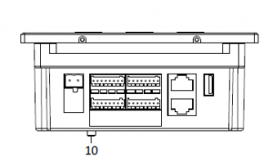 Figure 1-4 Side View
Table 1-2 Descriptions of Keys
No. |
Description |
|
1 |
Low Illumination Supplement Light |
|
2 |
Built-in Camera |
|
3 |
LCD Display Screen |
|
4 |
Card Induction Area |
|
5 |
Loudspeaker |
|
6 |
Keypad |
|
7 |
Call Button |
|
8 |
Microphone |
|
9 |
Call Center Key |
|
10 |
TAMPER |
1.3 Appearance of DS-KD6002-VM
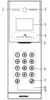 Figure 1-5 Front View
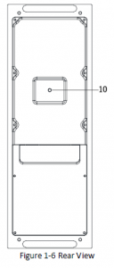 Figure 1-6 Rear View
Table 1-3 Descriptions Keys
|
No. |
Description |
|
1 |
Low Illumination Supplement Light |
|
2 |
Built-in Camera |
|
3 |
Loudspeaker |
No. |
Description |
|
4 |
LCD Display Screen |
|
5 |
Card Induction Area |
|
6 |
Keypad |
|
7 |
Call Button |
|
8 |
Call Center Key |
|
9 |
Microphone |
|
10 |
TAMPER |
2 Terminals and Interfaces2.1 Terminals and Interfaces of DS-KD8102-V/ DS-KD8002-VM
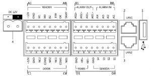
Figure 2-1 Terminals and Interfaces of DS-KD8102-V/DS-KD8002-VM
Table 2-1 Descriptions of Terminals and Interfaces
Name |
No. |
Interface |
Description |
|
USB |
1 |
USB |
USB Interface |
|
LAN |
2 |
LAN1 |
Network Interface |
|
3 |
LAN2 |
Analog Interface |
|
|
Power Supply |
4 |
DC 12V |
DC 12V Power Supply Input |
|
READER |
A1 |
12V |
Card Reader Power Supply Output |
|
A2 |
GND |
Grounding |
|
|
A3 |
W1 |
Data Input Interface Wiegand Card Reader: Data1 |
|
|
A4 |
W0 |
Data Input Interface Wiegand Card Reader: Data0 |
|
|
A5 |
BZ |
Card Reader Buzzer Output |
Name |
No. |
Interface |
Description |
|
A6 |
ERR |
Card Reader Indicator Output (Invalid Card Output) |
|
|
A7 |
OK |
Card Reader Indicator Output (Valid Card Output) |
|
|
A8 |
TAMP |
Tamper-proof Input of Wiegand Card Reader |
|
|
ALARM OUT |
B1 |
AO2- |
Alarm Relay Output 2 |
|
B2 |
AO2+ |
||
|
B3 |
AO1- |
Alarm Relay Output 1 |
|
|
B4 |
AO1+ |
||
|
ALARM IN |
B5 |
AI4 |
Alarm Input 4 |
|
B6 |
AI3 |
Alarm Input 3 |
|
|
B7 |
AI2 |
Alarm Input 2 |
|
|
B8 |
AI1 |
Alarm Input 1 |
|
|
DOOR |
C1 |
12V |
Door Lock Power Supply Output |
|
C2 |
GND |
Grounding |
|
|
C3 |
NC2 |
Door Lock Relay Output/Connect Electric Bolt or Magnetic Lock |
|
|
C4 |
COM2 |
Grounding Signal |
|
|
C5 |
NO2 |
Door Lock Relay Output/Connect Electric Strike |
|
|
C6 |
NC1 |
Door Lock Relay Output/Connect Electric Bolt or Magnetic Lock |
|
|
C7 |
COM1 |
Grounding Signal |
|
|
C8 |
NO1 |
Door Lock Relay Output/Connect Electric Strike |
|
|
RS485 |
D1 |
GND |
RS-485 Communication Interfaces |
|
D2 |
485- |
||
|
D3 |
485+ |
||
|
SENSOR |
D4 |
GND |
Grounding Signal |
|
D5 |
S4 |
Door Magnetic Detection Input 4/Exit Button |
|
|
D6 |
S3 |
Door Magnetic Detection Input 3/Exit Button |
|
|
D7 |
S2 |
Door Magnetic Detection Input 2/Exit Button |
|
|
D8 |
S1 |
Door Magnetic Detection Input 1/Exit Button |
Video Intercom Door Station·Quick Start Guide2.2 Terminals and Interfaces of DS-KD6002-VM
Figure 2-2 Terminals and Interfaces of DS-KD6002-VM
Table 2-2 Descriptions of Terminals and Interfaces
Name |
No. |
Interface |
Description |
|
USB |
1 |
USB |
USB Interface |
|
LAN |
2 |
LAN1 |
Network Interface |
|
3 |
LAN2 |
Analog Interface |
|
|
Power Supply |
4 |
DC 12V |
DC 12V Power Supply Input |
|
READER |
A1 |
12V |
Card Reader Power Supply Output |
|
A2 |
GND |
Grounding |
|
|
A3 |
W1 |
Data Input Interface Wiegand Card Reader: Data1 |
|
|
A4 |
W0 |
Data Input Interface Wiegand Card Reader: Data0 |
|
|
A5 |
BZ |
Card Reader Buzzer Output |
|
|
A6 |
ERR |
Card Reader Indicator Output (Invalid Card Output) |
|
|
A7 |
OK |
Card Reader Indicator Output (Valid Card Output) |
|
|
A8 |
TAMP |
Tamper-proof Input of Wiegand Card Reader |
Name |
No. |
Interface |
Description |
|
ALARM OUT |
B1 |
AO2- |
Alarm Relay Output 2 |
|
B2 |
AO2+ |
||
|
B3 |
AO1- |
Alarm Relay Output 1 |
|
|
B4 |
AO1+ |
||
|
DEBUG |
B5 |
GND |
Grounding |
|
B6 |
RX |
Serial Port Debugging/Receive data |
|
|
B7 |
TX |
Serial Port Debugging/Send data |
|
|
B8 |
3.3V |
Serial Port Debugging/Power Supply |
|
|
DOOR |
C1 |
12V |
Door Lock Power Supply Output |
|
C2 |
GND |
Grounding |
|
|
C3 |
NC2 |
Door Lock Relay Output/Connect Electric Bolt or Magnetic Lock |
|
|
C4 |
COM2 |
Grounding Signal |
|
|
C5 |
NO2 |
Door Lock Relay Output/Connect Electric Strike |
|
|
C6 |
NC1 |
Door Lock Relay Output/Connect Electric Bolt or Magnetic Lock |
|
|
C7 |
COM1 |
Grounding Signal |
|
|
C8 |
NO1 |
Door Lock Relay Output/Connect Electric Strike |
|
|
RS485 |
D1 |
GND |
RS-485 Communication Interfaces |
|
D2 |
485- |
||
|
D3 |
485+ |
||
|
ALARM IN |
D4 |
GND |
Grounding Signal |
|
D5 |
AI4 |
Alarm Input 4 |
|
|
D6 |
AI3 |
Alarm Input 3 |
|
|
D7 |
AI2 |
Alarm Input 2 |
|
|
D8 |
AI1 |
Alarm Input 1 |
Video Intercom Door Station·Quick Start Guide
3 Installation and Wiring
Before you start:
- Make sure the device in the package is in good condition and all the assembly partsare included.
- The power supply the door station supports is 12 VDC. Please make sure your powersupply matches your door station.
- Make sure all the related equipment is power-off during the installation.
- Check the product specification for the installation environment.
3.1 Installation of DS-KD8102-V
To install the door station onto the wall, you are required to use a matched gang box.
3.1.1 Gang Box for DS-KD8102-V 404
Figure 3-1 Front and Side ViewFigure 3-2 Overhead (Plan) View 9
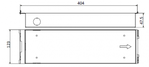 Figure 3-1 Front and Side View
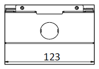 Figure 3-2 Overhead (Plan) View 9
Video Intercom Door Station·Quick Start Guide
- The dimension of gang box for model DS-KD8102-V door station is: 404 (length)×123 (width)×47.5 (depth) mm.
- The dimensions above are for reference only. The actual size can be slightly different from the theoretical dimension.
3.1.2 Wall Mounting with Gang Box of DS-KD8102-V
Steps:
- Chisel a hole in the wall for inserting the gang box. The size of the hole should belarger than that of the gang box. The suggested size of hole is 404.5 (length) × 123.5 (width) ×48 (depth) mm.
- Insert the gang box into the hole and fix it with 4 PA4 screws. Make sure the edges of the gang box align to the wall.Figure 3-3 Insert the Gang Box into the Wall
- Route the cables of the door station through the cable hole.
- Put the door station into the gang box and hook the lock catches on the rear panelonto the hook A and B of the gang box.Figure 3-4 Install the Door Station
- Pull the door station downward and then push it towards the inside to make sure it fits the hole.
- Tighten the screws of the door station with the Allen wrench.Figure 3-5 Tighten the Screws of Device
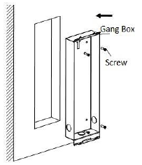 Figure 3-3 Insert the Gang Box into the Wall
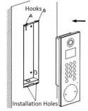 Figure 3-4 Install the Door Station
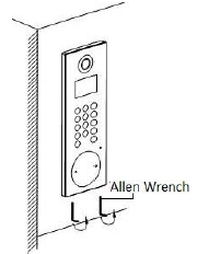 Figure 3-5 Tighten the Screws of Device
3.2 Installation of DS-KD8002-VM3.2.1 Gang Box for DS-KD8002-VM 407.5
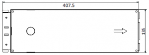 Figure 3-6 Front View
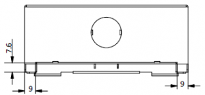 Figure 3-7 Overhead (Plan) View
- The dimension of gang box for model DS-KD8002-VM door station is: 407.5 mm × 135 mm × 55 mm.
- The dimensions above are for reference only. The actual size can be slightly larger than the theoretical dimension.
3.2.2 Wall Mounting with Gang Box of DS-KD8002-VM
- Chisel a hole in the wall for inserting the gang box. The size of the hole should be larger than that of the gang box. The suggested size of hole is 136 (length) × 408.5 (width) × 55.5 (depth) mm.Figure 3-8 Dimensions of the Hole
- Insert the gang box into the hole and fix it with 4 PA4 screws.Figure 3-9 Insert the Gang Box into the Wall
- Make sure the edges of the gang box align to the wall and the hook A and hook Bof the gang box hook onto the wall.
- Route the cables of the door station through the cable hole.
- Insert the door station into the gang box and then move the door station downward to hookthe lock catches on the rear panel onto the hook C of the gang box.
- Fix the door station with 2 PM3 screws.Figure 3-10 Install the Door Station
- After fixing the door station onto the gang box, secure it by inserting the plate and insert2 POM2 screws.Figure 3-11 Secure the Door Station 14
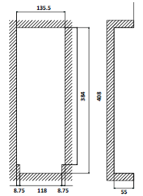 Figure 3-8 Dimensions of the Hole
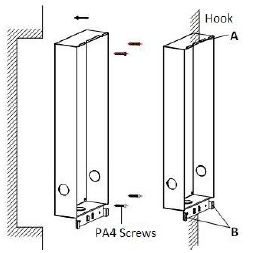 Figure 3-9 Insert the Gang Box into the Wall
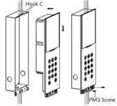 Figure 3-10 Install the Door Station
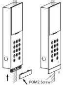 Figure 3-11 Secure the Door Station 14
3.3 Installation of DS-KD6002-VM3.3.1 Gang Box for DS-KD6002-VM
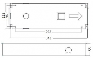
Figure 3-12 Front and Side View
- The dimension of gang box for model DS-KD6002-VM door station is:343(length)× 113(width)×55(depth) mm.
- The dimensions above are for reference only. The actual size can be slightlydifferent from the theoretical dimension.
3.3.2 Wall Mounting with Gang Box of DS-KD6002-VM
Steps: 1. Chisel a hole in the wall for inserting the gang box. The size of the hole should belarger than that of the gang box. The suggested size of hole is 343.5 (length) × 113.5 (width) × 55.5 (depth) mm. 2. Insert the gang box into the hole and fix it with 4 PA4 screws.
ScrewScrewFigure 3-13 Insert the Gang Box into the Wall 3. Make sure the edges of the gang box align to the wall. 4. Route the cables of the door station through the cable hole. 5. Put the door station into the gang box.Figure 3-14 Install the Door Station 6. Fix the door station to the gang box with 4 crews.16
Video Intercom Door Station·Quick Start GuideFigure 3-15 Tighten the Screws of Device3.4 Wiring Description3.4.1 Door Lock WiringFigure 3-16 Door Lock Wiring Terminal NO1/COM1 is set as default for accessing magnetic lock/electric bolt;terminal NC1/COM1 is set as default for accessing electric strike. 17
Video Intercom Door Station·Quick Start Guide To connect electric lock in terminal NO2/COM2/NC2, it is required to set the output ofterminal NO2/COM2/NC2 to be electric lock with Batch Configuration Tool or iVMS-4200.3.4.2 Door Magnetic WiringDoor Magnetic Wiring for DS-KD8102-V/DS-KD8002-VM For DS-KD8102-V/DS-KD8002-VM, there are two optional ways of door magnetic wiring.Figure 3-17 Door Magnetic Wiring for DS-KD8102-V/DS-KD8002-VM (1) To connect the door magnetic, it is required to set the output of terminal AI2 to be door magnetic with Batch Configuration Tool or iVMS-4200.Figure 3-18 Door Magnetic Wiring for DS-KD8102-V/DS-KD8002-VM (2) 18
Video Intercom Door Station·Quick Start Guide Terminal S2 is set as default for connecting door magnetic. Door Magnetic Wiring for DS-KD6002-VMFigure 3-19 Door Magnetic Wiring for DS-KD6002-VM To connect the door magnetic, it is required to set the output of terminal AI2 to be door magnetic with Batch Configuration Tool or iVMS-4200.3.4.3 Exit Button WiringExit Button Wiring for DS-KD8102-V/DS-KD8002-VM For DS-KD8102-V/DS-KD8002-VM, there are two optional ways of exit button wiring.Figure 3-20 Exit Button Wiring for DS-KD8102-V/DS-KD8002-VM (1) 19
Video Intercom Door Station·Quick Start Guide To connect the exit button, it is required to set the output of terminal AI1 to be exit button with Batch Configuration Tool or iVMS-4200.Figure 3-21 Exit Button Wiring for DS-KD8102-V/DS-KD8002-VM (2) Exit Button Wiring for DS-KD6002-VMFigure 3-22 Exit Button Wiring for DS-KD6002-VM Terminal S1 is set as default for connecting exit button.20
Video Intercom Door Station·Quick Start Guide3.4.4 External Card Reader Wiring
Please set the DIP switch first before connecting the card reader. If the DIP switch should be configured when the card reader is power-on, pleasereboot the card reader after configuring the DIP switch. The DIP switch description is shown in the following table:
No.
Description
How to Configure
1-4 Set the RS-485 address
ON: 1 OFF: 0
6 Select Wiegand protocol ON: Wiegand
or RS-485 protocol
OFF: RS-485
7 Set the Wiegand protocol ON: Wiegand 26 (It is invalid when setting OFF: Wiegand 34 OFF in 6.)
RS-485 Card Reader Wiring
Figure 3-23 RS-485 Card Reader Wiring 21
Video Intercom Door Station·Quick Start Guide Wiegand Card Reader WiringFigure 3-24 External Card Reader Wiring3.4.5 Alarm Device Input WiringAlarm Device Input Wiring for DS-KD8102-V/DS-KD8002-VMFigure 3-25 Alarm Device Input Wiring for DS-KD8102-V/DS-KD8002-VM 22
Video Intercom Door Station·Quick Start Guide Alarm Device Input Wiring for DS-KD6002-VMFigure 3-26 Alarm Device Input Wiring for DS-KD6002-VM3.4.6 Alarm Device Output WiringAlarm Device Output Wiring for DS-KD8102-VFigure 3-27 Alarm Device Output Wiring for DS-KD8102-V/DS-KD8002-VM23
Video Intercom Door Station·Quick Start Guide Alarm Device Output Wiring for DS-KD6002-VMFigure 3-28 Alarm Device Output Wiring for DS-KD6002-VM24
Video Intercom Door Station·Quick Start Guide4 Before You StartFor the first time use of the device, you are required to activate the device and set the device password. You can activate the device via internet with Batch Configuration Tool, or with iVMS-4200 client software.To activate the device with Batch Configuration Tool or iVMS-4200, refer to 6.1 Activating Device Remotely. To activate the device locally, refer to 5.1 Activating Device. To configure the key parameters of device on the user interface of door station, you are required to input the admin password. Here the admin password refers to the configuration password. The default admin password is 888999. You can set the login password of the device by yourself. You must change the default credential to protect against unauthorized access to the product. Please refer to 5.3 Changing Password.25
Video Intercom Door Station·Quick Start Guide5 Local Operation
Key descriptions of door stations are illustrated in the table below.
The number key 2
The number key 8
The number key 4
The number key 6
#
Call Key (When calling residents or center)
Delete *Return
5.1 Activating DeviceSteps: 1. Power on the device to enter the activation interface automatically.
2. Press the # key.
Figure 5-1 Activate the Device
26
Video Intercom Door Station·Quick Start GuideFigure 5-2 Set Password 3. Enter a new password, and confirm the password. 4. Press the # key to complete the activation.5.2 Editing Network ParametersPurpose: Network connection is mandatory for the use of door station. Steps: 1. Go to the configuration mode.1) Hold down the * key and the # key for 2s to enter the admin password interface. 2) Enter the admin password, and press the # key.Figure 5-3 Admin Password Interface The default admin password is 888999. 2. Enter the network parameters settings interface. 1) Press the number keys 4 and 6 to switch to the network configuration interface27
Video Intercom Door Station·Quick Start GuideFigure 5-4 Network Configuration Interface 2) Press the # key to enter the network parameters settings interface.Figure 5-5 Network Parameters Settings Interface 3. Edit network parameters.1) Move the cursor to parameters to be configured. 2) Press the # key to enter or exit the editing mode. 4. Press the * key to exit the network configuration interface after accomplishing network parameters settings.5.3 Changing PasswordPurpose: The default admin password is 888999. You should change the password for the security sake. Steps: 1. Go to the configuration mode.1) Hold down the * key and the # key for 2s to enter the admin password interface. 2) Enter the admin password, and press the # key.28
Video Intercom Door Station·Quick Start GuideFigure 5-6 Admin Password Interface The default admin password is 888999. 2. Enter the password settings interface. 1) Press the number keys 4 and 6 to switch to the password settings interfaceFigure 5-7 Password Settings Interface 2) Press the # key to enter the password changing interface.Figure 5-8 Password Changing Interface 3. Enter the old password, and the new password, and confirm the new one.1) Move the cursor to parameters to be configured. 2) Press the # key to enter or exit the editing mode.29
Video Intercom Door Station·Quick Start Guide4. Press the * key to exit the network configuration interface after changing the password.
5.4 Calling ResidentYou can call residents via the door station. The door station can work as main/sub door station, and outer door station, which correspond to different calling resident modes respectively.Working as Main/Sub Door Station Steps: 1. Enter the Room No..
2. Press the # key or the
key to start calling the resident.
Working as Outer Door StationSteps: 1. Enter the Community No. and the # key, the Building No. and the # key, the Unit No.and the # key, and the Room No. and the # key.
2. Press the
key to start calling the resident.
5.5 Unlocking DoorBefore you start: Make sure your door station works as the main/sub door station. Purpose: 2 ways are available to unlock the door: via entering the password, and via swiping the card.Unlocking Door by Password Steps: 1. Enter the # key and the Room No.. 2. Enter the password and the # key.
The password varies according to different rooms. The default password is 123456.
30
Video Intercom Door Station·Quick Start Guide Unlocking Door by Card Before you start: Make sure the card has been issued. You can issue the card via the door station, or via iVMS-4200 client software. Please refer to User Manual for detail steps. Steps: Swipe the card on the card induction area to unlock the door. The main card does not support unlocking the door.31
Video Intercom Door Station·Quick Start Guide6 Remote Operation via Batch Configuration Software6.1 Activating Device RemotelyPurpose: You are required to activate the device first by setting a strong password for it before you can use the device. Activation via Batch Configuration Tool, and Activation via iVMS-4200 are supported. Here take activation via Batch Configuration Tool as example to introduce the device activation. Please refer to the user manual for the activation via iVMS-4200. Steps: 1. Run the Batch Configuration Tool.Figure 6-1 Selecting Inactive Device 2. Select an inactivated device and click the Activate button.Figure 6-2 Activation 3. Create a password, and confirm the password.32
Video Intercom Door Station·Quick Start Guide STRONG PASSWORD RECOMMENDED We highly recommend you create astrong password of your own choosing (Using a minimum of 8 characters, including at least three of the following categories: upper case letters, lower case letters, numbers, and special characters.) in order to increase the security of your product. And we recommend you reset your password regularly, especially in the high security system, resetting the password monthly or weekly can better protect your product. 4. Click the OK button to activate the device.When the device is not activated, the basic operation and remote operation of device cannot be performed.You can hold the Ctrl or Shift key to select multiple devices in the online devices, and click the Activate button to activate devices in batch.6.2 Editing Network ParametersPurpose: To operate and configure the device via LAN (Local Area Network), you need connect the device in the same subnet with you PC. You can edit network parameters via batch configuration tool, and iVMS-4200 software. Here take editing network parameters via batch configuration tool as example. Steps: 1. Select an online activated device and click the Edit NET Parameters button.Figure 6-3 Clicking Edit NET Parameters Button 2. Change the device IP address and gateway address to the same subnet with yourcomputer. 3. Enter the password and click the OK button to activate the network parametersmodification.33
Video Intercom Door Station·Quick Start GuideFigure 6-4 Editing Network ParametersThe default port No. is 8000. After editing the network parameters of device, you should add the devices to thedevice list again.6.3 Adding DeviceFor batch configuration tool and iVMS-4200 software, you should add device to the software so as to configure the device remotely. 3 ways for adding the device are supported: adding active online devices within your subnet, adding device by IP address, and adding device by IP segment. Here take adding online device and adding device by IP address via batch configuration tool as example.6.3.1 Adding Online DeviceSteps: 1. Select an active online device or hold the Ctrl or Shift key to select multiple devices inthe online devices list.Figure 6-5 Online Devices Interface 2. Click the button to pop up the login dialog box.34
Video Intercom Door Station·Quick Start Guide
Figure 6-6 Login Dialog Box3. Enter the user name and password. 4. Click the OK button to save the settings.
Only devices successfully logged in will be added to the device list for configuration. If you add devices in batch, please make sure selected devices have the same username and password.
6.3.2 Adding by IP Address
Purpose: You can add the device by entering IP address.
Steps: 1. Click the
button to pop up the adding devices dialog box.
Figure 6-7 Adding Button 2. Select IP Address in the adding mode drop-down list. 3. Enter the IP address, and set the port No., user name and password of the device.
35
Video Intercom Door Station·Quick Start GuideFigure 6-8 Adding by IP Address 4. Click the OK button to add the device to the device list. You cannot add the device(s) to the device list if the user name and password are notidentical. When you add devices by IP Address, IP Segment or Port No., the devices should beonline devices.36
Video Intercom Door Station·Quick Start GuideAppendix
Installation NoticeWhile installing the indoor station, make sure that the distance between any two devices is far enough to avoid the howling and echo. The distance between two devices is recommended to be longer than 10 meters.
Here devices refer to indoor station, outdoor station and master station.
Wiring CablesCable Power Cord of Door Station Network Cable of Door Station Door Lock Wiring (With Door Magnetic) Door Lock Wiring (Without Door Magnetic)Exit Button Wiring External Card Reader Wiring
Specification RVV 2*1.0UTP-five Categories RVV 4*1.0 RVV 2*1.0 RVV 2*0.5RVVP 4*0.75
37
Video Intercom Door Station·Quick Start Guide 38
References
[xyz-ips snippet=”download-snippet”]