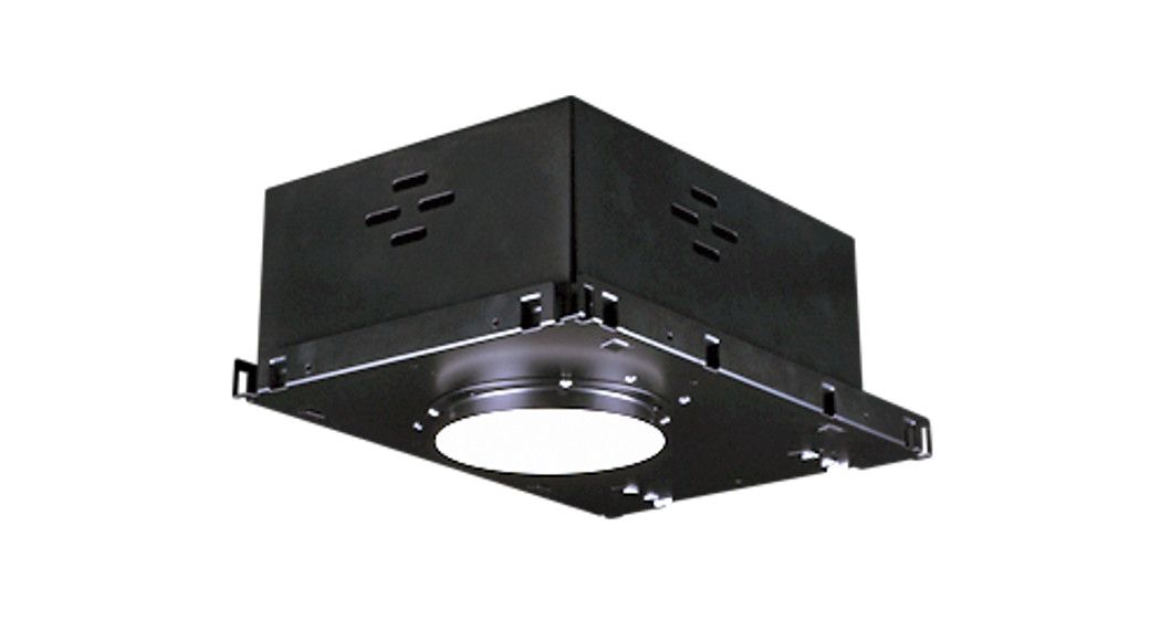
![]() LED DownlightsIMPORTANT INFORMATIONPlease Read Before Installing
LED DownlightsIMPORTANT INFORMATIONPlease Read Before Installing
Installation Instructions
Important Notes
- IC fixtures must be used for installations containing insulating materials and must be mounted away from heat-producing elements (e.g., HVAC ducts, hot water pipes, radiant heat floors, ovens). Non-IC fixtures cannot be used in these types of applications.
- Non-IC fixtures are intended for free-air applications. Do not confine Non-IC fixtures with insulation or building materials.
- Install and wire in accordance with national and local electrical codes, by a qualified professional familiar with the construction and operation of the luminaire electrical systems and the hazards involved.
- IC fixtures are rated for direct application of spray foam with less than R-21 insulative value or 3 in (76.2 mm) of closed-cell spray foam. 95 °F (35 °C) maximum operating temperature.
- The mud ring shipped with timeless fixtures must be installed to ensure a desirable ceiling aesthetic and to provide structural support.
- Hanger bars can be installed on either side of the fixture.
- Housings, modules, and trims are shipped in separate packages. Install modules and trims per housing labels (see Step 6a).
- Installation details with materials other than drywall or plaster, please see Application Note #564 at www.lutron.com.
- Sloped ceiling installation: Install housing with a junction box at bottom of the slope. Adjustable fixtures accommodate up to 40° slope (10/12 roof pitch).
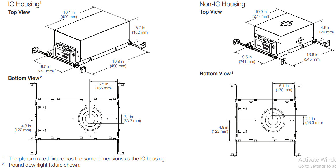
Dimensions
Fixture Installation
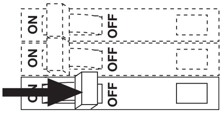
- Turn off the power.
 WARNING: Electric Shock Hazard. Serious Injury or Death may occur. Turn off power before servicing or installing. Wire according to local and national codes. This product should be installed by a qualified electrician
 - Install fixture using the hanger bar based on mounting method (Figure 1). Hanger bars can be installed on either side of the fixture.a. Insert hanger bars into hanger bar clamp.b. Use a hanger bar to secure to structure (notch allows for T-bar installation). Secure wires (not included) to the hanger bar (if required).c. Hammer barb into a stud or secure with mounting screws provided by others.
d. Optional: Use set screws provided to lock hanger bars.Notes: For T-bar installation details, please see Lutron Application Note #564. Hanger bars cannot be locked on the junction box side of the housing.
- Make power connections. See Circuit Diagrams for Dimming (Pg. 5). Note: Do not trim wire length from the LED controller (driver). Wire length is required for controller (driver) accessibility after the fixture is installed.
Fixture Installation (continued)
- Cut out drywall to fit fixture aperture. a. Round diameter: 4.6 in (117 mm). See page 6 for the template. b. Square dimensions: 4.1 in x 4.1 in (104 mm x 104 mm). See page 7 for the template. c. Install the cardboard housing insert from the product packaging to protect the LED module (Figure 2 on the previous page).
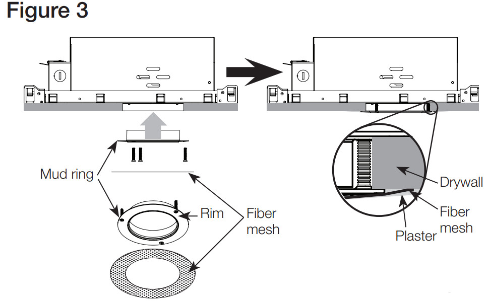
- Install mud ring (Trimless only) (Figure 3).a. Remove ceiling material to allow access to housing mud ring screw locations. If desired, use the cutout template at end of the installation guide.b. Insert provided screws into holes in mud ring and screw into housing.c. Use screws to level the mud ring to the ceiling.d. Ensure screws secure mud ring flush to drywall.e. Apply plaster up to the rim of the mud ring.Note: Use fiber mesh provide to increase the durability of the plaster joint.f. Smooth plaster to blend with the ceiling.
- Install LED module.Note: DO NOT touch the inside of the reflector or the LED.a. Match LED module number on module grab plate (Figure 4) to housing label, located inside the fixture housing.b. Connect LED module to housing. For types XX, NS, HO, HP, press in the red button on the connector to lock the connector in place.Note: Connectors are specific to housing/module compatibility.c. Install the module by pressing it up into the module support bracket.Note: Module must be installed into the keyway (Figure 4) of the module support bracket.
- For Adjustable fixtures, rotate the fixture to the desired location (Figure 4). a. Loosen rotation-locking thumb screw. b. Aim fixture by rotating the module support bracket to the desired position. c. Tighten thumbscrew.
- For Adjustable fixtures, adjust the tilt position of the fixture by moving the module support bracket along the track (Figure 5).Optional: Lock tilt position with tilt lock thumbscrew (Figure 4).Note: For Infinite Adjustable fixtures, turn tilt adjustment screw with Lutron supplied 9/64 in hex tool (Figure 6).
- Install the trim (Figure 7 on next page) by pushing the trim into opening until clips engage on sides. Use a damp cloth to clean the trim/lensNote: Tilt adjustment screw available for Infinite Adjustable fixtures only
 WARNING: Electric Shock Hazard. Serious Injury or Death may occur. Turn off power before servicing or installing. Wire according to local and national codes. This product should be installed by a qualified electrician
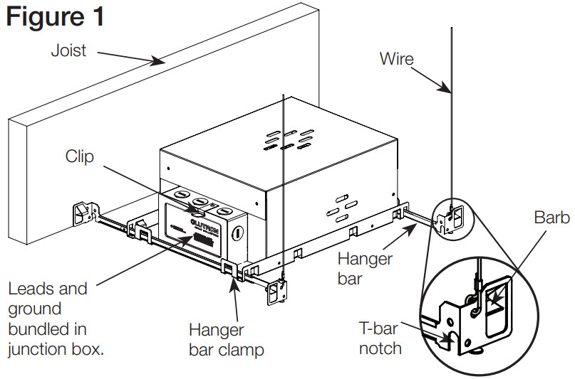 a. Insert hanger bars into hanger bar clamp.b. Use a hanger bar to secure to structure (notch allows for T-bar installation). Secure wires (not included) to the hanger bar (if required).c. Hammer barb into a stud or secure with mounting screws provided by others.
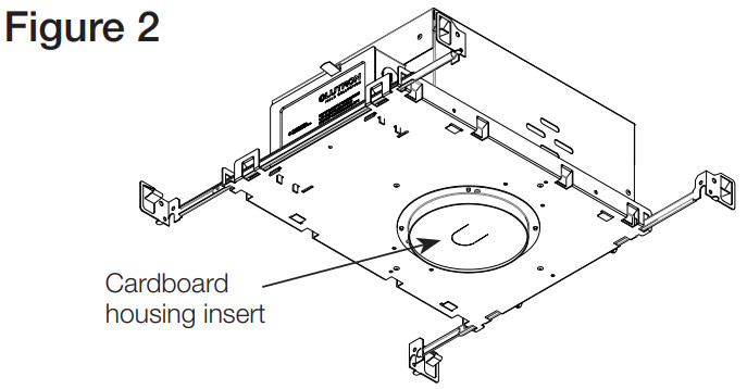
 a. Remove ceiling material to allow access to housing mud ring screw locations. If desired, use the cutout template at end of the installation guide.b. Insert provided screws into holes in mud ring and screw into housing.c. Use screws to level the mud ring to the ceiling.d. Ensure screws secure mud ring flush to drywall.e. Apply plaster up to the rim of the mud ring.Note: Use fiber mesh provide to increase the durability of the plaster joint.f. Smooth plaster to blend with the ceiling.
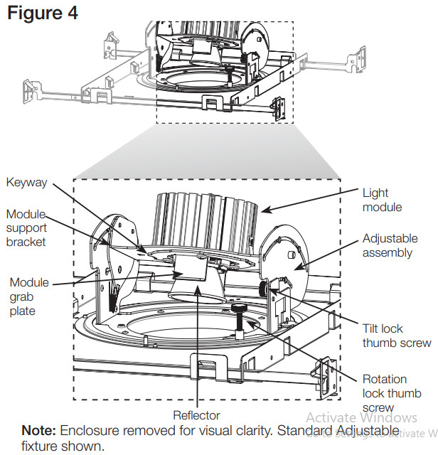 Note: DO NOT touch the inside of the reflector or the LED.a. Match LED module number on module grab plate (Figure 4) to housing label, located inside the fixture housing.b. Connect LED module to housing. For types XX, NS, HO, HP, press in the red button on the connector to lock the connector in place.Note: Connectors are specific to housing/module compatibility.c. Install the module by pressing it up into the module support bracket.Note: Module must be installed into the keyway (Figure 4) of the module support bracket.
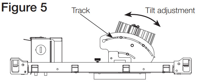 Optional: Lock tilt position with tilt lock thumbscrew (Figure 4).Note: For Infinite Adjustable fixtures, turn tilt adjustment screw with Lutron supplied 9/64 in hex tool (Figure 6).
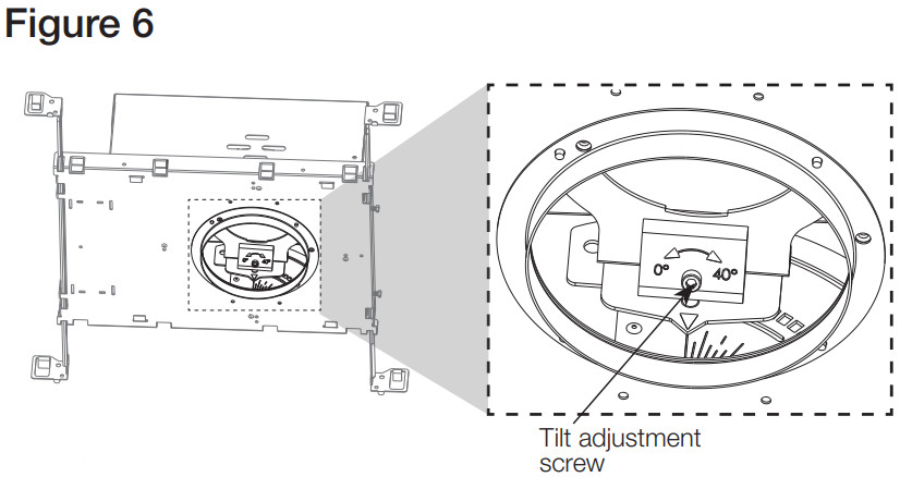 Note: Tilt adjustment screw available for Infinite Adjustable fixtures only
Restore power.
Field Replace Components (optional)
WARNING: Risk of Fire or Electric Shock. May result in serious injury or death. LED retrofit kit installation requires knowledge of luminaire electrical systems. If not qualified, do not attempt installation. Contact a qualified electrician. NOTICE: Property Damage. To prevent damage or abrasions, do not expose wiring to edges of sheet metal or other sharp objects.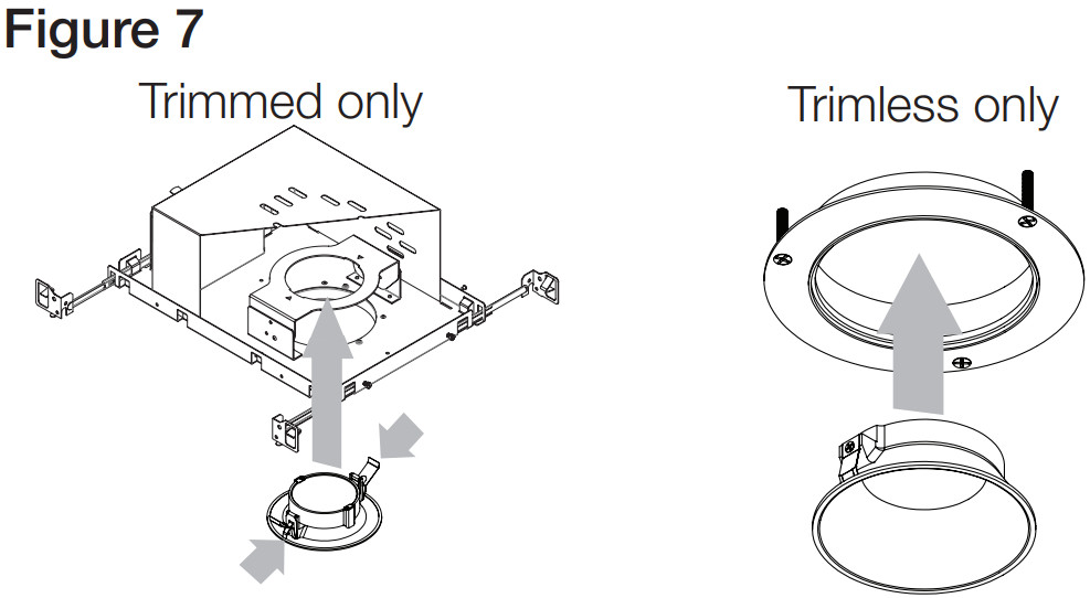
Note: Do not make or alter any open holes in an enclosure of wiring or electrical components during kit installation.
- Turn off the power.
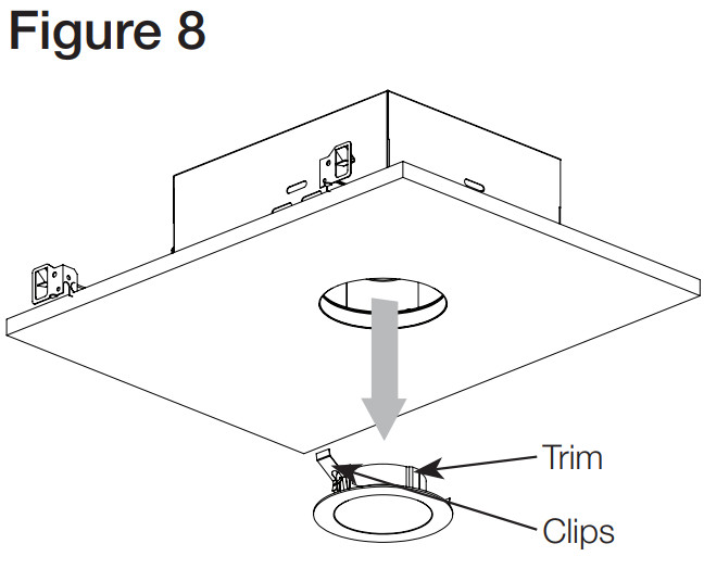
- Remove trima. For Trimmed fixtures: Pull-on flange of trim until the trim is free(Figure 8).b. For Trimless fixtures: Press glass upwards and pull down on the aperture of the trim until it is released from the mud ring.
- Field replace reflector (Figure 9).a. Remove the trim. Refer to step 1 above.b. Hold reflector by edges. Twist counter-clockwise to unlock from the light module.c. Carefully remove the reflector.Note: Do NOT touch the reflective surface of the reflector.d. Install a new reflector. Twist clockwise to lock into the light module.
- Field replace light module (Figure 10).a. Match LED module number on module grab plate (Figure 4) to housing label, located inside the fixture housing.b. Remove the trim. Refer to step 1 above.c. Grab the module at the support and pull the light module out of the module support bracket.d. Disconnect module from the connector.e. Connect the new module to the connector.f. Secure new module into module support bracket. Make sure all wiring is clear from the support bracket, light module, and reflector.
- Field replace LED controller (driver) (Figure 11).Note: Refer to LED controller (driver) replacement guide providedwith the LED controller (driver).a. Follow steps 1, 2, and 3 to remove the trim, reflector, and light module.b. For Downlight fixtures or Adjustable fixtures with the tilt-lock screw installed, remove the support bracket locking screw and rotate the bracket away from the driver to access the controller (driver) compartment. Light modulec. Remove the wing nut(s) on the LED controller (driver) support bracket.d. Remove the LED controller (driver) from the support bracket and pull it out of the aperture (Figure 11). Disconnect the wires from the existing LED controller (driver).e. Transfer the wing nut(s) to the studs on the new LED controller (driver) and connect the wires to the new LED controller (driver).f. Insert the new LED controller (driver) into the aperture and install it into the support bracket.g. Install the wing nut(s) on the support bracket.
- Restore Power
 b. For Trimless fixtures: Press glass upwards and pull down on the aperture of the trim until it is released from the mud ring.
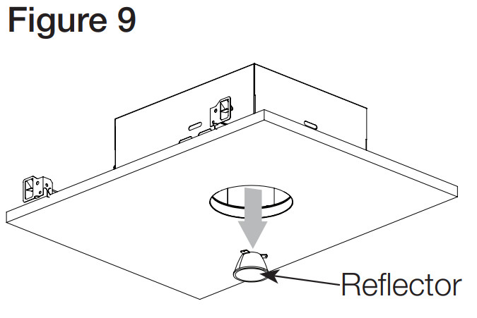 a. Remove the trim. Refer to step 1 above.b. Hold reflector by edges. Twist counter-clockwise to unlock from the light module.c. Carefully remove the reflector.Note: Do NOT touch the reflective surface of the reflector.d. Install a new reflector. Twist clockwise to lock into the light module.
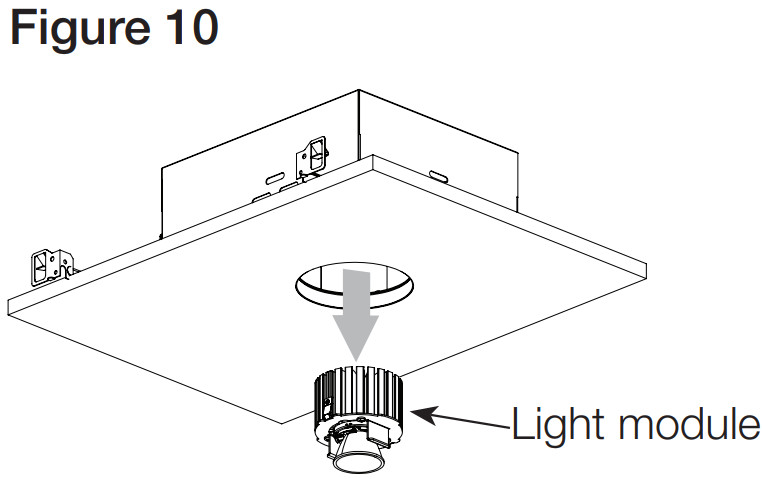 a. Match LED module number on module grab plate (Figure 4) to housing label, located inside the fixture housing.b. Remove the trim. Refer to step 1 above.c. Grab the module at the support and pull the light module out of the module support bracket.d. Disconnect module from the connector.e. Connect the new module to the connector.f. Secure new module into module support bracket. Make sure all wiring is clear from the support bracket, light module, and reflector.
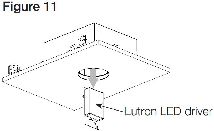 e. Transfer the wing nut(s) to the studs on the new LED controller (driver) and connect the wires to the new LED controller (driver).f. Insert the new LED controller (driver) into the aperture and install it into the support bracket.g. Install the wing nut(s) on the support bracket.
Troubleshooting
| Symptoms | Solution(s) |
| The light is flickering,flashing, dropping out, or does not turn on. | •Check all fixture wires and connections to ensure that they are properly connected.•Verify that controls and controllers (drivers) are connected properly.•Verify that a compatible control is being used to control the controller (driver). For a list of compatible controls and control ratings, visit www.lutron.com/finire•Ensure that 120/277 V—- power is present and properly connected to the LED controller (driver). Note: Fl model (2-wire) is 120 V— only.•Adjust low-end trim on the control.•Verify that ambient temperature is within the specified range.•Non-IC fixtures are intended for free-air applications. Do not confine Non-IC fixtures with insulation or building materials. |
| LED exhibits a flash or steppy dimming on first use. | •Drivers will “learn” the LED load on the first startup. This is a one-time event for a particular controller (driver)/LED combination. Running the load at full output for 20 seconds will complete “learning.” |
| LED does not dim. | •Verify that the controller (driver) wiring is wired properly. |
| The Trim does not fit. | •Verify that an adjustable trim is being used with an adjustable housing. If using a downlight trim with an Adjustable fixture, verify that the tilt is 20° or less.•Trimless fixtures: Ensure that the inside of mud ring is free of excess plaster.•Trimmed fixtures: Ensure ceiling material thickness matches trim specification. Thick ceiling trim brackets are required for ceiling material greater than 0.625 in (16 mm). |
- If a Lutron system is installed on-site and assistance is needed with programming or performance issues, please contact Lutron Lighting technical support at 1.844.LUTRON1 (1.844.588.7661) or [email protected]
FCC StatementThis device complies with part 15 of the FCC Rules. Operation is subject to the following two conditions:
- This device may not cause interference, and
- This device must accept any interference, including interference that may cause undesired operation. Modifications not expressly approved by Lutron Electronics
Co., Inc. could void the user’s authority to operate this equipment.NOTE: This equipment has been tested and found to comply with the limits for a Class B digital device, pursuant to part 15 of the FCC Rules. These limits are designed to provide reasonable protection against harmful interference in a residential installation. This equipment generates, uses and can radiate radio frequency energy and, if not installed and used in accordance with the instructions, may cause harmful interference to radio communications. However, there is no guarantee that interference will not occur in a particular installation. If this equipment does cause harmful interference to radio or television reception, which can be determined by turning the equipment off and on, the user is encouraged to try to correct the interference by one or more of the following measures:
- Reorient or relocate the receiving antenna
- Increase the separation between the equipment and receiver
- Connect the equipment into an outlet on a circuit different from that to which the receiver is connected
- Consult the dealer or an experienced radio/TV technician for helpCAN ICES-005 (B) / NMB-005 (B)
CIRCUIT DIAGRAMS
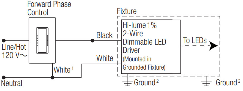
F1: 2-Wire Forward Phase Control with Neutral (120 V~ ONLY )
HO: HomeWorks Digital Control (120 V~)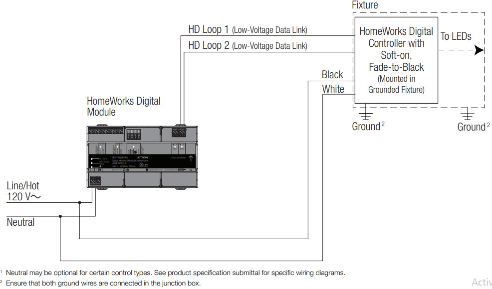
- For custom options please contact Lighting technical Support at [email protected] or1.844.LUTRON1 (1.844.588.7661)
- For a list of compatible controls and control ratings, visit www.lutron.com/finire or contact the LEDControl Center of Excellence at 1.844.LUTRON1 (1.844.588.7661)
Drywall/Plaster Cut-out Template: Round
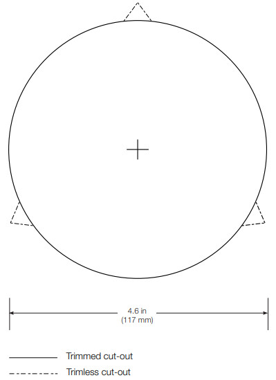
Note: Template is not for use with timeless wood/stone option. Please see Application Note #564 (P/N 048564) at www.lutron.com for details.
Drywall/Plaster Cut-out Template: Square
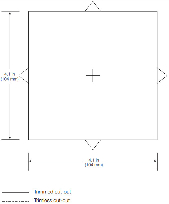
Note: Template is not for use with triple Note: Template is not for use with timeless wood/stone option. Please see Application Note #564 (P/N 048564) at www.lutron.com for details.

The Lutron logo, Lutron, HomeWorks, Hi-lume, IVALO,IVALO Lighting, Lutron Ivalo Collection and Soft-on, Fade-to-Blacks are trademarks or registered trademarks of Lutron ElectronicsCo., Inc. in the US and/or other countries.All other product names, logos, and brands are the property of their respective owners.©2012-2021 Lutron Electronics Co., Inc.
Lutron Electronics Co., Inc.7200 Suter Road, Coopersburg, PA 18036Telephone 610.282.3800www.lutron.comFor limited 5-year warranty details, go to www.lutron.comSpecification subject to change without notice
References
[xyz-ips snippet=”download-snippet”]